Table of Contents
Advertisement
Advertisement
Table of Contents

Related Manuals for GE VMIVME-7807 Series


Summary of Contents for GE VMIVME-7807 Series
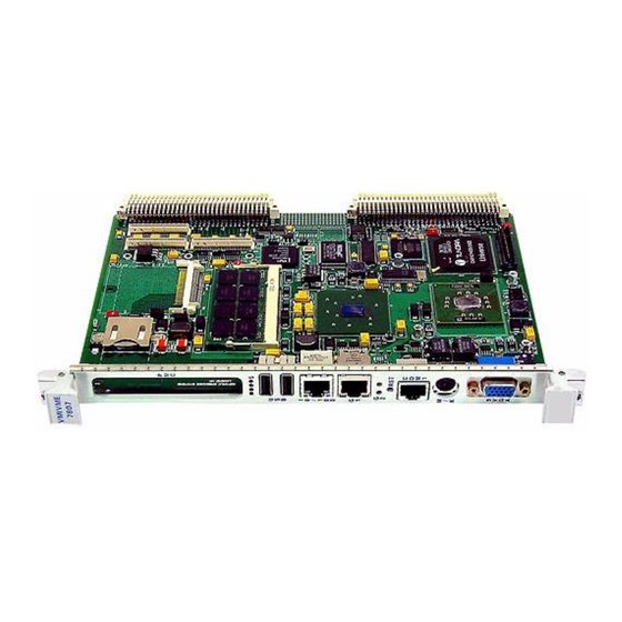
- Page 1 Intelligent Platforms Hardware Reference VMIVME-7807*/VME-7807RC* ® ® Intel Pentium M-Based VME SBC THE VME-7807RC IS DESIGNED TO MEET THE EUROPEAN UNION (EU) RESTRICTION OF HAZARDOUS SUBSTANCE (ROHS) DIRECTIVE (2002/95/EC) CURRENT REVISION. Publication No: 500-007807-000 Rev. P...
- Page 2 July 26, 2010 Waste Electrical and Electronic Equipment (WEEE) Returns GE is registered with an approved Producer Compliance Scheme (PCS) and, subject to suitable contractual arrangements being in place, will ensure WEEE is processed in accordance with the requirements of the WEEE Directive.
-
Page 3: Table Of Contents
Table of Contents List of Figures ................. 5 List of Tables . - Page 4 3.4 Watchdog Timer................39 3.4.1 WDT Control Status Register (WCSR) .
-
Page 5: List Of Figures
List of Figures Figure 1-1 VMIVME-7807/VME-7807RC PMC Site and Switch Locations ........16 Figure 1-2 VMIVME-7807/VME-7807RC Connector Locations . -
Page 6: List Of Tables
List of Tables Table 1-1 VMIVME-7807/VME-7807RC Connectors and Switches ......... .18 Table 1-2 Battery Enable (User Configurable) - Header (E3) . - Page 7 Table B-5 AMI BIOS Boot Menu ................63 Table B-6 AMI BIOS Security Menu .
-
Page 8: Overview
Overview ® GE’s VMIVME‐7807*/VME‐7807RC* are full featured Pentium M‐based, single board computers (SBCs) in a single‐slot, passively cooled, VME Eurocard form ® factor. These products utilize the advanced technology of Intel ’s 855GME chipset. The VMIVME‐7807/VME‐7807RC provide features typically found on desktop systems such as: • 1.0 GByte DDR SDRAM using one SODIMM and an optional 512 MByte of solder‐in memory for a maximum of 1.5 GByte • Built‐in SVGA support (front panel connection) • Digital video controller (rear I/O) DVI‐D with dual head display capabilities • 10/100 Mbit Ethernet controller (front panel connection) • Dual Gigabit Ethernet support (front panel or rear I/O) • Optional P0 with VITA 31.1 interface • Serial ATA (SATA) support (rear I/O) • Serial port COM1 (front panel connection) • Ultra IDE drive support (rear I/O) • Real‐Time clock/calendar • Front panel reset switch • Miniature speaker • Keyboard/Mouse port (front panel connection) The 855GME chipset allows the VMIVME‐7807/VME‐7807RC to provide enhanced features such as integrated video and Ultra ATA/100 IDE support. The ... - Page 9 Additionally, the VMIVME‐7807/VME‐7807RC offer one PMC expansion site (PCI‐X, 66 MHz) with front panel access. The VMIVME‐7807/VME‐7807RC are ® capable of executing many of today’s operating systems such as VxWorks , ® Solaris™ or QNX . The embedded features of the VMIVME‐7807/VME‐7807RC are described in Chapter 3 “Embedded PC/RTOS Features” of this manual. The VMIVME‐7807/VME‐7807RC are suitable for use in applications ranging from telecommunications, simulation, instrumentation, industrial control, process control and monitoring, factory automation, automated test systems, data acquisition systems and anywhere that the highest performance processing power in a single VME slot is desired. Intel 855GME Chipset The VMIVME‐7807/VME‐7807RC incorporate the latest Intel chipset technology, the 855GME. This chipset utilizes Advanced Hub Architecture (AHA). The AHA allows for increased system performance by separating many high‐bandwidth I/O accesses from PCI accesses, relieving bottlenecks on the PCI bus. Furthermore, the 855GME chipset brings new levels of integration to motherboard chipsets and provides additional features such as Integrated LVDS and Serial ATA. Overview 9...
- Page 10 Figure 1 VMIVME-7807/VME-7807RC Block Diagram VMIVME-7807/ Intel Pentium M up to 1.8 GHz VME-7807RC Processor NVRAM CompactFlash (Optional) 512 MByte Processor Soldered in System bus SDRAM Memory PC2100 (Optional) Up to 1.0 GByte FPGA Timer, Watchdog, NVRAM Intel 855GME System Memory bus Control Graphics and Memory Controller Hub...
- Page 11 Organization This manual is composed of the following chapters and appendices: Chapter 1 ‐ Installation and Setup describes unpacking, inspection, hardware jumper settings, connector definitions, installation, system setup and operation of the VMIVME‐7807/VME‐7807RC . Chapter 2 ‐ Standard Features describes the unit design in terms of the standard PC memory and I/O maps, along with the standard interrupt architecture. Chapter 3 ‐ Embedded PC/RTOS Features describes the unit features that are beyond standard functions. Maintenance provides information relative to the care and maintenance of the unit. Compliance provides applicable information regarding regulatory compliance. Appendix A ‐ Connector Pinouts illustrates and defines the connectors included in the unit’s I/O ports. Appendix B ‐ AMI BIOS Setup Utility describes the menus and options associated with the AMI (system) BIOS. Appendix C ‐ Intel Boot Agent describes the menus and options associated with the LAN Boot BIOS. Appendix D ‐ System Driver Software describes the steps required to load system drivers. Overview 11...
- Page 12 References Intel Pentium M Processor Datasheet June 2003, Order Number 252612‐002 Intel 855GME Chipset Graphics and Memory Controller Hub (GMCH) March 2003, Order Number 252615‐001 Intel 6300ESB I/O Controller Hub February 2004, Order Number 300641‐001 PCI Local Bus Specification, Rev. 2.2 PCI Special Interest Group P.O. Box 14070 Portland, OR 97214 (800) 433‐5177 (U.S.) (503) 797‐4207 (International) (503) 234‐6762 (FAX) LPC47M107 100‐Pin Enhanced Super I/O with LPC Interface for Consumer Applications Standard Microsystems Corp. 80 Askay Dr. Hauppauge, NY 11788‐8847 www.smsc.com CMC Specification, P1386/Draft 2.0 from: IEEE Standards Department Copyrights and Permissions 445 Hoes Lanes, P.O. Box 1331 Piscataway, NJ 08855‐1331 PMC Specification, P1386.1/Draft 2.0 from: IEEE Standards Department Copyrights and Permissions 445 Hoes Lanes, P.O. Box 1331 Piscataway, NJ 08855‐1331, USA The following is useful information related to the operation of the I C controllers: The I C Specification version 2.0 Philips Semiconductor 811 East Arques Ave. Sunnyvale, CA 94088‐3409 (800) 234‐7381 www.semiconductors.philips.com C/SMBus‐Compatible Remote/Local Temperature Sensors with Overtemperature Alarms Maxim Integrated Products, Inc.
- Page 13 Safety Summary The following general safety precautions must be observed during all phases of the operation, service and repair of this product. Failure to comply with these precautions or with specific warnings elsewhere in this manual violates safety standards of design, manufacture and intended use of this product. GE assumes no liability for the customerʹs failure to comply with these requirements. Ground the To minimize shock hazard, the chassis and system cabinet must be connected to System an electrical ground. A three‐conductor AC power cable should be used. The power cable must either be plugged into an approved three‐contact electrical outlet or used with a three‐contact to two‐contact adapter with the grounding wire (green) firmly connected to an electrical ground (safety ground) at the power outlet. Do Not Operate in Do not operate the system in the presence of flammable gases or fumes. Operation an Explosive of any electrical system in such an environment constitutes a definite safety Atmosphere hazard. Keep Away from Operating personnel must not remove product covers. Component replacement Live Circuits and internal adjustments must be made by qualified maintenance personnel. Do not replace components with power cable connected. Under certain conditions, dangerous voltages may exist even with the power cable removed. To avoid injuries, always disconnect power and discharge circuits before touching them. Do Not Service or Do not attempt internal service or adjustment unless another person capable of ...
- Page 14 Warnings, Cautions WARNING and Notes WARNING denotes a hazard. It calls attention to a procedure, practice, or condition, which, if not correctly performed or adhered to, could result in injury or death to personnel. CAUTION CAUTION denotes a hazard. It calls attention to an operating procedure, practice, or condition, which, if not correctly performed or adhered to, could result in damage to or destruction of part or all of the system.
-
Page 15: Installation And Setup
CAUTION Some of the components assembled on GE products may be sensitive to electrostatic discharge and damage may occur on boards that are subjected to a high energy electrostatic field. When the board is placed on a bench for configuring, etc., it is suggested that conductive material be inserted under the board to provide a conductive shunt . -
Page 16: Figure 1-1 Vmivme-7807/Vme-7807Rc Pmc Site And Switch Locations
Figure 1-1 VMIVME-7807/VME-7807RC PMC Site and Switch Locations E3 Battery Enable Jumper installed, battery enable. Jumper removed, battery disabled. S2 CMOS Clear/BIOS Boot Mode S8 NOT USED Position 1, Off = Default (Normal Operation) Battery Position 1, On = Clear CMOS Enable Position 2, Off = Default (Boot Halt with Post... -
Page 17: Figure 1-2 Vmivme-7807/Vme-7807Rc Connector Locations
Figure 1-2 VMIVME-7807/VME-7807RC Connector Locations CompactFlash SODIMM Optional Optional 10/100 P0 P0 Optional Optional COM1 J9 J9 SVGA Installation and Setup 17... -
Page 18: Table 1-1 Vmivme-7807/Vme-7807Rc Connectors And Switches
ITP connector (on the solder side of the board) 10/100 Mbit RJ45 connector Gigabit Ethernet connector (optional) J11, J12 and J13 PMC Site connectors Serial port connector (COM1) SVGA connector GE PCI expansion connector (PMC237CM1/V) Battery Header Function CMOS header Switches Function... -
Page 19: To Clear The Cmos Password
NOTE The BIOS has the capability of password protecting casual access to the unit’s CMOS setup screens. The CMOS Clear jumper allows the user to clear the password in the case of a forgotten password. Table 1-4 Password Clear/BIOS Boot Mode (User Configurable) - Switch (S2) Position State Function... -
Page 20: Installation
1.3 Installation The VMIVME‐7807/VME‐7807RC conform to the VME physical specification for a 6U board. The VMIVME‐7807/VME‐7807RC can be used for the system controller or as a peripheral board. They can be plugged directly into any standard chassis accepting either type of board. The following steps describe the GE‐recommended method for installation and powerup of the VMIVME‐7807/VME‐7807RC: 1. If a PMC module is to be used, connect it to the VMIVME‐7807/VME‐7807RC prior to board installation (as shown in Figure 1‐3 on page 21). Refer to the Product Manual for the PMC module for configuration and setup. NOTE Air flow requirements as measured at the output side of the heatsink is to be greater than 450 LFM. 2. Insert the VMIVME‐7807/VME‐7807RC into a VME chassis system controller or peripheral slot. While ensuring that the board is properly aligned and ori‐ ented in the supporting board guides, slide the board smoothly forward against the mating connector. Use the ejector handles to firmly seat the board. 3. All needed peripherals can be accessed from the front panel or the rear I/O ... -
Page 21: Figure 1-3 Installing The Pmc Card On The Vmivme-7807/Vme-7807Rc
Figure 1-3 Installing the PMC Card on the VMIVME-7807/VME-7807RC Installation and Setup 21... -
Page 22: Figure 1-4 Backside Mounting For The Pmc Card
Figure 1-4 Backside Mounting for the PMC Card 22 VMIVME-7807/VME-7807RC Hardware Reference Manual... -
Page 23: Front/Rear Panel Connectors
• USB Dual USB 2.0 Ports • 10/100 10/100 Mbit Ethernet connector • G1 10/100/1000 Mbit Ethernet connector 1 (or LEDs) port 1 • G2 10/100/1000 Mbit Ethernet LEDs port 2 • M/K Mouse/keyboard connector • COM1 Serial Port • RST Manual reset switch • S Status LEDs • SVGA Analog Video connector The VMIVME‐7807/VME‐7807RC provide rear I/O support for the following: digital video, Serial ATA, COM2, 3 and 4, IDE drive and two USB ports. These signals are accessed by the use of an RTM such as the VMIACC‐0586/ ACC‐0586RC and the VMIACC‐0590/ACC‐0590RC, which terminates into industry standard connectors. The front panel connectors, including connector pinouts and orientation, for the VMIVME‐7807/VME‐7807RC are defined in “Appendix A: Connector Pinouts”. Rear panel connections are defined in the appropriate RTM Installation Guide. Contact Sales for compatible RTMs offered by GE. Installation and Setup 23... -
Page 24: Figure 1-5 Vmivme-7807/Vme-7807Rc Front Panels
Figure 1-5 VMIVME-7807/VME-7807RC Front Panels VME Standard VME Standard 1101.10 1101.10 Front Panel Front Panel Front Panel Front Panel without with with without Gigabit Ethernet Gigabit Ethernet Gigabit Ethernet Gigabit Ethernet Front Panel Access Front Panel Access Front Panel Access Front Panel Access VMIVME VMIVME... -
Page 25: Front Panel Layout
1.5 Front Panel Layout Figure 1-6 Front Panel Layout Status LEDs (from left to right) Sysfail VME failure ‐ Lights during VME SYSFAIL condition, (Red LED). Power ‐ Indicates when VMIVME power is applied to the 7807 board, (Green LED). Activity Indicator ‐ Flashes when IDE activity is occurring, (Yellow LED). Boot Done Booting ‐ Indicates BIOS Boot is in progress. When LED is Off, CPU has finished POST and is ready (Red LED). RST Switch Reset Allows the system to be USBs reset from the front panel. Activity 10/100 Ethernet LEDs 10/100 Link Activity Indicates the Ethernet is Gigabit Activity Ethernet active, (Green LED). -
Page 26: Standard Features
2 • Standard Features The VMIVME‐7807/VME‐7807RC are Pentium M processor‐based single board computers compatible with modern industry standard desktop systems. The VMIVME‐7807/VME‐7807RC therefore retain industry standard memory and I/O maps along with a standard interrupt architecture. The integrated peripherals described in this section (such as serial ports, USB ports, IDE drives, floppy drives, video controller and Ethernet controller) are all memory mapped the same as similarly equipped desktop systems, ensuring compatibility with modern operating systems. The following sections describe the standard features of the VMIVME‐7807/VME‐7807RC. 2.1 BGA CPU The VMIVME‐7807/VME‐7807RC are factory populated with a Pentium M processor. To change the memory size or CompactFlash size contact Customer Care to receive a Return Material Authorization (RMA). 2.2 Physical Memory The VMIVME‐7807/VME‐7807RC provide DDR Synchronous DRAM (SDRAM) as onboard system memory. Memory can be accessed as bytes, words or longwords. The VMIVME‐7807/VME‐7807RC accept one 200‐pin DDR SDRAM SODIMM along with the optional solder‐in 512 MByte onboard memory, for a maximum capacity of 1.5 GByte. The onboard DRAM is accessible to the VME through the PCI‐to‐PCI bridge and is addressable by the local processor. NOTE Memory capacity may change due to part availability. 26 VMIVME-7807/VME-7807RC Hardware Reference Manual... -
Page 27: Pci Device Interrupt Map
PCI_AD[21] PCI_IRQA# 8086H 1079H* Gigabit Ethernet #2 PCI_GNT[1]# PCI1_REQ[0]# PCI_AD[21] PCI_IRQB# 8086H 1079H 82551 PCI_GNT[2]# PCI0_REQ[2]# PCI_AD[28] PCI_IRQF# 8086H GE Conn PCI_GNT[3]# PCI0_REQ[3]# PCI_AD[20] PCI_IRQ[A:D]# *The Device ID for the Intel 82546EB is 1010H. The Device ID for the Intel 82546GB is 1079H. 2.4 Integrated Peripherals The VMIVME‐7807/VME‐7807RC incorporate an SMSC Super I/O (SIO) chip. The SIO provides the VMIVME‐7807/VME‐7807RC with two 16550 UART‐compatible serial ports, keyboard and mouse ports. The keyboard and mouse ports are available via the front panel using a standard PS/2 type connector. COM1 is accessed via the front panel. COM2 is routed to the VME P2 connector. COM ports 3 and 4 are also provided by the 6300ESB I/O Controller Hub and are routed to the VME P2 connector. The parallel IDE interface is provided by the Intel 6300ESB I/O Controller Hub. The IDE interface supports two channels: primary and secondary. The secondary channel is routed onboard to the optional CompactFlash socket. The primary ... -
Page 28: Ethernet Controller
2.5 Ethernet Controller The network capability is provided by the Intel 82546EB for the VMIVME‐7807 or the Intel 82546GB for the VME‐7807RC Ethernet Controller for Gigabit Ethernet and the Intel 82551 10/100 Mbit Ethernet. These Ethernet controllers are PCI bus based and are software configurable. The VMIVME‐7807/VME‐7807RC support 10Base‐T, 100Base‐TX and 1000Base‐T Ethernet. 10Base-T A network based on the 10Base‐T standard uses unshielded twisted‐pair cables, providing an economical solution to networking by allowing the use of existing telephone wiring and connectors. The RJ45 connector is used with the 10Base‐T standard. 10Base‐T has a maximum length of 100 meters. 100Base-TX The VMIVME‐7807/VME‐7807RC also support the 100Base‐TX Ethernet. A network based on a 100Base‐TX standard uses unshielded twisted‐pair cables and an RJ45 connector. 100Base‐TX has a maximum length of 100 meters. 1000Base-T The VMIVME‐7807/VME‐7807RC support 1000Base‐T Ethernet using the Intel 82546EB for the VMIVME‐7807 or the Intel 82546GB for the VME‐7807RC dual Ethernet controller. The interface uses shielded cables with four pairs of conductors, along with an RJ45 connector on the front panel or routed to the VME P2 connector. The Gigabit Ethernet is also available with the optional VITA 31.1 routed out of the optional P0 connector. NOTE Ethernet activity is noted on the front panel LEDs by a blinking yellow LED. The yellow LED will be on continuously when the Ethernet port is linked but with no activity. -
Page 29: Digital Visual Interface (Dvi)
Table 2-3 Supported Graphics Video Resolutions for Windows XP (Analog) Screen Resolution Maximum Colors Maximum Refresh Rates (Hz) 640 x 480 High and True are supported at all resolutions. 800 x 600 1024 x 768 1080 x 1280 1600 x 1200 Not all SVGA monitors support resolutions and refresh rates beyond 640 x 480 at ... -
Page 30: Dvi Connectors
2.6.2 DVI Connectors The DVI connector has twenty‐four pins that can accommodate up to two TMDS links and the VESA DDC and EDID services. The DVI specification defines two types of connectors (see Figure 1): • DVI‐Digital (DVI‐D) supports digital displays only (used on the VMIVME‐7807/VME‐7807RC) • DVI‐Integrated (DVI‐I) supports digital displays and is backward compati‐ ble with analog displays (not supported) The VMIVME‐7807/VME‐7807RC use the DVI‐I connector with a single TMDS link. The DVI‐I interface accommodates a 12‐ or 24‐pin DVI plug connector or a new type of analog plug connector that uses four additional pins, plus a ground plane plug to maintain a constant impedance for the analog RGB signals. 2.6.3 Dual Head Video The VMIVME‐7807/VME‐7807RC are capable of driving two monitors at the same time using the Intel 855GME GMCH. The graphics controller allows the use of one digital monitor connected to the VMIACC‐0590/ACC‐0590RC or VMIACC‐0586/ ACC‐0586RC RTMs, routed out the rear I/O P2 connector. The second is a standard SVGA monitor connected to the front panel of the VMIVME‐7807/VME‐7807RC, using a standard DB15 connector. Dual Head Setup 1. Boot Windows 2000. Procedure: 2. In the windows desktop right click. 3. When the menu appears, scroll down to the ‘Graphics Options’ and then click on ‘Graphics Properties’. The Intel 82852/82855GM/GME graphics con‐ troller properties menu will appear. From this menu you can choose the dis‐ play mode of choice. The monitors can be displayed in several modes: • ... -
Page 31: Hot Keys
2.6.4 Hot Keys The Intel 855GME Graphic and Memory Controller allows the use of hot keys to set up the monitors. See Table 2‐4 for hot key combinations. Table 2-4 Hot Key Combinations Action Hot Key Combination Enable Monitor <CTRL><ALT><F1> Enable Notebook <CTRL><ALT><F3> Enable Digital Display <CTRL><ALT><F4> Invoke Graphics Properties <CTRL><ALT><F12> Rotate Normal <CTRL><ALT><UP> Rotate 90 Degrees <CTRL><ALT><LEFT> Rotate 180 Degrees <CTRL><ALT><DOWN> Rotate 270 Degrees <CTRL><ALT><RIGHT>... -
Page 32: Embedded Pc/Rtos Features
3 • Embedded PC/RTOS Features GE’s VMIVME‐7807/VME‐7807RC feature additional capabilities beyond those of a typical desktop computer system. The units provide four software‐controlled, general‐purpose timers along with a programmable Watchdog Timer for synchronizing and controlling multiple events in embedded applications. The VMIVME‐7807/VME‐7807RC also provide a bootable CompactFlash system and 32 KByte of non‐volatile RAM. Also, the VMIVME‐7807/VME‐7807RC support an embedded intelligent VME bridge to allow compatibility with the most demanding VME applications. These features make the unit ideal for embedded applications, particularly where standard hard drives and floppy disk drives cannot be used. 3.1 VME Bridge In addition to their desktop functions, the VMIVME‐7807/VME‐7807RC have the following VME features: 3.1.1 Features • Complete six‐line Address Modifier (AM‐Code) programmability • VME data interface with separate hardware byte/word swapping for master and slave accesses • Support for VME64 multiplexed MBLT 64‐bit VME block transfers • User‐configured interrupter • User‐configured interrupt handler • System Controller mode with programmable VME arbiter (PRI, SGL and RRS modes are supported) • VME BERR bus error timer (software programmable) • Slave access from the VME to local RAM and mailbox registers • ... -
Page 33: I2C/Smbus Temperature Sensor
PCI Base Address 2 for Memory Mapped Watchdog and other timers (BAR2) Reserved Reserved Reserved Reserved Subsystem ID 7807 Subsystem Vendor ID 114A Reserved Reserved Reserved Max_Lat Min_gnt Interrupt Pin Interrupt Line The “Device ID” field indicates that the device is for VME products (00) and indicates the supported embedded feature set. ® The “Vendor ID” and “Subsystem Vendor ID” fields indicate GE’s PICMG assigned Vendor ID (114A). The “Subsystem ID” field indicates the model number of the product (7807). Embedded PC/RTOS Features 33... -
Page 34: Timers
3.3 Timers The VMIVME‐7807/VME‐7807RC provide four user‐programmable timers (two 16‐bit and two 32‐bit) which are completely dedicated to user applications and are not required for any standard system function. Each timer is clocked by independent generators with selectable rates of 2 MHz, 1 MHz, 500 kHz and 250 kHz. Each timer may be independently enabled and each is capable of generating a system interrupt on timeout. Events can be timed by either polling the timers or enabling the interrupt capability of the timer. A status register allows for application software to determine which timer is the cause of any interrupt. 3.3.1 Timer Control Status Register 1 (TCSR1) The timers are controlled and monitored via the Timer Control Status Register 1 (TCSR1) located at offset 0x00 from the address in BAR2. The mapping of the bits in this register are shown in Table 3‐2. Table 3-2 TCSR1 Bit Mapping Field Bits Read or Write Timer 1 Caused IRQ TCSR1[0] Timer 1 Enable TCSR1[1] Timer 1 IRQ Enable TCSR1[2] Timer 1 Clock Select... -
Page 35: Timer Control Status Register 2 (Tcsr2)
Each timer can be independently enabled by writing a “1” to the appropriate “Timer x Enable” field. Similarly, the generation of interrupts by each timer can be independently enabled by writing a “1” to the appropriate “Timer x IRQ Enable” field. If an interrupt is generated by a timer, the source of the interrupt may be determined by reading the “Timer x Caused IRQ” fields. If the field is set to “1”, then the respective timer caused the interrupt. Note that multiple timers can cause a single interrupt. Therefore, the status of all timers must be read to ensure that all interrupt sources are recognized. A particular timer interrupt can be cleared by writing a “0” to the appropriate “Timer x Caused IRQ” field. Alternately, a write to the appropriate Timer x IRQ Clear (TxIC) register will also clear the interrupt. When clearing the interrupt using the “Timer x Caused IRQ” fields, note that it is very important to ensure that a proper bit mask is used so that other register settings are not affected. The preferred method for clearing interrupts is to use the “Timer x IRQ Clear” registers described on page 37. 3.3.2 Timer Control Status Register 2 (TCSR2) The timers are also controlled by bits in the Timer Control Status Register 2 (TCSR2) located at offset 0x04 from the address in BAR2. The mapping of the bits in this register is shown in Table 3‐4. Table 3-4 TCSR2 Bit Mapping Field Bits Read or Write Read Latch Select TCSR2[0] Reserved All Other Bits All of these bits default to “0”... -
Page 36: Timer 3 Load Count Register (Tmrlcr3)
Table 3-5 TMRLCR12 Bit Mapping Field Bits Read or Write Timer 2 Load Count TMRLCR12[31..16] Timer 1 Load Count TMRLCR12[15..0] When either of these fields are written (either by a single 32‐bit write or separate 16‐bit writes), the respective timer is loaded with the written value on the next rising edge of the timer clock, regardless of whether the timer is enabled or disabled. The value stored in this register is also automatically reloaded on terminal count (or timeout) of the timer. 3.3.4 Timer 3 Load Count Register (TMRLCR3) Timer 3 is 32‐bits wide and obtains its load count from the Timer 3 Load Count Register (TMRLCR3), located at offset 0x14 from the address in BAR2. The mapping of bits in this register is shown in Table 3‐6. Table 3-6 TMRLCR3 Bit Mapping Field Bits Read or Write... -
Page 37: Timer 3 Current Count Register (Tmrccr3)
Table 3-8 TMRCCR12 Bit Mapping Field Bits Read or Write Timer 2 Count TMRCCR12[31..16] Read Only Timer 1 Count TMRCCR12[15..0] Read Only When either field is read, the current count value is latched and returned. There are two modes that determine how the count is latched depending on the setting of the “Read Latch Select” bit in the WDT Control Status Register (CSR2). See the CSR2 register description for more information on these two modes. 3.3.7 Timer 3 Current Count Register (TMRCCR3) The current count of Timer 3 may be read via the Timer 3 Current Count Register (TMRCCR3), located at offset 0x24 from the address in BAR2. The mapping of bits in this register is shown in Table 3‐9. Table 3-9 TMRCCR3 Bit Mapping Field Bits Read or Write... -
Page 38: Timer 2 Irq Clear (T2Ic)
3.3.10 Timer 2 IRQ Clear (T2IC) The Timer 2 IRQ Clear (T2IC) register is used to clear an interrupt caused by Timer 2. Writing to this register, located at offset 0x34 from the address in BAR2, causes the interrupt from Timer 2 to be cleared. This can also be done by writing a “0” to the appropriate “Timer x Caused IRQ” field of the timer Control Status Register (CSR1). This register is write only and the data written is irrelevant. 3.3.11 Timer 3 IRQ Clear (T3IC) The Timer 3 IRQ Clear (T3IC) register is used to clear an interrupt caused by Timer 3. Writing to this register, located at offset 0x38 from the address in BAR2, causes the interrupt from Timer 3 to be cleared. This can also be done by writing a “0” to the appropriate “Timer x Caused IRQ” field of the timer Control Status Register (CSR1). This register is write only and the data written is irrelevant. 3.3.12 Timer 4 IRQ Clear (T4IC) The Timer 4 IRQ Clear (T4IC) register is used to clear an interrupt caused by Timer 4. Writing to this register, located at offset 0x3C from the address in BAR2, causes the interrupt from Timer 4 to be cleared. This can also be done by writing a “0” to the appropriate “Timer x Caused IRQ” field of the timer Control Status Register (CSR1). This register is write only and the data written is irrelevant. 38 VMIVME-7807/VME-7807RC Hardware Reference Manual... -
Page 39: Watchdog Timer
3.4 Watchdog Timer The VMIVME‐7807/VME‐7807RC provide a programmable Watchdog Timer (WDT) which can be used to reset the system if software integrity fails. 3.4.1 WDT Control Status Register (WCSR) The WDT is controlled and monitored by the WDT Control Status Register (WCSR) which is located at offset 0x08 from the address in BAR2. The mapping of the bits in this register is shown in Table 3‐11. Table 3-11 WCSR Bit Mapping Field Bits Read or Write SERR/RST Select WCSR[16] WDT Timeout Select WCSR[10..8] WDT Enable WCSR[0] All of these bits default to “0” after system reset. All other bits are reserved. The “WDT Timeout Select” field is used to select the timeout value of the WDT as ... -
Page 40: Wdt Keepalive Register (Wkpa)
3.4.2 WDT Keepalive Register (WKPA) When enabled, the Watchdog Timer is prevented from resetting the system by writing to the WDT Keepalive Register (WKPA) located at offset 0x0C from the address in BAR2 within the selected timeout period. The data written to this location is irrelevant. 3.5 NVRAM The VMIVME‐7807/VME‐7807RC provide 32 KByte of non‐volatile RAM. This memory is mapped in 32 Kbytes of address space starting at the address in BAR1. This memory is available at any time and supports byte, short word and long word accesses from the PCI bus. The contents of this memory are retained when the power to the board is removed. 40 VMIVME-7807/VME-7807RC Hardware Reference Manual... -
Page 41: Vme Control
3.6 VME Control Table 3‐13 shows the register definitions for the VMIVME‐7807/VME‐7807RC (offset from BAR0). Table 3-13 Register Definitions Offset from BAR0 Register and Offset Bit Name Definition VMECOMM MEC_SEL Master Big-Endian Enable bit 1=Big Endian, 0=Little Endian Offset 0x00 SEC_SEL Slave Big-Endian Enable bit 1=Big Endian, 0=Little Endian ABLE Auxiliary BERR Logic Enable bit 1=Aux. -
Page 42: Compactflash
3.7 CompactFlash The VMIVME‐7807/VME‐7807RC feature an optional onboard CompactFlash mass storage system with a capacity of up to 2 GByte. This CompactFlash appears to the user as an intelligent ATA (IDE) disk drive with the same functionality and capabilities as a “rotating media” IDE hard drive. The VMIVME‐7807/VME‐7807RC BIOS include an option to allow the board to boot from the CompactFlash with user‐provided operating system. 3.7.1 Configuration The CompactFlash resides on the VMIVME‐7807/VME‐7807RC as the secondary IDE bus master device (the secondary IDE bus slave device is not assignable). 3.8 Remote Ethernet Booting The VMIVME‐7807/VME‐7807RC are capable of booting from a server using either of the GbE Ethernet ports (front and rear I/O) over a network utilizing an Expansion ROM BIOS that enables processor booting from a network server. The facility supports PXE. The Ethernet must be connected through the GbE front panel (RJ45) connector or rear I/O GbE to boot remotely. This feature allows users to create systems without the worry of disk drive reliability or the extra cost of adding CompactFlash drives. 42 VMIVME-7807/VME-7807RC Hardware Reference Manual... -
Page 43: Maintenance
Maintenance If a GE product malfunctions, please verify the following: 1. Software version resident on the product 2. System configuration 3. Electrical connections 4. Jumper or configuration options 5. Boards are fully inserted into their proper connector location 6. Connector pins are clean and free from contamination 7. No components or adjacent boards were disturbed when inserting or remov‐ ing the board from the chassis 8. Quality of cables and I/O connections If products must be returned, contact GE for a Return Material Authorization (RMA) Number. This RMA Number must be obtained prior to any return from Customer Care. GE Customer Care is available at: 1‐800‐433‐2682 in North America, or +1‐780‐401‐7700 for international calls. Or, visit our website www.ge‐ip.com. Maintenance Prints User level repairs are not recommended. The drawings and diagrams in this manual are for reference purposes only. Maintenance 43... -
Page 44: Compliance
Compliance This chapter provides applicable information regarding regulatory compliance for the VMIVME‐7807/VME‐7807RC. GE’s VMIVME‐7807/VME‐7807RC have been evaluated to and have met the requirements for compliance to the following standards: International Compliance • EN55022:1998/CISPR 22:1997 • EN61000‐4‐2 • EN61000‐4‐3 • EN61000‐4‐4 • EN61000‐4‐5 • EN61000‐4‐6 European Union (CE Mark) • BS EN55024 (1998 w A1:01 & A2: 03) • BS, EN55022 (Class A) United States • FCC Part 15, Subpart B, Section 109, Class A Australia/New Zealand • AS/NZS CISPR 22 (2002) Class A Canada • ICES‐003 Class A Compliance 44... - Page 45 FCC Part 15 This device complies with Part 15 of the FCC Rules. Operation is subject to the following two conditions: (1) this device may not cause harmful interference, and (2) this device must accept any interference received, including interference that may cause undesired operation. FCC Class A NOTE This equipment has been tested and found to comply with the limits for a Class A digital device, pursuant to Part 15 of the FCC Rules. These limits are designed to provide reasonable protection against harmful interference when the equipment is operated in a commercial environment.
-
Page 46: A • Appendix A: Connector Pinouts
A • Appendix A: Connector Pinouts The VMIVME‐7807/VMI‐7807RC VME SBCs have several connectors for their I/O ports. Wherever possible, the VMIVME‐7807/VMI‐7807RC use connectors and pinouts typical for any desktop PC. This ensures maximum compatibility with a variety of systems. Figure A‐1 shows the layout of the connectors on the VMIVME‐7807/ VMI‐7807RC. Connector diagrams in this appendix are generally shown in a natural orientation with the SBC mounted in a VME chassis. Figure A-1 VMIVME-7807/VME-7807RC Connector Layout CompactFlash SODIMM Optional Optional 10/100 Optional Optional COM1 SVGA Appendix A: Connector Pinouts 46... -
Page 47: Vme Connector And Pinout (P1 And P2)
A.1 VME Connector and Pinout (P1 and P2) Figure A‐2 shows the orientation of the P1 and P2 connectors on the VMIVME‐7807/VME‐7807RC. Table A‐1 shows the pinout for the VME P1 and P2 connectors. Figure A-2 VME Connectors (P1/P2) Table A-1 VME Connector Pinout (P1/P2) P1 Row A P1 Row B P1 Row C P1 Row D P1 Row Z P2 Row A P2 Row B P2 Row C P2 Row D... -
Page 48: Vme Connector And Pinout (P0) Optional
A.2 VME Connector and Pinout (P0) Optional The optional P0 pinout is displayed below: Figure A-3 VME Connector (P0) Table A-2 VME Connector and Pinout (P0) Pin No. Row A Row B Row C Row D Row E Row F LPB_BI_DB+ LPB_BI_DB- LPB_BI_DD+ LPB_BI_DD- LPB_BI_DA+ LPB_BI_DA- LPB_BI_DC+ LPB_BI_DC- LPA_BI_DB+... -
Page 49: Pmc Connectors
A.3 PMC Connectors A.3.1 PMC Site Connector and Pinout (J11) The PCI Mezzanine Card (PMC) carries the same signals as the PCI standard; however, the PMC standard uses a completely different form factor. Tables A‐3 through A‐5 show the pinouts for the PMC site connectors. Figure A-4 PMC Site Connector (J11) Table A-3 PMC Site Connector Pinout (J11) PMC Connector (J11) PMC Connector (J11) Left Side Right Side Left Side Right Side Name Name Name... -
Page 50: Pmc Site Connector And Pinout (J12)
A.3.2 PMC Site Connector and Pinout (J12) Figure A-5 PMC Site Connector (J12) Table A-4 PMC Site Connector Pinout (J12) PMC Connector (J12) PMC Connector (J12) Left Side Right Side Left Side Right Side Name Name Name Name VCC_12.0 VCC_3.3 PCI1_TRDY# VCC_3.3 VCC_3.3... -
Page 51: Pmc Site Connector And Pinout (J13)
A.3.3 PMC Site Connector and Pinout (J13) Figure A-6 PMC Site Connector (J13 ) Table A-5 PMC Site Connector Pinout (J13 ) PMC Connector (J13) PMC Connector (J13) Left Side Right Side Left Side Right Side Name Name Name Name AD[48] CBE#7 AD[47]... -
Page 52: Usb Connectors And Pinout (J16 And J17)
A.4 USB Connectors and Pinout (J16 and J17) The USB ports are two industry standard 4‐position shielded connectors. Figure A‐7 shows a representation of the connectors, and Table A‐6 shows the pinout (same for each). Figure A-7 USB Connector (J16 and J17) Table A-6 USB Connector Pinout (J16 and J17) Signal Function USB_VCC USB Power USB- USB Data - USB+ USB Data + USBG USB Ground Appendix A: Connector Pinouts 52... -
Page 53: Gigabit Ethernet Connector And Pinout (J18)
A.5 Gigabit Ethernet Connector and Pinout (J18) The pinout diagram for the Gigabit Ethernet connector and pinout are shown in Figure A‐8 and Table A‐7. Figure A-8 Gigabit Ethernet Connector (J18) Connector Opening Pin #1 Top View Table A-7 Gigabit Ethernet Connector Pinout (J18) Signal Function BI_DA+ Bi-directional pair A + BI_DA- Bi-directional pair A - BI_DB+ Bi-directional pair B + BI_DC+... -
Page 54: Video Graphics Adapter And Pinout (J19)
A.6 Video Graphics Adapter and Pinout (J19) The video port uses a standard high‐density DB15 SVGA connector. Figure A‐9 illustrates the pinout and Table A‐8 gives a description. Figure A-9 SVGA Connector (J19) SVGA Table A-8 SVGA Connector Pinout (J19) Signal VGA_Video1_Red VGA_Video1_Green VGA_Video1_Blue VCC_5.0 VGA_DDC_Data VGA_HSYNC VGA_VSYNC VGA_DDC_CLK N/C indicates No Connection Appendix A: Connector Pinouts 54... -
Page 55: Serial Connector And Pinout (J22)
A.7 Serial Connector and Pinout (J22) COM 1 serial port connector is a standard RJ45 connector as shown in Figure A‐10 and its pinout in Table A‐9. Figure A-10 Serial Connector (J22) Table A-9 Serial Connector Pinout (J22) Direction RS232 Signal Function Data Carrier Detect Request to Send Ground Only Transmit Data Receive Data Ground Clear to Send Data Terminal Ready 55 VMIVME-7807/VME-7807RC Hardware Reference Manual... -
Page 56: Mouse/Keyboard Connector And Pinout (J10)
A.8 Mouse/Keyboard Connector and Pinout (J10) The mouse/keyboard connector is a standard 6‐pin female mini‐DIN PS/2 connector as shown in Figure A‐11. The mouse/keyboard connector uses a “Y” splitter cable to separate the mouse and keyboard signals. The “Y” splitter cable is shown in Figure A‐12, the pinout is shown in Table A‐10. Figure A-11 Mouse/Keyboard Connector (J10) Table A-10 Mouse/Keyboard Connector Pinout (J10) Direction Function In/Out Mouse Data In/Out Keyboard Data Ground +5 V Mouse Clock Keyboard Clock Shield Chassis Ground An adapter cable is included with the VMIVME-7807/ VME-7807RC to separate the keyboard and mouse con- nectors. -
Page 57: Figure A-12 Mouse/Keyboard Splitter Cable
Figure A-12 Mouse/Keyboard Splitter Cable Keyboard Connector Mouse (Female) Connector Pin 4 (Female) Pin 4 Pin 6 Pin 2 Pin 6 Pin 2 Pin 1 Pin 5 Pin 1 Pin 5 Pin 3 Pin 3 Mouse/Keyboard Port Connector Pin 3 (Male) Pin 5 Pin 1... -
Page 58: 10/100 Mbit Ethernet Connector And Pinout (J15)
A.9 10/100 Mbit Ethernet Connector and Pinout (J15) The RJ45 connector for 10/100 Mbit Ethernet is shown in Figure A‐13, and the pinout is shown in Table A‐12. Figure A-13 10/100 Mbit Ethernet Connector (J15) Connector Opening Pin #1 Top View Table A-12 10/100 Mbit Ethernet Connector Pinout (J15) Signal Function Transmit Data Transmit Data Receive Data TX_CT_OUT Transmit Center Tap Out TX_CT_OUT Transmit Center Tap Out... -
Page 59: B • Appendix B: Ami Bios Setup Utility
B • Appendix B: AMI BIOS Setup Utility This appendix gives a brief description of the setup options in the system BIOS. Due to the custom nature of GE’s SBCs, your BIOS options may vary from the options discussed in this appendix. AMI refers to their BIOS setup screens as ezPORT. To Access the First Boot setup screen press the key at the beginning of boot. To access the ezPORT setup screens, press the key at the beginning of boot. B.1 First Boot Menu The VMIVME‐7807/VME‐7807RC have a First Boot menu enabling the user to, on a one time basis, select a drive device to boot from. This feature is useful when installing from a bootable disk. For example, when installing Windows XP from a CD, enter the First Boot menu and use the arrows keys to highlight ATAPI CD‐ ROM Drive. Press to continue with system boot. ENTER This feature is accessed by pressing the key at the very beginning of the boot cycle. The selection made from this screen applies to the current boot only, and will not be used during the next boot‐up of the system. If you have trouble accessing this feature, disable the QuickBoot Mode in the Main BIOS setup screen. Exit, saving changes and retry accessing the First Boot menu. Table B-1 AMI BIOS First Boot Menu Boot Menu 1. -
Page 60: Main Menu
B.2 Main Menu The Main BIOS setup menu screen has two main areas. The left frame displays all the options that can be configured. “Grayed‐out” options cannot be configured. Options in blue can be configured. The right frame displays the key legend. Above the key legend is an area reserved for a text message. When an option is selected in the left frame, it is highlighted in white and a text message in the right frame gives a brief description of the option. The Main menu reports the BIOS revision, processor type and clock speed, and allows the user to set the system’s clock and calendar. Use the left and right arrow keys to select other screens. Below is a sample of the Main screen. The information displayed on your screen will reflect your actual system. Table B-2 AMI BIOS Main Menu BIOS SETUP UTILITY Main Advanced PCIPnP Boot Security Chipset Exit System Overview Use [Enter], [TAB] Or [SHIFT-TAB] to Select a field. AMIBIOS Version : 08.00.10 Use [+] or [-] to... -
Page 61: Advanced Bios Setup Menu
B.3 Advanced BIOS Setup Menu The Advanced BIOS Setup menu allows the user to configure some CPU settings, the IDE bus, SCSI devices, other external devices and internal drives. Select the Advanced tab from the ezPORT setup screen to enter the Advanced BIOS Setup screen. You can select the items in the left frame of the screen, such as Super I/O Configuration, to go to the sub menu for that item. You can display an Advanced BIOS Setup option by highlighting it using the <Arrow> keys. A sample of the Advanced BIOS Setup screen is shown below. NOTE Changes in this screen can cause the system to malfunction. If problems are noted after changes have been made, reboot the system and access the BIOS. From the Exit menu select ‘ Load ’... -
Page 62: Pci/Pnp Setup Menu
B.4 PCI/PnP Setup Menu Included in this screen is the control of internal peripheral cards, as well as various interrupts. From this menu, the user can also determine if the system’s plug‐and‐play is enabled or disabled. NOTE Changes in this screen can cause the system to malfunction. If problems are noted after changes have been made, reboot the system and access the BIOS. From the Exit menu select ‘ Load ’... -
Page 63: Boot Setup Menu
B.5 Boot Setup Menu Use the Boot Setup menu to set the priority of the boot devices, including booting from a remote network. The devices shown in this menu are the bootable devices detected during POST. Remote boot is only supported on the two Gigabit Ethernet ports (front and rear I/O). If a drive is installed that does not appear, verify the hardware installation. Also available in this screen are ‘Boot Settings’ which allow the user to set how the basic system will act, for example, support for PS/2 mouse and whether to use ‘Quick Boot’ or not. Table B-5 AMI BIOS Boot Menu BIOS SETUP UTILITY Main Advanced PCIPnP Boot Security Chipset Exit Boot Settings Configure Settings During System Boot. Boot Settings Configuration Boot Device Priority Removable Drives ←→... -
Page 64: Security Setup Menu
B.6 Security Setup Menu The ezPORT setup provides both a Supervisor and a User password. If you use both passwords, the Supervisor password must be set first. The system can be configured so that all users must enter a password every time the system boots or when ezPORT setup is executed, using either the Supervisor password or User password. Table B-6 AMI BIOS Security Menu BIOS SETUP UTILITY Main Advanced PCIPnP Boot Security Chipset Exit Security Settings Install or Change the password. Supervisor Password Not Installed User Password Not Installed Change Supervisor Password Change User Password Clear User Password... -
Page 65: Chipset Setup Menu
B.7 Chipset Setup Menu Select the various options for chipsets located in the system (for example, the CPU configuration and configurations for the North and South Bridge). The settings for the chipsets are processor dependent and care must be used when changing settings from the defaults set at the factory. Below is a sample of the Chipset Setup screen; the actual options on your system may vary. NOTE Changes in this screen can cause the system to malfunction. If problems are noted after changes have been made, reboot the system and access the BIOS. From the Exit menu select ‘ Load ’... -
Page 66: Exit Menu
B.8 Exit Menu Select the Exit tab from the ezPORT setup screen to enter the Exit BIOS Setup screen. You can display an Exit BIOS Setup option by highlighting it using the <Arrow> keys. The Exit BIOS Setup screen is shown below. Table B-8 AMI BIOS Exit Menu BIOS SETUP UTILITY Main Advanced PCIPnP Boot Security Chipset Exit Exit Options Exit system setup after saving the changes. Save Changes and Exit Discard Changes and Exit F10 key can be used Discard Changes For this operation Load Optimal Defaults... -
Page 67: C • Appendix C: Remote Booting
C • Appendix C: Remote Booting The VMIVME‐7807/VME‐7807RC include a Boot‐from‐LAN BIOS option which allows the SBCs to be booted from a network. This appendix describes the procedures to enable this option and to select a LAN connection as the boot device. C.1 Boot Menus There are two methods of enabling Remote Booting. The first method is the First Boot menu. The second is the Boot menu from the BIOS Setup Utility. C.1.1 First Boot Menu Press at the very beginning of the boot cycle, which will access the First Boot menu. Selecting Network: IBA LAN to boot from the LAN in this screen applies to the current boot only. At the next reboot the VMIVME‐7807/VME‐7807RC will revert back to the setting in the Boot menu. Table C-1 First Boot Menu Please select boot device: Floppy Drive (Hard Drive) Network: IBA LAN 1 Network: IBA LAN 2 ↑... -
Page 68: Boot Menu
Go to Sub Screen General Help Save and Exit Exit C.2 BIOS Features Setup After the Intel Boot Agent has been enabled, the following information will appear at the top of the screen. Initializing Intel (R) Boot Agent GE v1.2.40 PXE 2.1 Build 085 (WfM2.0) Press Ctrl+S to enter Setup Menu... Once you press CTRL-S, the Boot Agent setup menu will appear. PXE is the boot option available on the VMIVME‐7807/VME‐7807RC. You can change the settings for the Setup Prompt and Setup Menu Wait Time. You can either enable or disable the prompt, and you can set the amount of wait time for the setup menu. Network Boot Protocol... -
Page 69: D • Appendix D: System Driver Software
D • Appendix D: System Driver Software The VMIVME‐7807/VME‐7807RC provide high‐performance video, Local Area Network (LAN) access and associated software drivers. High‐performance video is provided by the embedded Intel 855GME chipset. High‐performance LAN operation is provided by a dual‐port Intel 82546EB for the VMIVME‐7807 or the Intel 82546GB for the VME‐7807RC Gigabit Ethernet controller and the 82551 10/100 Mbit Ethernet controller. The LAN adapters can be configured to allow access to two separate, physical networks. Each LAN adapter is capable of running 10Base‐T and 100Base‐TX. The Gigabit adapter is capable of running 1000Base‐T. To optimize performance of each of these PCI‐based subsystems, the user must install the driver software located on the distribution CD‐ROM provided with the unit. Detailed instructions for the installation of the drivers under Microsoft Windows 2000 Professional and XP Professional are provided in the following section. D.1 Microsoft Windows 2000 Professional Software Driver Installation NOTE Prior to installing device drivers, Windows 2000 should be updated to Service Pack 4 or later. Visit http://support.microsoft.com and search for the latest Service Pack information. -
Page 70: 6300Esb (Hance Rapids) Ich Chipset Software Installation
D.1.2 6300ESB (Hance Rapids) ICH Chipset Software Installation 1. If not already present, insert the Windows Drivers CD‐ROM. 2. Click Start, Run, Browse. Select the CD‐ROM drive in the Look in pull‐down selection menu. Double‐click on the Hance Rapids folder. Double‐click on the Applications folder. Double‐click on infinst_enu. Click OK. 3. Click Next at the Intel Chipset Software Installation Utility window. Click Yes to agree to the software license agreement. Click Next. Click Continue Anyway at each of the following Hardware Installation win‐ dows. 4. Ensure Yes, I want to restart my computer now is selected. Click Finish. The computer will restart. D.1.3 USB 2.0 EHCI Host Controller Depending on how the operating system and the latest service pack were installed, the USB 2.0 controller driver may or may not be running. Visit http://support.microsoft.com and search for Availability of USB 2.0 Support in Windows 2000 SP1, for more information on this topic. To determine whether the driver for the USB 2.0 controller is running: 1. Right‐click on My Computer and select Manage. 2. Click on Device Manager in the left pane of the Computer Management win‐ dow. ... -
Page 71: Ethernet Adapter Drivers Installation
D.1.4 Ethernet Adapter Drivers Installation 1. If not already present, insert the Windows Drivers CD‐ROM. 2. Right‐click on My Computer and select Manage. Click on Device Manager in the left pane of the Computer Management win‐ dow. 3. Intel(R) PRO/1000 MT Dual Port Server Adapter. Perform these steps for each of the Ethernet controllers under the Other devices section in the right pane of the Computer Management window. a. Right‐click on the Ethernet Controller and select Properties from the drop‐ down menu. b. Select the Driver tab and select Update Driver. c. When the wizard starts, ensure Install the software automatically is selected and click Next. The Hardware Update Wizard will find the appropriate driver and begin installation automatically. d. Click Finish. The Device Manager will relocate the devices to the Network adapt‐ ers section in the right pane. 4. Click X to close the Computer Management window. 5. Changes may be made to the network configuration as desired. D.2 Microsoft Windows XP Professional Software Driver Installation NOTE Prior to installing device drivers, Windows XP should be updated to Service Pack 1a or later. -
Page 72: 6300Esb (Hance Rapids) Chipset Software Installation
D.2.2 6300ESB (Hance Rapids) Chipset Software Installation 1. If not already present, insert the Windows Drivers CD‐ROM. 2. Click Start, Run, Browse. In the Look in pull‐down selection menu, select the CD‐ROM drive. Double‐click on the Hance Rapids folder. Double‐click on the Applications folder. Double‐click on infinst_enu. Click OK. 3. Click Next at the Intel Chipset Software Installation Utility window. Click Yes to agree to the software license agreement. Click Next. Click Continue Anyway at each of the following Hardware Installation win‐ dows. 4. Ensure Yes, I want to restart my computer now is selected and click Finish. The computer will restart. D.2.3 USB 2.0 EHCI Host Controller Depending on how the operating system and the latest service pack were installed, the USB 2.0 controller driver may or may not be running. Visit http://support.microsoft.com and search for Availability of USB 2.0 Support in Windows XP SP1, for more information on this topic. To determine whether the driver for the USB 2.0 controller is running: 1. Click Start, right‐click on My Computer, and select Manage. 2. Click on Device Manager in the left pane of the Computer Management win‐ dow. -
Page 73: Ethernet Adapter Drivers Installation
D.2.4 Ethernet Adapter Drivers Installation 1. If not already present, insert the Windows Drivers CD‐ROM. 2. Click Start, right‐click on My Computer and select Manage. 3. Click on Device Manager in the left pane of the Computer Management win‐ dow. 4. Intel(R) PRO/1000 MT Dual Port Server Adapter. Perform these steps for each of the Ethernet controllers under the Other devices section in the right pane of the Computer Management window. a. Right‐click on the Ethernet Controller and select Update Driver. b. Ensure Install the software automatically is selected and click Next. The Hard‐ ware Update Wizard will find the appropriate driver and begin installation automatically. c. Click Finish. The Device Manager will relocate the devices to the Network adapt‐ ers section in the right pane. 5. Click X to close the Computer Management window. 6. Changes may be made to the network configuration as desired. 73 VMIVME-7807/VME-7807RC Hardware Reference Manual... - Page 74 © 2010 GE Intelligent Platforms Embedded Systems, Inc. All rights reserved. Information Centers For more information, please visit * indicates a trademark of GE Intelligent Platforms, Inc. and/or its affiliates. All other the GE Intelligent Platforms Embedded Americas: trademarks are the property of their respective...
Need help?
Do you have a question about the VMIVME-7807 Series and is the answer not in the manual?
Questions and answers