Table of Contents
Advertisement
Advertisement
Table of Contents
Troubleshooting

Related Manuals for Concordia 2500s


Summary of Contents for Concordia 2500s
- Page 1 Concordia Model 2500s/i Super Automatic Espresso Machines Technician’s Manual...
- Page 3 Concordia Coffee Systems 1287 120 Avenue NE Bellevue, WA 98005 (425) 453-2800 (800) 778-0990 (425) 453-2167 Fax http://www.concordiacoffee.com Technical Writer and Editor: Shana McKibbin Technical Support: Andre Belyea, Gary Williams, Pete Oksendahl, Chris Collier Graphic Engineer: Scott Naito Revision A...
- Page 4 We believe that it is the ability, talent and spirit of people like you that will enable Concordia Coffee Systems to reach this goal. The basic objectives of Concordia Coffee Systems are: Deliver quality and value to our customers through leadership and excellence in everything that we do.
- Page 5 Revision Change Log Replace Old With New 2900-233 Brief Description Date Section Section Revision...
-
Page 7: Table Of Contents
Table of Contents Section 1 :: Model 2500s/i Overview..........1-1 Model 2500i Overview Diagram............1-2 Model 2500s Overview Diagram ............1-3 The Model 2500s/i Components ............1-4 Touch Pad ..............1-4 Electrical Encosure ............. 1-4 ... - Page 8 Valves ..............3-7 Diodes..............3-7 Electrical Enclosure Fan ..........3-8 Power Into the Machine ..............3-9 Power into DC Power Supply Board ........3-9 Power into AC Components .......... 3-10 Setting the DC Jumper Plug (J1) ........3-10 ...
- Page 9 Water System ................5-2 2500s & 2500i Hydraulics Diagram ........5-2 Water Supply ................5-3 Water Filtering ............5-3 Water Pump and Motor ..............5-4 Water Pressure Gauge..........5-4 Changing Pump Pressure..........5-5 ...
- Page 10 Gearbox Removal ............8-10 Gearbox Installation ........... 8-10 Section 9 :: Cleaning and Maintenance..........9-1 Daily Maintenance of the Concordia Espresso Machine......9-2 Importance of Cleaning ..........9-2 Concordia Cleaning Products.......... 9-2 Performing Daily Cleaning ..........9-2 ...
- Page 11 Section 10 :: Concordia Procedures ..........10-1 Concordia Coffee Systems Service Call Process ........10-2 Arrival to Site............10-2 Machine Repair ............10-2 Hold for Parts Procedures ..........10-2 Departing from Site............ 10-2 Required Immediately for Call Closeout ......10-2 ...
- Page 12 Diagram 13, Parts List: Product Delivery, 2500i ....14-31 Diagram 14: Product Delivery, 2500s ......14-32 Diagram 14, Parts List: Product Outlet 2500s ....14-33 Diagram 15: Refer Module Assembly......14-34 Diagram 15, Parts List: Refer Module Assembly....14-35 ...
-
Page 13: Section 1 :: Model 2500S/I Overview
Section 1 :: Model 2500s/i Overview Model 2500i Overview Diagram Model 2500s Overview Diagram The Model 2500s/i Components... -
Page 14: Model 2500I Overview Diagram
Section 1: Model 2500s/i Overview 3025-001A Model 2500i Overview Diagram Concordia 2500s/i Technical Support Manual 2900-233... -
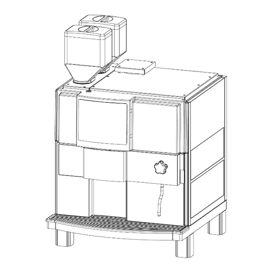
Page 15: Model 2500S Overview Diagram
Section 1: Model 2500s/i Overview 3025-001A Model 2500s Overview Diagram Concordia 2500s/i Technical Support Manual 2900-233... -
Page 16: The Model 2500S/I Components
Section 1: Model 2500s/i Overview 3025-001A The Model 2500s/i Components Touch Pad The touch pad provides a user interface for selecting and pouring drinks. Electrical Encosure The electrical enclosure houses the CPU, AC board, and DC board. Bean Hoppers Each bean hopper holds approximately 2lbs of whole beans, and feeds the beans to the grinders. -
Page 17: Section 2 :: Installation And Removal
Section 2 :: Installation and Removal Installation Requirements Dimensions Installation Starting the Machine Consumables Calibration Customer Training Installation Checklist Removal Procedures... -
Page 18: Installation Requirements
25”H x 11”W x 5.25”D Connection for ¾” drain dose Drain Indirect drain required Located within five (5) feet of machine Ambient Air Temperature Maximum ambient temp: 90°F Concordia 2500s/i Technical Support Manual 2900-233... -
Page 19: Dimensions
Section 2: Installation and Removal 3025-002A Dimensions Concordia 2500s/i Technical Support Manual 2900-233... -
Page 20: Installation
Configuring the Machine for Supply Voltage Before connecting machine to the electrical supply, check and verify the incoming power supply. The following chart displays the required voltages. 2500s/i Equipped with 4 prong 220 volt plug Required Receptacle Voltages Connections Voltage... -
Page 21: Setting The Dc Jumper Plug
: Ensure the board is fully seated by firmly pressing the board into the connector on the backplane. 7. Re-install the electrical enclosure cover and verify the display cable is not stressed, pinched or cut when the front panel is lowered Concordia 2500s/i Technical Support Manual 2900-233... -
Page 22: Configuring Transformer Auxiliary Connector #1
VOLTAGE RANGE SETTING SETTING 200 – 204 NO ADJUSTMENT 205 – 214 NO ADJUSTMENT 215 – 224 220-240 #3 GREEN WIRE 225 – 234 220-240 #4 WHITE WIRE 235 – 244 220-240 #2 ORANGE WIRE Concordia 2500s/i Technical Support Manual 2900-233... -
Page 23: Connecting The Drain
Connecting Drain WRONG INCORRECTLY INSTALLED DRAIN RIGHT CORRECTLY INSTALLED DRAIN Concordia 2500s/i Technical Support Manual 2900-233... -
Page 24: Connecting The Water Supply
Problems with Reverse Osmosis Water System A fresh water bypass is required for sites with a reverse osmosis filter system. Machine water level sensors are inoperative when used with this system. Concordia 2500s/i Technical Support Manual 2900-233... -
Page 25: Connecting The Water Treatment System
(5) feet of machine. Dimensions: 25”H x 11” W x 5.25” D Mount the system as close as possible to the machine Flush the cartridge for five minutes prior to connecting to machine Scalex Water Treatment System Concordia 2500s/i Technical Support Manual 2900-233... -
Page 26: Starting The Machine
Refer to Section 4: Software, for complete calibration instructions. Customer Training Complete customer training is required at the time of installation. Refer to Section 11: Customer Service and Training Section, for complete customer training instructions. 2-10 Concordia 2500s/i Technical Support Manual 2900-233... -
Page 27: Installation Checklist
Section 2: Installation and Removal 3025-002A Installation Checklist The installation checklist must be completed and faxed to Concordia within 24 hours of installation. Concordia 2500s/i Technical Support Manual 2-11 2900-233... -
Page 28: Removal Procedures
H. Clean and dry all interior and exterior surfaces (refrigeration unit, brew group area, drain tray, etc.) Store the bean hoppers and lids inside the refrigeration unit J. Ensure the Operator’s Manual and Quick Reference Guide are included with the unit 2-12 Concordia 2500s/i Technical Support Manual 2900-233... -
Page 29: Preparation For Shipping
Concordia for additional shipping requirements. Packaging for Shipment Packaging for Shipment Ship the machine using Concordia-supplied pallet and shipping supplies. Ship the machine using Concordia-supplied pallet and shipping supplies. If necessary, contact Concordia to request a shipping kit. If necessary, contact Concordia to request a shipping kit. - Page 30 (refer to diagram below), through the holes in the pallet and strapped down with the clips to hold the machine in place. and strapped down with the clips to hold the machine in place. BANDING STRAPS FRAGILE Side View 2-14 Concordia 2500s/i Technical Support Manual 2900-233...
-
Page 31: Section 3 :: Electrical
Section 3 :: Electrical Electrical Block Diagram Fuses Backplane AC Drawer Assembly Transformer Operating Voltage Power Into the Machine DC Power Supply Board LEDs Jumper Plug Connector Detail 10. Heater Element Wiring Diagrams... - Page 32 Chip #3 Chip #1 Chip #2 Motor Motor DC Voltage Fuse MINI-BACKPLANE P4 Fuse # on DC Board CP U Display Jumper Plug on Back Board Gate Plane Valv e F16 F17 F16 F17 Concordia 2500s/i Technical Support Manual 2900-233...
-
Page 33: Fuses
Transducer, Display, CPU, Analog Board, Steam Tank, Level Sensor Fans, Valves, Relays, Main AC Contactor Group Motors Rear Grinder Panel Four 20amp ceramic fuses protect the machine in the Block event the heating elements short out Concordia 2500s/i Technical Support Manual 2900-233... -
Page 34: Backplane
DC Power Supply Board Output Board DC Power Supply Board Input from Transformer DC Input/Output Signals for Grinders and AC Drawer Pum p M ounts below Backplane Connects to AC Board/Drawer Relays Power In Heating Elem ents Concordia 2500s/i Technical Support Manual 2900-233... -
Page 35: Ac Drawer Assembly
Single Phase: Two Relays Triple Phase: Three Relays High Leg: One Relay Diagram is Single Phase configuration. Prior to the year 2001, all domestic machines use Mercury Contactors instead of Relays. Concordia 2500s/i Technical Support Manual 2900-233... -
Page 36: Transformer
30.0vac 38vdc White 10.3vac 11vdc Yellow Fuse Gray Ref 5vdc & 9.3vac Black SECONDARY 15 Pin Transformer Plug ORANGE 240 AUXILIARY GREEN 220V PRIMARY WHITE WHITE 230V BLUE TRANSFORMER BROWN 4 Pin Transformer Plug Concordia 2500s/i Technical Support Manual 2900-233... -
Page 37: Operating Voltage
All remaining components operate on DC voltage All control voltage is DC Valves All water and steam valves on the Model 2500s/i function using a negative switching circuit. Voltage is always present at these components. The drives for the valves are located on CPU board; the CPU provides the ground to close the circuit and energize the valve. -
Page 38: Electrical Enclosure Fan
Electrical Enclosure Power switch AC drawer DC power supply board LED display on DC power supply CPU boards LED display on CPU CPU buttons Backplane Line voltage test receptacle Electrical enclosure fan Concordia 2500s/i Technical Support Manual 2900-233... -
Page 39: Power Into The Machine
The DC power supply board converts the AC voltages to many legs of DC voltage • DC voltages are distributed through the backplane, through JP4 • The backplane distributes voltage to the rest of the machine Concordia 2500s/i Technical Support Manual 2900-233... -
Page 40: Power Into Ac Components
: Ensure the board is fully seated by pressing firmly on board Re-install the e lectrical enclosure cover and verify display cable is not stressed, pinched or cut when front panel is lowered 3-10 Concordia 2500s/i Technical Support Manual 2900-233... -
Page 41: Set Transformer Auxiliary Connector #1
6. Reinstall the back panel and proceed with machine installation Transformer is accessible from the back of the machine CONNECTORS #2, #3, #4 AUXILIARY ORANGE 240V CONNECTOR #1 GREEN 220V WHITE WHITE 230V BLUE TRANSFORMER BROWN Concordia 2500s/i Technical Support Manual 3-11 2900-233... -
Page 42: Dc Power Supply Board Leds
Controlled Sensors, Flowmeter Current 11vdc± Non Fused Refrigeration Unit Chip 1 4amp 11vdc± Non Fused Refrigeration Unit Chip 2 4amp 11vdc± Non Fused Refrigeration Unit Chip 3 4amp -12vdc CPU, Display and Transducer 3-12 Concordia 2500s/i Technical Support Manual 2900-233... -
Page 43: Solid State Relays
STEAM TANK ELEMENTS Power In from AC Drawer (For Steam Tank Elements) To Steam Tank Elements To Water Tank Elements Power In from AC Drawer WATER TANK ELEMENTS (For Water Tank Elements) Concordia 2500s/i Technical Support Manual 3-13 2900-233... -
Page 44: Jumper Plug Connector Detail
Section 3: Electrical 3025-003A Jumper Plug Connector Detail Jumper Plug 1 BACKPLANE JP10 Power In P1 CONNECTOR DE TAIL (viewed from back of machine) 3-14 Concordia 2500s/i Technical Support Manual 2900-233... -
Page 45: Jumper Plug 2
Section 3: Electrical 3025-003A BACKPLANE Jumper Plug 2 JP10 Power In Jumper Plug 3 BACKPLANE JP10 Power In Concordia 2500s/i Technical Support Manual 3-15 2900-233... -
Page 46: Jumper Plug 6
Section 3: Electrical 3025-003A Jumper Plug 6 BACKPLANE JP 6 CONNECTOR DETAIL JP10 Power In Jumper Plug 7 BACKPLANE JP10 Power In 3-16 Concordia 2500s/i Technical Support Manual 2900-233... -
Page 47: Jumper Plug 7
Section 3: Electrical 3025-003A Jumper Plug 8 BACKPLANE JP10 Power In Jumper Plug 10 BACKPLANE JP10 Power In Concordia 2500s/i Technical Support Manual 3-17 2900-233... -
Page 48: Jumper Plug 9
Section 3: Electrical 3025-003A Jumper Plug 9 FROM TRANSFORMER FROM JP9 PASSES THRU TRANSFORMER BACKPLANE FROM P1 CONNECTOR BACKPLANE JP10 Power In 3-18 Concordia 2500s/i Technical Support Manual 2900-233... -
Page 49: Heater Element Wiring Diagrams
The water and steam tank heating elements must be wired in relation to the voltage configuration supplied to the machine. e. Nominal AC Voltage Nominal AC Voltage Wiring Scheme 200-208 Three Phase 208 Single Phase 220 Single Phase 240 Single Phase Concordia 2500s/i Technical Support Manual 3-19 2900-233... - Page 50 Section 3: Electrical 3025-003A Page Intentionally Left Blank 3-20 Concordia 2500s/i Technical Support Manual 2900-233...
-
Page 51: Section 4 :: Software
Section 4 :: Software Software Overview Software Quick Reference Table CPU Board Calibration Overview How to Calibrate Espresso Espresso Extraction Pre-Treatment Options Setting Milk and Water Timings... -
Page 52: Software Overview
Section 4: Software 3025-004A Software Overview The Model 2500s/i is programmable to meet the customer’s specific drink requirements. Main Menu Categories CUMULATIVE TOTAL Displays the total number of drinks poured. CUMULATIVE STATISTICS Displays the total number of drinks poured, by drink type. -
Page 53: The Service Switch
To navigate through the menu system, use the unmarked buttons near the display. The main menu category appears in the center of the screen. 2500s Touch Pad Menu Navigation 2500i Touch Pad Menu Navigation Concordia 2500s/i Technical Support Manual 2900-233... -
Page 54: Accessing The Main Menu
To exit the main menu category, press any drink button on the keypad. Modifying a Value To change a submenu value, access the desired submenu category, and press the INCREASE VALUE or DECREASE VALUE button. The value is automatically stored. Concordia 2500s/i Technical Support Manual 2900-233... -
Page 55: Accessing Cumulative Drink Statistics
The cumulative drink total is only reset through the installation of a new CPU. NOTE: Concordia requires that you record the cumulative drink statistics at the start and end of each service call. This information is required to close the service call. -
Page 56: Software Quick Reference Table
Start Time-Hours Start Time-Minutes DEFAULT SETTING Clock Set-Hours FOR AUTO START CURRENT Clock Set-Minutes TIME IS 6:30AM Clock Set-Day Clock Set-Month Clock Set-Year Daylight Savings Time Auto Rinse Time 10 MIN OFF, 3-30 MIN Concordia 2500s/i Technical Support Manual 2900-233... - Page 57 WATER VOLUME 2500i 2500s Setting Single 35mL Single 45mL Double 70mL Double 75mL Triple 105mL Americano 310mL Americano 300mL Large Americano 400mL Double Americano 310mL Americano Bypass ON/OFF Hot Water 8 sec 1 sec Concordia 2500s/i Technical Support Manual 2900-233...
- Page 58 $0.05 Large Latte $2.50 $10.00 $0.05 Cappuccino $2.00 $10.00 $0.05 Large Cappuccino $2.50 $10.00 $0.05 Milk $2.00 $10.00 $0.05 Large Milk $2.50 $10.00 $0.05 Hot Water $0.00 $10.00 $0.05 Extra Shot $0.50 $10.00 $0.05 Concordia 2500s/i Technical Support Manual 2900-233...
- Page 59 PRESS CPU SWITCH #2 TO LOAD DEFAULTS Reset PM PRESS CPU SWITCH #2 TO RESET PM COUNTER Default Setting Adjustable By Refer Config TWO TRAYS ONE TRAY/TWO TRAY Auto Milk Select ON/OFF Country US/JAPAN/KOREA Concordia 2500s/i Technical Support Manual 2900-233...
- Page 60 Lower Steam Probe Milk Level DISPLAY ANALOG/DIGITAL CIRCUIT BOARD A/D Reference VALUE DISPLAY CURRENT ACROSS REFER CHIPS MIN Refr Current REFER CURRENT 10.0 AMPS – MAX 14.5 AMPS Front Panel Grnds Bin Switch Pager Output 4-10 Concordia 2500s/i Technical Support Manual 2900-233...
-
Page 61: Cpu Board
Green LED: power to CPU board IMPORTANT: To clear software, press buttons one and four simultaneously when turning the machine on. This BUTTONS Contact function is permanent and cannot be undone. Concordia before performing this function. Concordia 2500s/i Technical Support Manual 4-11 2900-233... - Page 62 During servicing, it is sometimes useful to brew group Initialize brew group inhibit brew group initialization on startup. initialization Bypass validation of application code Bottom -or- Reserved Force software load (if (no current function) button #1 is simultaneously pressed) 4-12 Concordia 2500s/i Technical Support Manual 2900-233...
-
Page 63: Calibration Overview
If the customer changes beans, the machine must be re-calibrated. The Extraction Goal The goal when calibrating the Concordia Model 2500s/i is to extract a double espresso shot in 16-22 seconds. Espresso Extraction & Temperature Parameters Once the machine has been calibrated, measure extraction time and drink temperatures to verify they are within operating parameters. -
Page 64: How To Calibrate Espresso
Before you start Step 3, a few things you should know… Espresso Grounds Ground espresso roast beans should have a texture between table salt and flour. The specific texture will ultimately depend on the grind. The grounds should be uniform in size. 4-14 Concordia 2500s/i Technical Support Manual 2900-233... -
Page 65: Step 3: Adjust The Coffee Grind Texture
3. Pour double espresso shots until the GRIND ADJUST arrow changes direction OR the dash appears in the display (indicating the CPU detects that the amount of coffee in the brew chamber equals the COFFEE POWDER DOSE setting). Concordia 2500s/i Technical Support Manual 4-15 2900-233... -
Page 66: Step 4: Ask Customer To Approve Extraction
Step 5: Coffee Powder Dose and Water Volume are adjustable per customer request If necessary, or if requested by the customer, the coffee powder dose and water volume can be adjusted to achieve the desired results. 4-16 Concordia 2500s/i Technical Support Manual 2900-233... -
Page 67: Espresso Extraction Pre-Treatment Options
This pre-infusion process enhances the quality of the espresso shot. The Model 2500s/i has seven pre-treatment options, each varying in the specific pressure used to pack the ground beans, the amount of water used to pre-infuse, and the wait time between the pre-infusion and the brewing. - Page 68 3. A 3-second delay before brewing PRE-TREATMENT #7 1. Pressure on the ground coffee is slightly increased 2. Espresso grounds are pre-infused for 4/10 of a second 3. A 4-second delay before brewing 4-18 Concordia 2500s/i Technical Support Manual 2900-233...
-
Page 69: Setting Milk And Water Timings
The purpose of the cappuccino coffee delay is to allow the foamed milk to be delivered to the cup first, followed by the delivery of the espresso. This results in a better separation of coffee and milk. Concordia 2500s/i Technical Support Manual 4-19 2900-233... - Page 70 Section 4: Software 3025-004A Page Intentionally Left Blank 4-20 Concordia 2500s/i Technical Support Manual 2900-233...
-
Page 71: Section 5 :: Plumbing
Section 5 :: Plumbing Water System Water Supply Water Pump & Motor Flowmeter Water Tank Valves Water Level Sensors The Steam System Steam Valves... -
Page 72: Water System
Section 5: Plumbing 3025-005A Water System 2500s & 2500i Hydraulics Diagram Concordia 2500s/i Technical Support Manual 2900-233... -
Page 73: Water Supply
The back-flow prevention device (check valve) is required by many state and local health codes and inhibits reverse water flow into the water supply. Water Filtering Water Filtration System The Scalex® Water Treatment System includes a carbon filter cartridge and water softener cartridge. Concordia 2500s/i Technical Support Manual 2900-233... -
Page 74: Water Pump And Motor
Viewing Pump Pressure 1. Enter the programming menu and access the main menu category: TEST ROUTINES 2. Scroll to the submenu category: WATER PUMP 3. Activate the pump. The water gauge will display current pump pressure. Concordia 2500s/i Technical Support Manual 2900-233... -
Page 75: Changing Pump Pressure
2. Scroll to the submenu category: BREW WATER VALVE 3. Activate the valve. The display will read 0mL and the amount will increase as the valve is opened and water flows through the flowmeter. Concordia 2500s/i Technical Support Manual 2900-233... -
Page 76: Check Water Flow Message
If the water level in the tank is low and the circuit is open, the CPU activates the brew water valve, allowing line pressure to fill the tank. The heating elements are then inhibited. Water Tank and Level Probe Not Grounded LOW WATER Concordia 2500s/i Technical Support Manual 2900-233... -
Page 77: Temperature Probe
The pressure relief valve functions as a safety relief valve. If the pressure in the water tank exceeds 175psi, the pressure relief valve opens to release excess pressure. A drain hose is routed from the pressure relief valve to the drain tray. Concordia 2500s/i Technical Support Manual 2900-233... -
Page 78: Drain Valve
The hot water and steam fill valve configuration is the same for both the 2500i and 2500s. Concordia 2500s/i Technical Support Manual 2900-233... -
Page 79: Water Level Sensors
Section 5: Plumbing 3025-005A Water Level Sensors With the dual level sensors, the Model 2500s/i can detect between low water and no water. The heating elements remain on during the steam fill, resulting in faster recovery times during fill periods. -
Page 80: Steam Tank Fill Valve
Verifying the Water Level Probes in the Steam Tank 1. Enter the programming menu and access the main menu category: TEST ROUTINES 2. Scroll to the submenu category: UPPER STEAM PROBE 3. WET is displayed if probe is seeing ground 5-10 Concordia 2500s/i Technical Support Manual 2900-233... -
Page 81: Pressure Gauge
Rated at 260°F In the event that the steam tank should overheat, the high temperature limit switch cuts the 24vdc control signal to the solid state relays, which opens the circuit to the heating elements. Concordia 2500s/i Technical Support Manual 5-11 2900-233... -
Page 82: Steam Valves
Steam is routed directly to the milk valve. Steam Wand Valve (if present) The steam wand valve is a manually operated valve to allow for steaming milk in a pitcher. 5-12 Concordia 2500s/i Technical Support Manual 2900-233... -
Page 83: Captive Water Purge System
The steam tank allows water in, but only steam exits the tank causing a build-up of scale inside the tank that can dramatically affect the tank performance. The Model 2500s/i water purge valve opens daily during each brew clean cycle, flushing 0.3 liters of water through the system to remove any sediment. - Page 84 Section 5: Plumbing 3025-005A Page Intentionally Left Blank 5-14 Concordia 2500s/i Technical Support Manual 2900-233...
-
Page 85: Section 6 :: The Coffee System
Section 6 :: The Coffee System Coffee System Overview Grinders Bean Hoppers... -
Page 86: Coffee System Overview
Only espresso roast beans can be used in the Model 2500s/i. The Espresso Path With ground beans in the brew chamber, the chamber is sealed and hot water (195°F/85°C) at 140psi is forced through the ground beans and... -
Page 87: Grinders
The grinder adjustment panel is located behind the front panel. The grinder adjust screw is connected via cable to the grinder adjust worm gear located on each grinder. Concordia 2500s/i Technical Support Manual 2900-233... -
Page 88: Grinder Adjustment Panel
• Turning the grinder adjustment screw counter-clockwise increases the gap between the upper and lower burrs, resulting in a coarser grind, decreasing the extraction time Grinder Adjustment Diagram Concordia 2500s/i Technical Support Manual 2900-233... -
Page 89: Coffee Powder Channel
When reinstalling the grinder, ensure the electrical harness wires are not trapped under the grinder bottom plate. Replacing Grinder Burrs/Blades From time to time, grinder burrs/blades become worn and dull and need to be replaced. Concordia 2500s/i Technical Support Manual 2900-233... -
Page 90: Setting Grinder Adjustment Indicator To Mid-Scale
CABLE FRONT GRINDER SCREW FINE COARSE CW = FINE CCW = COARSE FINE COARSE Adjust the grinder to the desired grind. It may be necessary to reset the indicator to mid-scale a second time. Concordia 2500s/i Technical Support Manual 2900-233... -
Page 91: Bean Hoppers
2. Push the hopper stopper into the hopper, to the indicator line 3. With the hopper stopper in place, you can remove a full hopper from the machine HOPPER LID HOPPER HOPPER STOPPER Concordia 2500s/i Technical Support Manual 2900-233... - Page 92 Section 6: The Coffee System 3025-006A Page Intentionally Left Blank Concordia 2500s/i Technical Support Manual 2900-233...
-
Page 93: Section 7 :: Milk System And Refrigeration Unit
Section 7 :: Milk System and Refrigeration Unit Milk System Overview Milk Delivery System Overview The Milk Delivery System Components Air Gate Valve Assembly Alt Milk Valve Understanding the Relationship Between Steam Temperature and Milk Temperature The Milk Delivery System The Refrigeration Unit Refrigeration Cooling Module Assembly 10. -
Page 94: Milk System Overview
The interior design of the milk valve is a Venturi. This design causes the milk, air, and steam to mix and expand as it travels through the milk valve. The result is hot, frothy milk delivered to the cup. Milk Delivery System Overview Concordia 2500s/i Technical Support Manual 2900-233... -
Page 95: The Milk Delivery System Components
, a food-grade lubricant. Lubricating the ® plunger ensures smooth operation of the plunger. Also, the milk valve plunger is momentarily activated after one hour of inactivity, to reduce the potential for a sticking milk valve plunger. Concordia 2500s/i Technical Support Manual 2900-233... -
Page 96: Nozzle And Anti-Splatter Shield
Milk #1 (front) container. When the NON-FAT option is selected, the valve is not activated, and milk is drawn from the Milk #2 (rear) container. Concordia 2500s/i Technical Support Manual 2900-233... -
Page 97: The Latte Pour Process
There will be less contact time between the milk and steam, and this will result in the temperature of the delivered milk being cooler. Steam Temperature = Milk Temperature Concordia 2500s/i Technical Support Manual 2900-233... -
Page 98: Troubleshooting And Repair
If neither of these steps resolves the issue, verify the operation of the air gate valve and repair or replace. Possible Alternate Cause The milk valve plunger may be stuck. Check the plunger and lubricate or replace as necessary. Concordia 2500s/i Technical Support Manual 2900-233... -
Page 99: The Milk Delivery System
Section 7: Milk System and Refrigeration Unit 3025-007A The Milk Delivery System The Model 2500s/i features an on-board refrigeration unit to house the milk used for drinks. The refrigeration unit is designed to accommodate two standard off-the-shelf 1-gallon milk containers. -
Page 100: The Refrigeration Unit
Section 7: Milk System and Refrigeration Unit 3025-007A The Refrigeration Unit Refrigeration Unit Overview Diagram Concordia 2500s/i Technical Support Manual 2900-233... -
Page 101: Refrigeration Cooling Module Assembly
Viewing the current (amperage) draw of the cooling/refer module assembly 1. Enter the programming menu and access the main menu category: TEST ROUTINES 2. Scroll to the submenu category: REFR CURRENT 3. The current amperage across refer chips is displayed Concordia 2500s/i Technical Support Manual 2900-233... -
Page 102: Cold Sink Deflector
1. A gap between the CSD and the circulation fan 2. An improperly positioned CSD (e.g. a CSD allowed to rest on the floor of the refrigeration unit) Cold Sink Deflector (CSD) Interior Side View Upper Refrigeration Unit 7-10 Concordia 2500s/i Technical Support Manual 2900-233... -
Page 103: Fans
The temperature probe is used to measure the internal temperature of the refrigeration unit. The CPU monitors the temperature and adjusts the interior temperature through powering the Peltier chips in the refrigerator cooling module. Concordia 2500s/i Technical Support Manual 7-11 2900-233... -
Page 104: Exterior Cooling Module Fan Assembly
The exterior refrigerator fan assembly, located on the exterior rear of the refrigerator cooling module unit, is used to dissipate heat from the heat sink side of the cooling module. External Fridge Fan Assy PN 2310-030 7-12 Concordia 2500s/i Technical Support Manual 2900-233... -
Page 105: Milk Weight Trays
Section 7: Milk System and Refrigeration Unit 3025-007A Milk Weight Trays The milk level system on the Model 2500s/i has two milk weight trays, so each milk container is weighed independently. Milk levels are monitored using the milk weight trays, and a notification message will appear when milk levels are low or empty. -
Page 106: Adjusting The Milk Weight Tray
To adjust the milk weight tray, simply turn the adjustment screw until the display reads 60. Ensure the milk weight tray is properly located within the refrigeration unit prior to adjustment. 7-14 Concordia 2500s/i Technical Support Manual 2900-233... -
Page 107: Milk Level Sensors
Auto Milk Select The auto milk select feature can be enabled or disabled. This feature is in the SPECIAL FEATURES category on the Model 2500i, and in the MISCELLANEOUS category on the Model 2500s. Auto Milk Select enabled: • If one of the milk containers is empty, the machine will automatically draw milk from the other container. -
Page 108: Troubleshooting And Repair
3. With the milk weight tray(s) in place, with no milk in the refrigerator, the display should read 60 ± 1 With a full container of milk placed on milk weight tray, the displa should read approximately 185 ± 10 7-16 Concordia 2500s/i Technical Support Manual 2900-233... -
Page 109: Section 8:: Brew Group
Section 8:: Brew Group The Brew Group Hall-Effect Sensors Piston Movement Group Initialization Measuring Coffee Powder Dose Motors Pistons Piston Removal Procedures Gearbox Removal and Installation... - Page 110 Brew Group Overview Brew Group Overview Two 38vdc motors drive the Model 2500s/i’s double-piston brew group. Two 38vdc motors drive the Model 2500s/i’s double-piston brew group. Grounds Funnel Hot Water Tank Grounds Chute Left “Coffee”...
-
Page 111: Hall-Effect Sensors
(.089”). For reference, a credit card is approximately 1.5mm. Right Brew Piston Brew Chamber Left Coffee Piston Fixed Hall Effect Sensor Fixed Hall Effect Sensor Magnet Passes by Sensor As piston moves up Magnet Passes by Sensor As piston moves up Concordia 2500s/i Technical Support Manual 2900-233... -
Page 112: Piston Movement
Right Brew Piston Brew Chamber Left Coffee Piston 68 Upper “Crash” Upper “Crash” 370-379 Home Position 358-364 102-68 Hall-Effect Sensor Hall-Effect Sensor 100-71 Lower “Crash” 80-71 362-363 Home Position Magnet 487- 447 Lower “Crash” Concordia 2500s/i Technical Support Manual 2900-233... -
Page 113: Group Initialization
“L” will appear on the display and the sensor LED will illuminate Group Initialization Each time the Concordia Model 2500 is turned on, the brew group runs through 22 different steps to perform a self-calibration. The CPU monitors the coffee piston movement from the base of the brew chamber to the base of the brew piston. -
Page 114: Motors
A set of rotational Hall-Effect Sensors located within the motor send electronic pulses to the CPU. The CPU correlates “X” pulses of motor rotation to piston movement. NOTE : The left and right motors are not interchangeable because they contain different worm drive gears. Concordia 2500s/i Technical Support Manual 2900-233... -
Page 115: Pistons
The left piston is also referred to as the coffee piston or the lower piston. When coffee is ground and delivered into the brew chamber, the left piston moves up to pack the coffee against the right brew piston. Concordia 2500s/i Technical Support Manual 2900-233... -
Page 116: Right Piston
During an extraction, the brew water passes through this upper piston, through the ground coffee, through the brew piston, and out of the brew chamber via tubing to be dispensed into the cup. Concordia 2500s/i Technical Support Manual 2900-233... -
Page 117: Piston Removal Procedures
11. Using TEST ROUTINES, drive the right assembly drive down, allowing the helical bolt to be re-inserted and tightened. 12. Reinstall the upper piston assembly. 13. Verify the brew group operates correctly. 14. Reinstall the top panel and bean hoppers. Concordia 2500s/i Technical Support Manual 2900-233... -
Page 118: Gearbox Removal And Installation
NOTE: Make sure the right positional Hall-Effect Sensor plate has been properly placed. 6. Press the down arrow until the gearbox is drawn up to the brass spacers. 8-10 Concordia 2500s/i Technical Support Manual 2900-233... - Page 119 8. Insert the four gearbox mounting bolts up through the gearbox and finger-tighten. 9. Lower the left and right pistons slightly and tighten the four mounting bolts. 10. Run a brew group initialization to reset. 11. Re-install the grounds chute. Concordia 2500s/i Technical Support Manual 8-11 2900-233...
- Page 120 Section 8: The Brew Group 3025-008A Page Intentionally Left Blank 8-12 Concordia 2500s/i Technical Support Manual 2900-233...
-
Page 121: Section 9 :: Cleaning And Maintenance
Section 9 :: Cleaning and Maintenance Daily Maintenance of the Concordia Espresso Machine Preventive Maintenance... -
Page 122: Daily Maintenance Of The Concordia Espresso Machine
To purchase cleaning products, call Concordia Customer Service: (800) 778-0990 Automatic shipment of cleaning products is available; advise customer to call Concordia Customer Service for information on the auto-ship program. The chemicals in the cleaning products can bleach clothing and countertops, and must be used with care. -
Page 123: Auto-Rinse
Any repairs or replacement of parts not covered by the PM call instructions must be scheduled as a Corrective Maintenance (CM) call through Concordia Coffee Systems (in the U.S.A. call: (800) 778-0900). PM Kits There are separate PM kits for the 10K drink cleaning (part #5000-013), and for the 30K supplement drink cleaning (part #5000-015). -
Page 124: Preventive Maintenance Checklist
ELECTRICAL ENCLOSURE Steamed Milk: 145° - 165°F _________________ Degrees AC DRAWER Foamed Milk: above 130°F __________________ Degrees LATTE TEMPERATURE___________________ Degrees CAPP TEMPERATURE ____________________ Degrees DRINK LEVELS Part 11: Reset PM Counter RESET PM COUNTER Concordia 2500s/i Technical Support Manual 2900-233... -
Page 125: Section 10 :: Concordia Procedures
Section 10 :: Concordia Procedures Concordia Coffee Systems Service Call Process Complete Call Protocol Service Call Checklist Parts Return Policy... -
Page 126: Concordia Coffee Systems Service Call Process
Do not spread tools and parts around in the business Respect the customers business while you repair their machine Record current quantity on hand of Concordia cleaning products, recommend ordering or signing up for auto-shipment of cleaning products if account is low on supplies... -
Page 127: Complete Call Protocol
Section 10: Concordia Procedures 3025-010A Complete Call Protocol On each service call, Concordia requires the entire machine be inspected to ensure continued operation. Machine Appearance Interior/Exterior reasonably clean Milk Valve Cleanliness: ZERO INTERNAL BUILD-UP Calibration: Proper temp and levels Lubricate plunger with SuperLube ®... -
Page 128: Service Call Checklist
Section 10: Concordia Procedures 3025-010A Service Call Checklist • Each Service Call Concordia requires the system inspection to ensure continued operation. Concordia’s Call Checklist is designed to reduce repeat calls and increase customer satisfaction. • A completed Service Call Checklist must be submitted with each service invoice. -
Page 129: Parts Return Policy
(as shipped from Concordia). The parts warranty from Concordia is for 90 days. This applies to both for new machines and for replacement parts. Concordia has determined that some items that are consumable and do not need to be returned, but they must have a Return Authorization Form (RA Form). -
Page 130: Return Material Tag
Each part must have a Return Material Tag filled out properly. If the tag is not complete, parts will not be replaced or credited. A 15% handling fee will be charged for any tags or forms not filled out completely. 10-6 Concordia 2500s/i Technical Support Manual 2900-233... -
Page 131: Return Material Authorization Form
4. The part number of the part being returned and quantity 5. A description of the part being returned 6. After filling out the RMA form, fax or email it back to Concordia to receive an RMA number for the returned parts 7. -
Page 132: Form: Return Material Authorization
Form: Return Material Authorization RMA# : PARTS USAGE SO# : CUSTOMER : FOR THE WEEK Office use CUSTOMER # ENDING : only Serial Call Number Number Date of Removal Part Number Part Description PO # 10-8 Concordia 2500s/i Technical Support Manual 2900-233... -
Page 133: Section 11 :: Customer Service And Training
Section 11 :: Customer Service and Training Training the Customer Concordia Coffee Systems’ Value Added Service G.U.E.S.T. -
Page 134: Training The Customer
Section 11: Customer Service & Training 3025-011A Training the Customer Concordia requires complete customer training at the time of installation. Cleaning instructions should be reviewed during each service call. Customer Training Includes Use of Quick Reference Guide Start Machine Filling Machine with Beans and Milk... -
Page 135: Accessing Programming Menu
Correct placement of the milk pick-up tubes Checking the air filter Un-sticking the door latch Calling Concordia for Assistance Review the location of the Concordia 800 number and advise the customer to call Concordia with any questions about their new machine. Concordia 2500s/i Technical Support Manual... -
Page 136: Concordia Coffee Systems' Value-Added Service
Technicians are the ambassadors of the companies they represent. As a technician servicing Concordia machines, you will see Concordia customers on average 3 to 5 times per year; more than any other representative of Concordia. -
Page 137: Greet The Customer
How you greet the custome r sets the tone the entire service call. The remainder of the communication, for both today’s service call and future service calls, will be affected by this initial meeting with the customer. Concordia 2500s/i Technical Support Manual 11-5 2900-233... -
Page 138: Understand Your Customer
“Hi, I’m Alex with Awesome Service XYZ Company, is Bob here? He reported a problem with your Concordia espresso machine.” (going to get caller) “Hi Bob, (Hand out bus iness card if you h ave one) I’m Alex with Awesome Service XYZ Company . -
Page 139: Empathize With Your Customer
I understand how you feel. I would feel the same way under those circumstances. appreciate your situation. I would not like that to happen to me. Let me see what I can do to resolve this for you. Concordia 2500s/i Technical Support Manual 11-7 2900-233... -
Page 140: Solve The Problem
Airflow around the re-circulating fans Keeping the refrigeration compartment free of foreign objects Changing water filter/softener cartridges at regular intervals Simple lubrication points Daily cleaning requiremen lways end your conversation by thanking the customer for their business. 11-8 Concordia 2500s/i Technical Support Manual 2900-233... -
Page 141: Section 12 :: Messages
Section 12 :: Messages Troubleshooting Display Messages... -
Page 142: Troubleshooting Display Messages
Pre-treatment too high Lower pre-treatment setting. Verify flowmeter wiring is correct. Faulty flowmeter. Using TEST ROUTINES / BREW WATER VALVE, verify counter increments. Pump pressure. Ensure flowmeter is not clogged. Verify pump calibration. 12-2 Concordia 2500s/i Technical Support Manual 2900-233... - Page 143 No power to grinder. Check fuses in AC drawer. BEANS Verify milk level. OUT OF MILK Front milk count is 75 or Verify milk weight tray is properly FRONT lower. installed and calibrated. Concordia 2500s/i Technical Support Manual 12-3 2900-233...
- Page 144 41°F. REFR TEMP Check external refrigerator fan XX.X F Refrigerator temperature filter. where xx.x exceeds NSF-specified Check refrigeration components. is the Keep refrigerator door closed for maximum (41°F). current two hours minimum. temperature 12-4 Concordia 2500s/i Technical Support Manual 2900-233...
- Page 145 Check using CHECK TEMPS / Pressure transducer STEAM TEMP. STEAM TEMP failure. Failed transducer = 278.6°F (137°C). Steam temp setting higher Check using TEMP SETTING / than STEAM HI setpoint. STEAM HI. Concordia 2500s/i Technical Support Manual 12-5 2900-233...
- Page 146 Short circuit on water tank WATER TEMP. temp sensor. Shorted sensor = 256.8°F WATER (124.8°C). TEMP HI Brew water temp setting Check using TEMP SETTING / BREW higher than Brew Water Hi WATER HI. set point. 12-6 Concordia 2500s/i Technical Support Manual 2900-233...
- Page 147 210°F (98.9°C). Heating element failure. Check heating element. Brew Water temp setting Check using TEMP SETTING / BREW lower than Brew Water Lo WATER LO. setpoint. Leaking pressure relief Check pressure relief valve. valve. Concordia 2500s/i Technical Support Manual 12-7 2900-233...
- Page 148 Section 12: Messages 3025-012A Page Intentionally Left Blank 12-8 Concordia 2500s/i Technical Support Manual 2900-233...
-
Page 149: Section 13 :: Troubleshooting
Section 13 :: Troubleshooting Troubleshooting Quick Reference Guide Troubleshooting Trees... -
Page 150: Troubleshooting Quick Reference Guide
No fans running and Replace blown fuse. both 24vdc Blown F18 fuse on the DC NOTE LEDs are lit power supply. : Use 5amp fuse only. on the DC power supply. 13-2 Concordia 2500s/i Technical Support Manual 2900-233... - Page 151 Water volume setting is too Verify proper setting for water high. volume. Failing of Confirm the stray voltage in sites coils or Excessive voltage in Neutral or Ground circuit. Have components control. customer resolve. in controls Concordia 2500s/i Technical Support Manual 13-3 2900-233...
-
Page 152: Milk System
Milk got too warm, then Switch to new milk supply. foam too cold Milk spraying Soak milk valve nozzle in hot water Dirty or closed milk valve during and cleaning tablets for five nozzle dispensing minutes. 13-4 Concordia 2500s/i Technical Support Manual 2900-233... -
Page 153: Troubleshooting Trees
Check pins and connectors going to CPU for possible Contact Concordia dislodged pin. Service Replace CPU as last Department for resort. further assistance. Concordia 2500s/i Technical Support Manual 13-5 2900-233... - Page 154 Calibrate grinder and Brew Line for Was the extraction for proper debris. Is either time of the 2nd extraction time. present? drink shorter than the first one? Replace defective parts and retest unit. 13-6 Concordia 2500s/i Technical Support Manual 2900-233...
- Page 155 Pin 7 on specs. JP2. Continuity Present? Inspect CPU for possible damaged traces, and check harnesses connecting to CPU for possible loose connections. Repair if any, replace CPU as last resort. Concordia 2500s/i Technical Support Manual 13-7 2900-233...
- Page 156 Is Find stress point and repair. cycle completed within 15 Possible grounds build up, or Seconds without failure? sticky lower piston orings. Run multiple drinks to test then run cleaning cycle. 13-8 Concordia 2500s/i Technical Support Manual 2900-233...
- Page 157 Is Find stress point and repair. cycle completed within 15 Possible Oblong Bushings in Seconds without failure? Right Drive. Run multiple drinks to test then run cleaning cycle. Concordia 2500s/i Technical Support Manual 13-9 2900-233...
- Page 158 Find stress point and motor. repair. Is Binding or sluggishness evident? Run Shut Down cleans, and test machine operations. Possible sticky lower piston, just needed some rinsing. 13-10 Concordia 2500s/i Technical Support Manual 2900-233...
- Page 159 Find stress point and Brass sleeve. Replace Roller repair. Is Binding or Bearings. Reinstall and test. Sluggishness evident? If sluggish operation persists, replace Right Drive Motor Replace Upper Piston o-ring, and run test drinks and cleans. Concordia 2500s/i Technical Support Manual 13-11 2900-233...
- Page 160 To Identify the CPU look at the back side, and you should see Yellow Capacitors if it is filtered. If you do not see these, the CPU is not filtered, and needs replacement. 13-12 Concordia 2500s/i Technical Support Manual 2900-233...
- Page 161 Initialization with grounds. If everything else completed without is ok, replace the CPU. failure? Machine should be operating normally. Power reset may have fixed problem. Verify "Filtered" CPU is installed. If not, replace. Concordia 2500s/i Technical Support Manual 13-13 2900-233...
- Page 162 Section 13: Troubleshooting 3025-013A Page Intentionally Left Blank 13-14 Concordia 2500s/i Technical Support Manual 2900-233...
-
Page 163: Section 14 :: Parts List & Diagrams
Section 14 :: Parts List & Diagrams Recommended Tools List Recommended Van Stock Parts List and Diagrams... -
Page 164: Recommended Tools List
3200-017 Superlube pen 3100-002 Teflon tape – ¼” 3330-013 Scotchbrite pads red 3900-007 Silicone spray 97004 Ty-wraps (1000) 1454-014 RTV silicone seal 3200-003 Water Hardness Test Strips (50) 3400-018 Stainless steel cleaner 3900-008 14-2 Concordia 2500s/i Technical Support Manual 2900-233... -
Page 165: Recommended Van Stock
SCREW- FH- PHIL- MS 8/32 X 1 1455-008 SPRING- WEIGHT TRAY 1455-012 SPRING - GAS - FRONT PANEL 1456-016 LATCH - KEY - LOCKING - FRONT PANEL 1456-017 ASSY SLIDE FRONT PAIR MOD 1456-018 LATCH - SNAP (SET) Concordia 2500s/i Technical Support Manual 14-3 2900-233... - Page 166 WATER LEVEL SENSOR PCA - STEAM TANK 2612-021 DISPLAY PCA 2630-034 DC POWER SUPPLY PCA 2630-049 ASSY - AC DRAWER 2630-066 ASSY – CPU PROGRAMMED 2500s 2630-067 ASSY – CPU PROGRAMMED 2500i 2640-029 DISPLAY- LCD 2640-043 TOUCH PAD 2000s BLACK 2640-044...
-
Page 167: Parts List And Diagrams
Group Drive System Milk Valve Assembly Product Delivery, 2500i Product Delivery, 2500s Refer Module Assembly Refer Cooling Fan Assembly Steam Tank, Front Steam Tank, Rear Steam Wand Water Pump Water Tank Water/Steam Gauge Assembly Concordia 2500s/i Technical Support Manual 14-5 2900-233... -
Page 168: Diagram 1: Overview
Section 14: Parts List & Diagrams 3025-014A Diagram 1: Overview 14-6 Concordia 2500s/i Technical Support Manual 2900-233... -
Page 169: Diagram 1, Parts List: Overview
ASSY AC DRWR SGL PHASE 2630-049 ASSY GRP/WTR TANK 2500 2130-026 CHUTE DREGS 2000 NSF 1110-335 ASSY- DREGS BIN- NSF 2220-041 ASSY FNT PNL BLACK 2500s 2640-047 ASSY FNT PANEL BLK 2500i 2640-048 ASSY WEIGHT TRAY SMALL 2310-027 PANEL SIDE RT 2.5K 1120-103 ASSY RFR MOD 6-INCH 2.5K... -
Page 170: Diagram 2: Chassis
Section 14: Parts List & Diagrams 3025-014A Diagram 2: Chassis 14-8 Concordia 2500s/i Technical Support Manual 2900-233... -
Page 171: Diagram 2, Parts List: Chassis
1410-003 PH PHIL MS 10-32 X ¼ 1410-012 PLUG- 30A NEMA L14-30 1354-011 ASSY – DRAIN BLOCK - 2000 2790-031 BLOCK- COUPLING- DRAIN O-RING- DRAIN BLOCK- NSF 1260-052 CONN- BARB- 1/2M X 3/4B Concordia 2500s/i Technical Support Manual 14-9 2900-233... -
Page 172: Diagram 3: Doors, 2500I
Section 14: Parts List & Diagrams 3025-014A Diagram 3: Doors, 2500i 14-10 Concordia 2500s/i Technical Support Manual 2900-233... -
Page 173: Diagram 3, Parts List: Doors, 2500I
BRKT MTG INSUL 2000s/i 1110-325 ASSY- DOOR INTERIOR- 2000 2510-004 FH PH MS SS UCT 4-40 X ¼ 1410-087 PH PHIL SS 6-32 X 3/16 1410-094 STRIKE FASTEX 1456-024 BRKT RFR STRIKE 1110-622 Concordia 2500s/i Technical Support Manual 14-11 2900-233... -
Page 174: Diagram 4, Doors, 2500S
Section 14: Parts List & Diagrams 3025-014A Diagram 4, Doors, 2500s 14-12 Concordia 2500s/i Technical Support Manual 2900-233... -
Page 175: Diagram 4, Parts List: Doors, 2500S
Section 14: Parts List & Diagrams 3025-014A Diagram 4, Parts List: Doors, 2500s Concordia Diagram 4 Description Available Part Item # Number ASSY- FRG DOOR W/STM 2.5KS 2510-099 ASSY DREGS BIN DOOR 2000S 1110-294 MAGNET ONLY 1311-002 PH PHIL MS SS 4-40 X ¼... -
Page 176: Diagram 5: Front Panel 2500I
Section 14: Parts List & Diagrams 3025-014A Diagram 5: Front Panel 2500i 14-14 Concordia 2500s/i Technical Support Manual 2900-233... -
Page 177: Diagram 5, Parts List: Front Panel 2500I
Slide Upgrade Kit 98430 BRKT-UPPER RT-SLIDE-2000 BRKT-UPPER LT-SLIDE 2000 BRKT-LOWER RT-SLIDE-2000 BRKT-LOWER LT-SLIDE-2000 FH PHIL MS UCT 8-32 X ¼ PH PHIL MS 8-32 X ¼ FH PHIL U/C 8-32 X 3/8 SS SLIDE-FRONT PNL-PAIR-MOD Concordia 2500s/i Technical Support Manual 14-15 2900-233... -
Page 178: Diagram 6: Front Panel 2500S
Section 14: Parts List & Diagrams 3025-014A Diagram 6: Front Panel 2500s 14-16 Concordia 2500s/i Technical Support Manual 2900-233... -
Page 179: Diagram 6, Parts List: Front Panel 2500S
Section 14: Parts List & Diagrams 3025-014A Diagram 6, Parts List: Front Panel 2500s Concordia Diagram 6 Description Available Part Item # Number ASST- FNT PNL BLACK 2500s 2640-047 PNL FRONT CAST BLACK 2000 1110-233-11 LABEL- ACORTO LOGO- AL 1500-095... -
Page 180: Diagram 7: Top Panel
Section 14: Parts List & Diagrams 3025-014A Diagram 7: Top Panel 14-18 Concordia 2500s/i Technical Support Manual 2900-233... -
Page 181: Diagram 7, Parts List: Top Panel
FH PHIL MS SS 8-32 X 1 1410-076 PNL TOP GRINDER DBL 2000 1110-296 EXHAUST FAN- 24VDC 2510-044 PIN M AMP MED 1353-009 HSG AMP 2PIN M WHT 1353-002 WASHER EXT STAR #8 1430-012 NUT HEX SS 8-32 1420-003 Concordia 2500s/i Technical Support Manual 14-19 2900-233... -
Page 182: Diagram 8: Grinder Assembly
Section 14: Parts List & Diagrams 3025-014A Diagram 8: Grinder Assembly 14-20 Concordia 2500s/i Technical Support Manual 2900-233... -
Page 183: Diagram 8, Parts List: Grinder Assembly
COUPLING- GRIND ADJ- NSF ASSY- SWITCH- MAG- 4 2510-027 BUFFER-GRINDER-M6X5/12 2240-002 PH PHIL MS 4-40 X ¼ 1410-065 TUBE CLR PVC ½ X 5/8 1250-011 STUD- BALL MOUNT 1452-004 OBS CAP GRINDER 16uF 400 2240-068 Concordia 2500s/i Technical Support Manual 14-21 2900-233... -
Page 184: Diagram 9: Grinder Adjustment
Section 14: Parts List & Diagrams 3025-014A Diagram 9: Grinder Adjustment 14-22 Concordia 2500s/i Technical Support Manual 2900-233... -
Page 185: Diagram 9, Parts List: Grinder Adjustment
1110-268 PH PHIL MS SS 6-32 X ¼ 1410-007 ASSY PNL FNT GRIND 2000 2510-054 PNL GRIND FRONT CN 1110-553 ASSY- SWITCH- MAG- 4 2510-027 PH PHIL MS SS 4-40 X 1/4 1410-065 Concordia 2500s/i Technical Support Manual 14-23 2900-233... -
Page 186: Diagram 10: Group Upper And Lower Piston Assy
Section 14: Parts List & Diagrams 3025-014A Diagram 10: Group Upper and Lower Piston Assy 14-24 Concordia 2500s/i Technical Support Manual 2900-233... -
Page 187: Diagram 10, Parts List: Group Upper & Lower Piston Assy
CARRIER- SIEVE- RR GROUP 2140-037 E-CLIP- LOWER PISTON 2140-048 KIT- LWR PISTON SIEVE 98436 O-RING- UPPER PISTON 2140-023 SEAL LOWER PISTON 2500 1260-092 RING- WIPING- LWR PISTON 1260-091 HOLDER- LWR PISTON SIEVE 2140-059 Concordia 2500s/i Technical Support Manual 14-25 2900-233... -
Page 188: Diagram 11: Group Drive System
Section 14: Parts List & Diagrams 3025-014A Diagram 11: Group Drive System 14-26 Concordia 2500s/i Technical Support Manual 2900-233... -
Page 189: Diagram 11, Parts List: Group Drive System
BOLT- DISTANCE- BRASS 2140-032 PLATE- FASTENING 2140-034 DRIVE DUAL W/SPINDLE & CAST 2130-014 SCREW- ALLEN- M6X65 2140-004 PIN- M- AMP- MED 1353-009 HSG- AMP- 3PIN M- WHT 1353-003 HSG- AMP- 4PIN M- WHT 1353-004 Concordia 2500s/i Technical Support Manual 14-27 2900-233... -
Page 190: Diagram 12: Milk Valve Assembly
Section 14: Parts List & Diagrams 3025-014A Diagram 12: Milk Valve Assembly 14-28 Concordia 2500s/i Technical Support Manual 2900-233... -
Page 191: Diagram 12, Parts List: Milk Valve Assembly
CONN LUER VENT 1000i 1232-079 VALVE 3-WAY ASCO 1212-007 ELBOW 10-32 X 1/8 BARB 1232-100 BRKT RETRO AIR VALVE 1110-395 PH PHIL SS M4X80 1410-098 FH PH MS SS UCT 4-40 X 1/8 1410-087 Concordia 2500s/i Technical Support Manual 14-29 2900-233... -
Page 192: Diagram 13: Product Delivery, 2500I
Section 14: Parts List & Diagrams 3025-014A Diagram 13: Product Delivery, 2500i 14-30 Concordia 2500s/i Technical Support Manual 2900-233... -
Page 193: Diagram 13, Parts List: Product Delivery, 2500I
Diagram 13, Parts List: Product Delivery, 2500i Concordia Diagram 13 Description Available Part Item # Number BRKT PRODUCT DELIV 2.5K 1110-566 GROM 13/32IDX1/2GDX1/16 1260-081 ASSY- NOZZLE- HOT WATER 2790-089 ASSY- NOZZLE- ESPRESSO 2790-090 Concordia 2500s/i Technical Support Manual 14-31 2900-233... -
Page 194: Diagram 14: Product Delivery, 2500S
Section 14: Parts List & Diagrams 3025-014A Diagram 14: Product Delivery, 2500s 14-32 Concordia 2500s/i Technical Support Manual 2900-233... -
Page 195: Diagram 14, Parts List: Product Outlet 2500S
Section 14: Parts List & Diagrams 3025-014A Diagram 14, Parts List: Product Outlet 2500s Concordia Diagram 14 Description Available Part Item # Number BRKT PRODUCT SGL 2KS 1110-565 GROM 13/32IDX1/2GDX1/16 1260-081 ASSY- NOZZLE- HOT WATER 2790-089 ASSY- NOZZLE- ESPRESSO 2790-090... -
Page 196: Diagram 15: Refer Module Assembly
Section 14: Parts List & Diagrams 3025-014A Diagram 15: Refer Module Assembly 14-34 Concordia 2500s/i Technical Support Manual 2900-233... -
Page 197: Diagram 15, Parts List: Refer Module Assembly
ASSY WEIGHT TRAY SMALL 2310-027 POST & SCREW 3/4L 1453-010 SPRING WEIGHT TRAY 2.5K 1455-021 WASHER SHLDR NYLON 3/4L 1430-040 ASSY-WEIGHT TRAY MAGNET 2310-029 MAGNET WEIGH TRAY 1311-010 CAP ADJUST DELRIN WEIGH 1120-065 Concordia 2500s/i Technical Support Manual 14-35 2900-233... -
Page 198: Diagram 16: Refer Cooling Fan Assembly
Section 14: Parts List & Diagrams 3025-014A Diagram 16: Refer Cooling Fan Assembly 14-36 Concordia 2500s/i Technical Support Manual 2900-233... -
Page 199: Diagram 16, Parts List: Refer Cooling Fan Assembly
1110-569 WASHER LOCK #6 SS 1430-037 NUT HEX SS 6-32 1420-002 FAN EXTERNAL FRIDGE 2.5K 1332-004 TY RAP 8 INCH LONG 1454-014 HSG AMP 2PIN M WHT 1353-002 PIN M AMP MED 1353-009 Concordia 2500s/i Technical Support Manual 14-37 2900-233... -
Page 200: Diagram 17: Steam Tank, Front
Section 14: Parts List & Diagrams 3025-014A Diagram 17: Steam Tank, Front 14-38 Concordia 2500s/i Technical Support Manual 2900-233... -
Page 201: Diagram 17, Parts List: Steam Tank, Front
CBL GROUND STRAP 8-INCH 2670-197 NUT KEP SS 4-40 1420-024 ASSY- PRBLVL- STM TANK- BENT 2660-001 ASSY PURGE VLVSGLSTN 2730-041 NUT KEP ¼ 20 SS 1420-031 BRKT MNT HTR STMTNK 1110-226 BRKT RTNR LVL PROBE 1110-247 Concordia 2500s/i Technical Support Manual 14-39 2900-233... -
Page 202: Diagram 18: Steam Tank, Rear
Section 14: Parts List & Diagrams 3025-014A Diagram 18: Steam Tank, Rear 14-40 Concordia 2500s/i Technical Support Manual 2900-233... -
Page 203: Diagram 18, Parts List: Steam Tank, Rear
O RING- HTG ELEMENT 1260-054 ELEMENT HTG 3KW CHROMALOX 2650-019 OBS SPACER INSUL 1451-040 OBS SPACER MYLAR 1450-012 ASSY PRESS RLV VLV 2730-040 VLV PRESS RLF STM 30PSI 1210-044 ELBOW 1/2F X 3/8M 1231-093 Concordia 2500s/i Technical Support Manual 14-41 2900-233... -
Page 204: Diagram 19: Steam Wand
Section 14: Parts List & Diagrams 3025-014A Diagram 19: Steam Wand 14-42 Concordia 2500s/i Technical Support Manual 2900-233... -
Page 205: Diagram 19, Parts List: Steam Wand
HOUSING STEAM WAND 1110-573 RETAINER BALL SOCKET 1110-574 SPRING- STEAM WAND- 99X 1455-018 VALVE BALL STM WAND 2500 1210-041 BRACKET STEAM WAND 1110-606 ELBOW BRASS 1/4M X 1/4T 1231-013 ASSY KNOB STEAM WAND 2790-106 Concordia 2500s/i Technical Support Manual 14-43 2900-233... -
Page 206: Diagram 20: Water Pump
Section 14: Parts List & Diagrams 3025-014A Diagram 20: Water Pump 14-44 Concordia 2500s/i Technical Support Manual 2900-233... -
Page 207: Diagram 20, Parts List: Water Pump
BUMPER STUD RUBBER 1451-017 WSHR FENDER SS ¼ X 1 1430-018 NUT KEP ¼ 20SS 1420-031 PUMP- WATER- 256GPH 2710-013 ASSY- EXPANSION VLV 2790-072 CONN 3/8M X 1/4T 1231-087 VALVE CHECK ¼” X ¼” 1210-047 Concordia 2500s/i Technical Support Manual 14-45 2900-233... -
Page 208: Diagram 21: Water Tank
Section 14: Parts List & Diagrams 3025-014A Diagram 21: Water Tank 14-46 Concordia 2500s/i Technical Support Manual 2900-233... -
Page 209: Diagram 21, Parts List: Water Tank
1231-092 FLOW METER 2660-002 ASSY- PROBE TEMP/LVL WATER 2660-038 ASSY- MANIFOLD WTR 2500 2720-051 ELBOW BRASS 1/8M X 1/4T 1231-016 TEE 1/8M X 1/8T X 1/8T 1231-056 ELBOW BRASS 1/8M X 1/8T 1231-015 Concordia 2500s/i Technical Support Manual 14-47 2900-233... -
Page 210: Diagram 22: Water/Steam Gauge Assembly
Section 14: Parts List & Diagrams 3025-014A Diagram 22: Water/Steam Gauge Assembly 14-48 Concordia 2500s/i Technical Support Manual 2900-233... -
Page 211: Diagram 22, Parts List: Water/Steam Gauge Assembly
ELBOW BRASS 1/8F X 1/8T 1231-043 ASSY WTR GAUGE W/RESTR 2790-038 GAUGE 300PSI 1/8NPT PMNT 1220-009 CONN BRASS 1/8F X 1/8T 1231-048 DISK ORIFICE 5/16X.01X.01 1110-383 ORIFICE SPACER 1120-229 PNL GAUGE HOT WTR 1110-227 Concordia 2500s/i Technical Support Manual 14-49 2900-233... - Page 212 Section 14: Parts List & Diagrams 3025-014A Page Intentionally Left Blank 14-50 Concordia 2500s/i Technical Support Manual 2900-233...
-
Page 213: Section 15: Index
Section 15: Index... - Page 214 DC Power Supply Board, 3-10, Cappuccino, 4-13, 4-19, 10-3, 3-12 11-2 DC Voltage, 3-7, 7-9 Cappuccino Boost Delay, 4-19 Dimensions, 2-3 Cappuccino Coffee Delay, 4-19 Diodes, 3-7 Cappuccino Pour Process, 7-5 Doors, 2500i, Diagram, 14-10 15-2 Concordia 2500s/i Technical Support Manual 2900-233...
- Page 215 Hold for Parts Procedures, 10-2 Foot Print, 2-2 Hopper Stopper, 6-7 Front Panel 2500i, Diagram, 14- Hot Water Tank, 1-4 Hydraulics Diagram, 5-2 Front Panel 2500s, Diagram, 14- Fuse, 3-3, 3-12 Fuses, 3-3 Increase Value, 4-4 Fuses, Ceramic, 3-13 Installation, 2-4...
- Page 216 Parts List and Diagrams, 14-5 Magnet, 7-13 Parts List, Product Outlet Milk Weight Trays, 7-13, 7-14 2500s, 14-33 Minimum Rate of Fall, 2-7 Parts Return Policy, 10-5 Miscellaneous (Menu), 4-2 Peltier, 7-9, 7-11 Performing Daily Cleaning, 9-2 15-4 Concordia 2500s/i Technical Support Manual 2900-233...
- Page 217 4, 7-13, 10-3, 11-2, 11-3 Steam Tank, Rear, Graphic, 14- Refrigeration Unit Overview, 7- Steam Temperature, 7-5 Refrigeration Unit Steam Valve, 5-12 Temperature, 7-7 Steam Valve Manifold, 5-12 Refrigerator Cooling Module, 7- Steam Valve, Latte, 5-12, 7-3 Concordia 2500s/i Technical Support Manual 15-5 2900-233...
- Page 218 Water Valve, 5-5, 5-6 Troubleshooting, Machine Water Volume, 4-2, 4-16 Failure, 13-2 Water/Steam Gauge Assembly, Graphic, 14-48 Weight, 2-2 Weight Tray, 7-13, 7-14 Value-Added Service, 11-4 Worm Drive Gears, 8-6 Valve, Alt Milk, 7-2 15-6 Concordia 2500s/i Technical Support Manual 2900-233...
- Page 219 Section 15: Index 3025-015A Concordia 2500s/i Technical Support Manual 2900-233...
- Page 220 Section 15: Index 3025-015A Page Intentionally Left Blank Concordia 2500s/i Technical Support Manual 2900-233...
-
Page 221: Section 16: Service Bulletins
Section 16: Service Bulletins... - Page 222 Section 16: Service Bulletins 3025-016A Table of Contents – Service Bulletins Section 16: Service Bulletins..16-1 16-2 Concordia 2500s/i Technical Support Manual 2900-233...
- Page 223 Section 16: Service Bulletins 3025-016A Concordia 2500s/i Technical Support Manual 16-3 2900-233...
- Page 224 Section 16: Service Bulletins 3025-016A Page Intentionally Left Blank 16-4 Concordia 2500s/i Technical Support Manual 2900-233...
Need help?
Do you have a question about the 2500s and is the answer not in the manual?
Questions and answers