Table of Contents
Advertisement
Advent XT2
Assisted Living Call Management System
_________________________________________________________________________________________________
Tynetec, a business unit of Legrand Electric Ltd
Cowley Road, Blyth Riverside Business Park, Blyth, Northumberland, NE24 5TF.
T: +44 (0)
1670 352 371 www.tynetec.co.uk
_______________________________________________________________________________________________________________________
Trusted Technology
Caring for People
Installation Manual
Tynetec operates a policy of continual product improvement and
reserves the right to modify the specification of its products.
If any variation to the details in this document are suspected please
contact Tynetec's Technical Support.
Doc No. FM0804 issue 4
Advertisement
Table of Contents

Related Manuals for Tynetec Advent XT2


Summary of Contents for Tynetec Advent XT2
- Page 1 Assisted Living Call Management System _________________________________________________________________________________________________ Installation Manual Tynetec operates a policy of continual product improvement and reserves the right to modify the specification of its products. If any variation to the details in this document are suspected please contact Tynetec’s Technical Support.
-
Page 2: Table Of Contents
CONTENTS Section Topic Page Introduction Safety Instructions Regulatory Information Maintenance & Care Related Documentation System Options Controller Installation Network Wiring Network Load Considerations Network Termination Board Network Cable Colour Code PA Amplifier Installation External Battery Box Installation Intercom Unit Installation Intercom Unit DIL Switches &... -
Page 3: Introduction
Manager’s DECT handset and a touch-screen Manager’s display panel. The system connects offsite to a 24-hour Alarm Receiving Centre (ARC). In addition to this the Advent XT2 system can be combined with a fully integrated door entry system reducing the need for two separate infrastructures. -
Page 4: Safety Instructions
2. SAFETY INSTRUCTIONS Read and understand these instructions before commencing an installation. Keep these instructions for future reference. To reduce the risk of electric shock, do not disassemble this product unless you are qualified. Opening or removing covers may expose you to dangerous voltages or other hazards. No user serviceable parts inside. -
Page 5: Regulatory Information
4. MAINTENANCE & CARE For peace of mind and to ensure your system is maintained to the highest standard Tynetec recommend an annual maintenance contract. This will provide vital assistance in times of need from a nationwide team of trained Service Engineers who specialise in Warden Call systems. -
Page 6: Related Documentation
This guide provides information regarding the installation of the Advent XT2 system. You can request copies of the related documents listed below from Tynetec’s customer support team. Tynetec Engineers can download them from the Legrand Dialeg 365 UK AL&H Document Library. -
Page 7: System Options
A Cat5e cable (max distance 100 metres) is required between the Ethernet switch and each Manager’s panel, RJ45 wall sockets and patch leads are provided to terminate the Cat5e cable. See the separate manual (Tynetec Doc No. FM0814) for the DECT telephone system options and wiring requirements. Doc No. FM0804 issue 4 Page 7... - Page 8 DOOR ENTRY OPTION Up to 16 digital door entry panels can be connected on the Advent XT2 system - additional PSU’s will be required for door locks. Door panels have a “Manager” button as standard, door entry telephone or intercom options are available.
-
Page 9: Controller Installation
Never leave a live XT2 controller unattended with the lid removed. INSTALLATION The Advent XT2 controller should be wall mounted in a dry, secure area which is easily accessible for termination and future service. Fix the chassis to the wall using the two keyholes marked “A” below;... - Page 10 Earth Connect the Advent XT2 controller to the fused spur using the 3-core flex and IEC socket provided. Secure the flex to the chassis using a cable tie to prevent the mains lead being inadvertently unplugged. The spur should be fitted with a 5A fuse.
- Page 11 7. CONTROLLER INSTALLATION TELEPHONE LINE CONNECTION The 2 Telecom leads provided with the Advent XT2 controller are used to connect the PSTN1 & PSTN2 ports to the master sockets provided by telephone company. The 2 RJ11 leads provided with the Matrix IP-PBX are used to connect the DECT 1 & DECT2 ports to the IP-PBX CO1 &...
-
Page 12: Network Wiring
8. NETWORK WIRING The Advent XT2 system requires a minimum of 5 twisted pairs common to all intercom units. On new installations a 6 pair CW1308 cable is recommended; 1 pair for 24V, 1 pair for 0V, 1 pair for data and 3 pairs for audio. -
Page 13: Network Load Considerations
THE RESISTANCE OF CW1308 CABLE IS APPROX 100 PER 1000 METRES Ω Typical current requirements of devices connected to the Advent XT2 network are given below: 24V Network Devices Standby Intercom Unit Ceiling Pullcord with 24V LED... -
Page 14: Network Termination Board
The “Brigade Output” N/O relay contacts on the building’s main Fire Alarm Panel can be connected to input 4 to report fire alarms via the Advent XT2 system. When 0V is applied to input 4 a “999” fire alarm call will be reported via the current operating mode. - Page 15 10. NETWORK TERMINATION BOARD FUSES There is fuse protection on the 24V DC and 12V DC supply on each of the 3 Network leg connections. The LED alongside each fuse will extinguish if a fuse is blown. Fuse No. Rating Function 1.6A 24V Network 1...
- Page 16 This will suppress any voltage transients induced on the Network wiring and greatly reduce the likelihood of damage to the main CPU board. Four ferrite cores are provided in the kit of parts with the Advent XT2 controller, for additional ferrite cores order Tynetec P/No. T06050.
-
Page 17: Network Cable Colour Code
Spk & Mic Orange/Red TUNSTALL SYSTEM NETWORK CABLE If using an existing 5 pair Tunstall Telecom cable always ensure none of the original equipment is left connected before terminating the Advent XT2 system. Use the following colour code; Pair No. Diameter Colour... -
Page 18: Pa Amplifier Installation
12. PA AMPLIFIER INSTALLATION The Advent XT2 PA amplifier (P/No. ZXT901) allows the onsite manager to broadcast Public Address announcements through all intercoms simultaneously. It can also be used to supplement the building’s Fire Alarm system by sounding a fire alarm tone through all intercoms. One PA amplifier can drive 80 intercoms, for larger systems a second ZXT901 will be required and the site Audio 2 SP1 &... - Page 19 PA amplifier board. The DC-DC converters have solid state overload protection and contain no user serviceable parts. PROGRAMMING The All Call and Fire Tone options must be enabled in the Onsite & General Setup programming - see the Advent XT2 Programming Manual (Doc No FM0815).
-
Page 20: External Battery Box Installation
This additional battery box is not mandatory, but it is recommended to fully comply with BS EN 50134-3:2012. *24 hours battery standby is based on 5 calls per hour on a typical Advent XT2 system with 40 intercoms, 1 door entry panel and 3 NTR’s. -
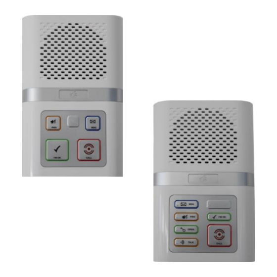
Page 21: Intercom Unit Installation
14. INTERCOM UNIT INSTALLATION There a two types of Advent XT2 intercom; standard with warden call features only, or the door entry type with an additional 2 buttons to answer a call from the door entry panel and release the electric door lock. - Page 22 14. INTERCOM UNIT INSTALLATION The intercom unit should be wall mounted in a central location within each dwelling. Screw fix the intercom rear section securely to the wall using the 4 holes marked “A”. The 2 holes marked “B” can be used for an embedded box. Ensure the case is not twisted as this may prevent the lid fitting or connectors aligning correctly.
-
Page 23: Intercom Unit Dil Switches & Link Settings
PROGRAMMING The total number of intercom units is set in the RS485 Network Setup programming and their ID’s must be set in the Tenants Units Create/Edit programming – see the Advent XT2 Programming Manual (Doc No FM0815). BEEPING INTERCOMS If an intercom “beeps” every 10 seconds, then its ID has been set greater than the number of intercoms set in the system programming. -
Page 24: Intercom Unit Auxiliary Devices
The intercom has the facility to connect ceiling mounted pullcords, smoke detectors, PIR detectors, 4 additional inputs and a hard of hearing strobe light within each dwelling. CEILING PULLCORDS Tynetec Ceiling Pullcord Part No. S00600. Up to 5 pullcords with 24V LED’s can be connected per intercom. No limit if LED’s are NOT connected. - Page 25 PIR detectors should have a normally closed clean contact output which opens when movement is detected. PIR detectors can be powered from the Advent XT2 system network using a 24V-12V Regulator Board (Tynetec P/No. A00557) fitted locally in the intercom.
- Page 26 Advent XT2 Programming Manual (Doc No. FM0815). I/O EXPANDER UNIT Advent XT2 I/O Expander Part No. ZXT925. One I/O Expander can be connected per intercom to provide an additional 6 N/O inputs and 6 changeover relay contact outputs.
- Page 27 SW1 ON & SW2 ON EXTENSION INTERCOM A second Advent XT2 intercom can be connected as an extension to provide audio in another room within the same dwelling. Use a 6 pair CW1308 cable between the master and extension intercoms.
-
Page 28: Fitting & Removing The Intercom
17. FITTING & REMOVING THE INTERCOM Before fitting the intercom front; set the Address and Option Select DIL switches and check links LK1/LK2 are fitted in the correct positions. Ensure all cables are properly terminated and secure spare wires in the clips provided. FITTING THE INTERCOM FRONT Locate the 2 top corners of the intercom front over the 2 top corners of the intercom back, swing downwards and clip together ensuring the pullcord is located in its slots. -
Page 29: Intercom Unit Test Mode
18. INTERCOM UNIT TEST MODE The intercom unit Test Mode allows all input devices to be tested on a per-flat basis without putting an alarm call on the system. Once in Test Mode the intercom will beep as each device is activated, the system log will record each test with the flat number, device type, time and date. -
Page 30: Manager Callpoint Installation
Advent XT2 network. Alternatively, an auxiliary relay output on the Advent XT2 controller can be set to activate with a DTMF character - see the Inputs & Outputs section of the Advent XT2 Programming Manual (Doc No FM0815). Doc No. FM0804 issue 4 Page 30... -
Page 31: Lift Callpoint Installation
The Lift Callpoint must be included in total number of intercom units set in the RS485 Network Setup programming and its ID must be set in the Tenants Units Create/Edit programming – see the Advent XT2 Programming Manual (Doc No FM0815). -
Page 32: Manager's Display Panel Installation
Panel to the Ethernet Switch using local RJ45 wall sockets and standard 2m Patch Leads. Wire between the RJ45 wall sockets as described above. A 5 Port Ethernet Switch (Tynetec P/No. W07485) can be used for up to 4 panels, larger switches are available. - Page 33 PROGRAMMING The total number of Manager’s Display Panels must be set in programming - see the RS485 Network Setup section of the Advent XT2 Programming Manual (Doc No. FM0815). OPTIONAL NOTICE BOARD A large flat screen 1920x1080p HDMI monitor can be connected to the Manager’s Panel HDMI port using a standard Male-Male HDMI cable - max cable length should not exceed 15 metres.
- Page 34 21. MANAGER’S DISPLAY PANEL INSTALLATION On power-up the Manager’s Panel will display the Home screen. Press the Log On button and the Enter Password box will appear as below; Select Engineer from the drop-down list. Enter the default password 2371 then press the keypad Log On button. The System Setup screen will be displayed as below;...
- Page 35 21. MANAGER’S DISPLAY PANEL INSTALLATION From the System Setup screen press the Date Time button; This is used to set the date and time on the local panel. Note: if multiple panels are on the system the panel should be setup by an Engineer to enable the Windows NTP server, allowing all panels to be updated from the Controller.
- Page 36 21. MANAGER’S DISPLAY PANEL INSTALLATION From the System Setup screen press the Panel Settings button; The Visible Tab Pages group of switches allows you to set which Tab Pages are to be visible on the panel. For example, the Flat Status page may not be required on panels in communal areas or it may be that it is visible, but the communal areas should not allow access to the Information Circle (in which case “Allow LED Details Click”...
- Page 37 21. MANAGER’S DISPLAY PANEL INSTALLATION From the System Setup screen press the Change Password button; User (Default Password 1234) – change system operating mode only Manager (Default Password 9876) – access to all user features Engineer (Default Password 2371) – access to all user features and system setup An Engineer can change 3 passwords;...
-
Page 38: Network Receiver Installation
22. NETWORK RECEIVER INSTALLATION Up to 32 x 869MHz Network Receivers (Tynetec P/No. ZXT910) can be installed throughout a site to provide radio coverage for Personal Pendants or other 869MHz Telecare devices. 869MHz SMA Helical Antenna (195mm high) Screw-on Lid... - Page 39 Cable entry should be through the cable gland on the lower face. Network Receivers require a 24V DC power supply and RS485 data connection from the Advent XT2 system network using a 2 pair CW1308 cable. See Tynetec Drg No.
-
Page 40: Door Entry Panel Installation
23. DOOR ENTRY PANEL INSTALLATION The Advent XT2 warden call system can be enhanced to include a door entry facility with the addition of digital door panels and door entry intercoms or door entry telephone handsets. Visitors can call residents direct from the door panels or contact the Manager by pressing the “Manager”... - Page 41 23. DOOR ENTRY PANEL INSTALLATION TERMINATION See Tynetec Drg. No. ZXT900 sheet 4 for detailed wiring connections. Terminal Function Wire Colour Cable DOOR PANEL BOARD white/blue 1 pair 24V DC Supply for Door Panel CW1308 blue/white white/orange 1 pair 0V Supply for Door Panel...
- Page 42 23. DOOR ENTRY PANEL INSTALLATION LOCK CONNECTION The lock release is connected directly to the door panel lock supply (LKSP) and lock return (LKRT) terminals using 1.0mm diameter cable. DOOR PANEL “LKRT” DC LOCK ONLY DOOR PANEL “LKSP” Diode Type: 1N4001 or MOV Type: GNR07D330K IMPORTANT An MOV or reverse bias diode must be fitted directly across all DC lock terminals to prevent back e.m.f.
-
Page 43: Door Entry Telephone Installation
24. DOOR ENTRY TELEPHONE INSTALLATION XT2 door entry telephones (Tynetec P/No. ZXT955) can be connected to a standard intercom within each dwelling. When called, the telephone will ring for a pre-set time or until the handset is lifted. Speech is private between the door entry panel and the dwelling called and cannot be overheard by other users from their handsets or visitors at other door panels. - Page 44 The second handset must have its link LK1 moved to position B (EXTENSION) - it is not possible to have more than 2 telephones per flat. Note: the Advent XT2 controller must be reset for it to detect a second telephone handset has been connected.
-
Page 45: Door Open Alarm Installation
INTERCOM SETTINGS The Advent XT2 intercom which the Door Open Alarm is connected to must have the Options DIL switch 4 set ON and intruder mode must be enabled - see the Advent XT2 Manager’s Panel Manual (Doc No. FM0817). -
Page 46: Line Selector Installation
Wire the Line Selector 12V & EN terminals to the Advent XT2 termination board as shown above. Use a Telecom Lead to connect the Advent XT2 controller PSTN LINE (CON10) to the Line Selector BT LINE socket. Use a Telecom Lead to connect the Telephone Line Master Socket to the Line Selector PRIMARY socket. -
Page 47: Data Repeater Installation
Connect the remaining Advent XT2 network data wires TX+/TX- into the RS485 OUT terminals. LINK SETTINGS LK1-LK4 will normally be fitted in position “A”. Only move if advised by Tynetec’s Technical Support. Link No. Function Link Position “A” Link Position “B”... -
Page 48: Specification - Controller
1.5m x 2183Y white 0.5mm 3 core cable with IEC 90 Free Socket Rechargeable Battery Type 2 x 12V 5Ah Sealed Lead Acid (Tynetec P/No. F00050) Battery Standby Time 12 Hours (based on 5 calls/hour on a typical 40 way system) -
Page 49: Specification - Pa Amplifier
Protection Overload/Over Voltage (auto shut-down/recovery) Mains Input IEC 90 Free Socket Rechargeable Battery Type 1 x 12V 5Ah Sealed Lead Acid (Tynetec P/No. F00050) Battery Standby Time 8 Hours Typical DC-DC Converter Manufacturer/Model No. Ecopac SD-50A-24 (Tynetec P/No. W00590) Input 9.2-18V DC... -
Page 50: Specification - External Battery Box
Safety Approval EN 60950 Features Rechargeable Battery Type 2 x 12V 5Ah Sealed Lead Acid (Tynetec P/No. F00050) Battery Standby Time 12 Hours (based on 5 calls/hour on a typical 40 way system) Battery Leads 1.3m x 24/0.2 PVC insulated wire (BS 4808 Part 2) Crimp Adapter Type 2 Way Tab to Receptacle 4.8mm x 0.8mm (TE Connectivity 63699-1) -
Page 51: Specification - Intercom
31. SPECIFICATION - INTERCOM Tynetec Part No’s ZXT920 Standard, ZXT930 Door Entry, ZXT931 Door Entry & Bluetooth EMC Approval EN 55022 Safety Approval EN 60950 Max No. Intercoms Data Connection RS485 (19200 Baud) Power Requirement 24V DC @ 2mA (standby) -
Page 52: Specification - Intercom I/O Expander
32. SPECIFICATION - INTERCOM I/O EXPANDER Tynetec Part No’s ZXT925 EMC Approval EN 55022 Safety Approval EN 60950 Data Connection RS485 (19200 Baud) Power Requirement 24V DC @ 2mA (standby) 4 Way DIL Switch No Function Features Inputs 6 x Programmable N/O Inputs (switched 0V) -
Page 53: Specification - Manager Callpoint
33. SPECIFICATION - MANAGERS CALLPOINT Tynetec Part No’s ZXT940 Standard, ZXT941 Custom Engraved EMC Approval EN 55022 Safety Approval EN 60950 Data Connection RS485 (19200 Baud) Power Requirement 24V DC @ 2mA (standby) Audio Channels 2 Handsfree Voice Switched with Digital Volume Control... -
Page 54: Specification - Lift Callpoint (Flush Stainless Steel)
34. SPECIFICATION - LIFT CALLPOINT (FLUSH STAINLESS STEEL) Tynetec Part No’s ZXT942 Standard, ZXT943 Custom Engraved EMC Approval EN 55022 Safety Approval EN 60950 Data Connection RS485 (19200 Baud) Power Requirement 24V DC @ 2mA (standby) Audio Channels 2 Handsfree Voice Switched with Digital Volume Control... -
Page 55: Specification - Lift Callpoint (Surface Abs)
35. SPECIFICATION - LIFT CALLPOINT (SURFACE ABS) Tynetec Part No’s ZXT944 EMC Approval EN 55022 Safety Approval EN 60950 Data Connection RS485 (19200 Baud) Power Requirement 24V DC @ 2mA (standby) Audio Channels 2 Handsfree Voice Switched with Digital Volume Control... -
Page 56: Specification - 869Mhz Network Receiver
36. SPECIFICATION - 869MHz NETWORK RECEIVER Tynetec Part No. ZXT910 EMC Approval EN 55022 Safety Approval EN 60950 Radio Approval R&TTE 1999/5/EC Radio Frequency 869.2125MHz Radio Range 75 metres typical (indoor) Max No. TCR’s per Site Data Connection RS485 (19200 Baud) -
Page 57: Specification - Manager's Display Panel
37. SPECIFICATION - MANAGER’S DISPLAY PANEL Manager’s Display Panel Manufacturer/Model No. Avalue Technology Inc. CCD-10W01-7838C-1R Tynetec Part No. ZXT905 EMC Approval FCC Part 15 Class B Digital Device Safety Approval EN 60950-1 Radio Approval R&TTE 1999/5/EC Display Size 10.1” Type... -
Page 58: Specification - Door Entry Panel
38. SPECIFICATION - DOOR ENTRY PANEL Tynetec Part No’s ZXT950 Standard, ZXT951 with Emergency Button (AHA Only) EMC Approval EN 55022 Safety Approval EN 60950 Data Connection RS485 (19200 Baud) Power Requirement 24V DC @ 30mA (standby) Audio Channels 2 Handsfree Voice Switched with Digital Volume Control... -
Page 59: Specification - Door Entry Telephone
39. SPECIFICATION - DOOR ENTRY TELEPHONE Tynetec Part No’s ZXT955 EMC Approval EN 55022 Safety Approval EN 60950 Data Connection RS485 (19200 Baud) Power Requirement 24V DC @ 2mA (standby) Audio Channels 2 Handsfree Voice Switched with Digital Volume Control... -
Page 60: Specification - Line Selector
40. SPECIFICATION - LINE SELECTOR Tynetec Part No. ZXT330 EMC Approval Safety Approval Features Power Requirement 12V DC @ 40mA active (0mA standby) BT47 Relay Fully sealed DPDT contacts rated 2A @ 30V DC Telecom Connectors 3 x BT Type 431A Sockets Screw Terminals 12V &... -
Page 61: Specification - Door Open Alarm
42. SPECIFICATION - DOOR OPEN ALARM Tynetec Part No. ZDA025 EMC Approval Safety Approval Features Power Requirement 24V DC @ 50mA (standby) Links LK1&LK2 Cut LK1 and fit LK2 for 12V DC supply Link LK3 Cut to isolate Piezo sounder... -
Page 62: Specification - Master Strobe
43. SPECIFICATION - MASTER STROBE Tynetec Part No. ZSL060 (Blue) & ZSL065 (Clear) EMC Approval Safety Approval Features Power Requirement 24V DC @ 2mA (standby) 90mA active Data Connection RS485 (19200 Baud) Max No. Strobes 4 per combined intercom (2 warden call + 2 door entry) -
Page 63: Amendments Record
45. AMENDMENTS RECORD The table below lists significant changes to this manual; Issue Amendments Date Preliminary issue 16/08/18 Manager’s Panel setup details added 27/09/18 NTR Antenna changed, Currents added, Ext Battery Box added 21/02/19 Strobes updated (pages 27, 43 & 62) 13/05/19 Doc No.
Need help?
Do you have a question about the Advent XT2 and is the answer not in the manual?
Questions and answers