Veeder-Root TLS-350 System Setup Manual
Hide thumbs
Also See for TLS-350:
- User manual ,
- Troubleshooting manual (56 pages) ,
- Installation manual (45 pages)
Table of Contents
Advertisement
Quick Links
Download this manual
See also:
Installation Manual
Advertisement
Table of Contents

Related Manuals for Veeder-Root TLS-350


Summary of Contents for Veeder-Root TLS-350
- Page 1 • Manual No: 576013-623 Revision: AM Software Version X33 TLS-3XX Series Consoles System Setup Manual...
- Page 2 Customer Service will work with production facility to have the replacement product shipped as soon as possible. If “lost” equipment is delivered at a later date and is not needed, Veeder-Root will allow a Return to Stock without a restocking fee.
-
Page 3: Table Of Contents
Arrangement of Keys .....................2-1 Operating Keys......................2-1 Alphanumeric Keys....................2-1 Blue Key (Maintenance Tracker - TLS-350 Only)..........2-2 White Key (Maintenance Report - TLS-350 Only) ..........2-2 Using the Operating Keys ....................2-2 Using the Alphanumeric Keys ..................2-3 Entering Alphanumeric Data..................2-4 Special Characters and Cursor Movement............2-4 3 Setup Mode Organization Functions ........................3-1... - Page 4 BDIM Trans Alarm Delay .....................5-17 System Security Code ....................5-17 Maintenance History ....................5-18 Tank Chart Security .....................5-18 Custom Alarm Labels ....................5-19 Service Notice (TLS-350 Consoles Only) ..............5-27 Inventory Alarms Threshold Units ................5-28 System Beeper ......................5-29 Mass/Density .......................5-30 Fiscal Height Security ....................5-30 Alarm Reduction ......................5-31...
- Page 5 Table of Contents Answer On......................6-3 Security Code ......................6-3 Setting the Modem Type (international Installations) ..........6-4 Modem Setup String....................6-4 Dial Tone Interval ....................6-4 DTR Normal State ....................6-4 Specifying Port Settings for Additional Communication Modules......6-5 Continue Communications Setup ................6-5 Auto-Transmit Setup (RS-232 or RS-232/RS-485 Modules Only) .........6-5 Auto-Transmit Method ...................6-5 Auto Delay Time ....................6-6 Auto Repeat Time....................6-6...
- Page 6 Table of Contents Setting Up Auto-Dial Alarms for Additional Destinations ........6-20 RS-232 End of Message ....................6-20 7 In-Tank Setup Selecting the In-Tank Setup Function ................7-1 Tank Configuration ......................7-1 How the System Configures In-Tank Probes ............7-1 Specifying In-Tank Probe Positions...............7-1 Product Labels .......................7-2 Product Code .........................7-2 Coefficient of Thermal Expansion ..................7-3 Tank Density ........................7-4...
- Page 7 Table of Contents Stick Offset (International Option) ................7-24 HRM Reconciliation Warning Limit (International Option) ..........7-25 HRM Reconciliation Alarm Limit (international Option) ..........7-25 Delivery Report Delay Time ..................7-26 Pump Threshold ......................7-26 Setting Up Additional Tanks ..................7-26 8 In-Tank Leak Tests Selecting the In-Tank Leak Test Setup Function ............8-1 Leak Test Method: All Tank/Single Tank ...............8-1 Leak Test Frequency .....................8-2 Test On Date ......................8-2...
- Page 8 Table of Contents Pressure Offset ......................10-9 Venting The Line ....................10-9 Determining a Pressure Offset Value for each Transducer.......10-10 Entering the Pressure Offset Value for each Transducer........10-10 Mechanical Blenders ....................10-11 Setting Up Additional PLLDs ..................10-11 11 Wireless Pressurized Line Leak Detection Line Manifolding Implications for AccuChart ..............11-1 WPLLD Setup ......................11-1 Activating WPLLDs ......................11-1...
- Page 9 Table of Contents 14 Line Leak Test Lockout Selecting the Line Leak Test Lockout Function ............14-1 Lockout Schedule ......................14-1 Daily Schedule ......................14-1 Individual Schedules ....................14-2 Entering Additional Test Lockout Schedules ...............14-3 15 Pump Sense Setup Selecting the Pump Sense Function ................15-1 Pump Sense Configuration ..................15-1 How the System Configures Pump Sense Modules..........15-1 Specifying Pump Sense Positions...............15-1...
- Page 10 Table of Contents Before You Begin ....................19-2 Specifying Vapor Threshold Levels ..............19-3 Vapor Sensor Category ....................19-3 Setting Up Additional Vapor Sensors ................19-4 20 Groundwater Sensor Setup Selecting the Groundwater Sensor Setup Function .............20-1 Groundwater Sensor Configuration ................20-1 How the System Configures Groundwater Sensors ..........20-1 Specifying Groundwater Sensor Positions ............20-1 Groundwater Sensor Location ..................20-2 Groundwater Sensor Category ..................20-2...
- Page 11 Table of Contents Relay Designation ......................24-2 Selecting Relay Type ....................24-2 Assignment Method .....................24-3 In-Tank Alarms ....................24-3 Remaining Alarm Groups ..................24-5 Liquid Sensor Alarms ..................24-5 Vapor Sensor Alarms ..................24-5 External Inputs Alarms ..................24-5 Line Leak Alarms (VLLD) ..................24-5 Groundwater Sensor Alarms ................24-5 2 Wire C.L.
- Page 12 System Setup ....................... B-1 Comm Board (1, 2, etc.) Setup ..................B-2 In-Tank Setup ....................... B-2 Leak Test Method Setup ....................B-3 Appendix C: Setup Parameters for TLS-350 System - International Figures Figure 4-1. Battery Backup Switch and DIP Switch Location - TLS-300 Console ....................4-3...
-
Page 13: Introduction
Contractor Certification Requirements Veeder-Root requires the following minimum training certifications for contractors who will install and setup the equipment discussed in this manual: Installer Certification (Level 1): Contractors holding valid Installer Certification are approved to perform wiring and conduit routing;... -
Page 14: Safety Precautions
Introduction Safety Precautions Safety Precautions The following safety symbols may be used in this manual to alert you to important safety hazards and precautions. EXPLOSIVE FLAMMABLE Fuels and their vapors are extremely Fuels and their vapors are extremely explosive if ignited. flammable. -
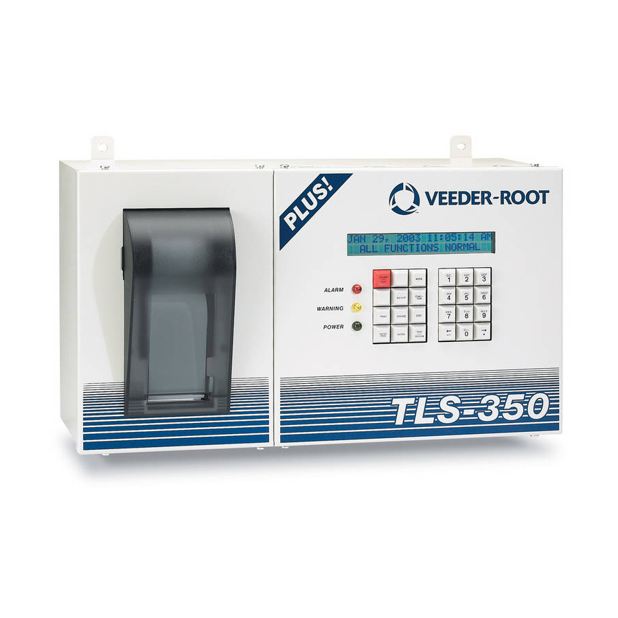
Page 15: Front Panel Keypads
Front Panel Keypads You use the front panel keypads to enter information into the system. Arrangement of Keys The keypads (see Figure 2-1) consist of two groups of 12 keys. The functions for each key have been established to make movement within the setup mode, entry of setup data, and selection of setup choices as simple as possible consoles\keypad.eps ALARM... -
Page 16: Blue Key (Maintenance Tracker - Tls-350 Only)
(See “Using the Alphanumeric Keys” on page 2-3). BLUE KEY (MAINTENANCE TRACKER - TLS-350 ONLY) Contractor plugs a valid ID Key into the TLS and presses the blue key to log in for a work session. Note: This key is available in consoles with Version 27 and higher software. -
Page 17: Using The Alphanumeric Keys
Front Panel Keypads Using the Alphanumeric Keys TANK/SENSOR The TANK/SENSOR key is used to advance by tank or sensor through setup procedures or dis- TANK played data. SENSOR CHANGE CHANGE is used in Normal and Setup modes to enter data, revise existing data or change an CHANGE entry. -
Page 18: Entering Alphanumeric Data
Front Panel Keypads Using the Alphanumeric Keys ENTERING ALPHANUMERIC DATA Keys 0 through 9 provide both alphabetic and numeric capability by activating each character shown on the key with successive pushes of the key. Table 2-1 shows characters assigned to each of the numeric keys for all languages except Japanese, Russian, Turkish, and Greek. - Page 19 Front Panel Keypads Using the Alphanumeric Keys The Right-Arrow key lets you advance the cursor to the right when making alphanumeric entries such as station headers and when selecting certain parameters such as module configurations. The step-by-step setup instructions will identify when this function should be used. The . (decimal) is used in numeric entries as required.
-
Page 20: Setup Mode Organization
Setup Mode Organization The Setup Mode is used to enter information and operating parameters that govern the way your system monitors your installation. Setup data is entered via the front panel keypads. The previous section describes in detail the functions of each key. Functions Functions are the major groups in the Setup Mode of the console. - Page 21 Setup Mode Organization Setup Mode Programming Table a setup report for record keeping purposes after completing your system’s setup. In the System Setup Table below, STEP refers to pressing that key on the front panel. FUNCTION Setup Mode Table ...
- Page 22 Setup Mode Organization Setup Mode Programming Table STEP 0.2 gph (0.76 lph) Line Test Auto-Confirm (Enable/Disable) STEP 0.1 gph (0.38 lph) Line Test Auto-Confirm (Enable/Disable) STEP Daylight Savings Time (Disable/Enable) STEP HRM-QPLD Printouts (Enable/Disable) STEP Re-direct Local PrintouT (Enable/Disable) STEP Euro Protocol Prefix STEP Bdim Trans Alarm Delay...
- Page 23 Setup Mode Organization Setup Mode Programming Table STEP Overfill Limit STEP High Product STEP Delivery Limit STEP Low Product STEP Leak Alarm Unit STEP Sudden Loss Limit STEP Tank Tilt STEP Probe Offset STEP Siphon Manifolded STEP Line Manifolded STEP Leak Minimum Periodic STEP Leak Minimum Annual...
- Page 24 Setup Mode Organization Setup Mode Programming Table STEP User Defined Pipe Type - If selected in Piping Type (1st Line Length/2nd Line Length - if neces- sary/1st Bulk Modulus/2nd Bulk Modulus- if necessary/Thermal Coeff.) STEP Thermal Coefficient - If certain piping types selected STEP 0.2 gph (0.76 lph) Line Leak Test Scheduling (Disabled/Repetitive/Monthly/Manual) STEP...
- Page 25 Setup Mode Organization Setup Mode Programming Table FUNCTION LINE LEAK LOCKOUT SETUP STEP Lockout Schedule (Daily [Start Time/Stop Time]/ Individual [Start Day/Time/Stop Day/Time]) FUNCTION PUMP SENSOR SETUP STEP Pump Sense Config. Module 1 ( up to 8) STEP Select Tank STEP Dispense Mode FUNCTION...
- Page 26 Setup Mode Organization Setup Mode Programming Table STEP Sensor Location STEP Category (Annular Space/Dispenser Pan/Monitor Well/STP Sump/Piping Sump/Other) FUNCTION 2-WIRE CL SENSOR SETUP STEP Sensor Config. - Module 1 (up to 8) STEP Sensor Location STEP Sensor Types (Discrim. Interstitial/Ultra 2) STEP Category (Annular Space/Dispenser Pan/Monitor Well/STP Sump/Piping Sump/Other) FUNCTION...
- Page 27 Setup Mode Organization Setup Mode Programming Table FUNCTION LINE DISABLE SETUP (VLLD) STEP Relay Assignments - for each relay except Pump Comm Control types (In-Tank Alarms [None/ All /Single]/ Liquid Sensor Alarms [None/All /Single]/ Vapor Sensor Alarms [None/All /Single]]/ External Inputs [None/All /Single]]/ Groundwater Alarms [None/All /Single]/ 2-Wire CL (Type A) Alarms [None/All /Single]/ 3-Wire CL (Type B) Alarms [None/All /Single]/ Power Side DIM Alarms [None/All /Single]/ Reconciliation Alarms [None/All /Single]/ PLLD Alarms [None/All / Single]/ WPLLD Alarms [None/All /Single]/ Comm Side DIM Alarms [None/All /Single]/ Pump...
-
Page 28: Prior To Applying Ac Power To The Console
If you want to disable the security code feature and allow front panel and RS-232 system setup access, make sure that switches #3 and #4 on DIP switch S2 are both in the OPEN position. TLS-350 CONSOLES If you want to disable the security code feature and allow front panel and RS-232 system setup access, make sure that switches #1 and #2 on DIP switch SW2 are both in the OPEN position. - Page 29 Prior to Applying AC Power to the Console Security Code Enable/Disable consoles\keypad.eps ALARM MODE TEST FUNCT- BACKUP TION PRINT CHANGE STEP PAPER TANK ENTER FEED SENSOR Legend for numbered boxes: 1. Maintenance Report (white) key 3. Alphanumeric keypad 2. Maintenance Tracker (blue) key 4.
-
Page 30: Figure 4-1. Battery Backup Switch And Dip Switch Location - Tls-300 Console
Prior to Applying AC Power to the Console Security Code Enable/Disable consoles\300dp1.eps Legend for numbered boxes: 1. Battery Backup Switch (S1) shown in OFF position 5. DIP switch 1 can be in either position - It is shown in closed position (open side up, number side down) 2. -
Page 31: Figure 4-2. Battery Backup Switch And Dip Switch Location Tls-350 Consoles With Cpu Board
3. Battery Backup Switch (S1) - Shown in ON position 7. RS-232 Security Code (DIP Switch 2) (up) 4. DIP switches: 1 - 4 shown in the OPEN position (open end down, number end up) Figure 4-2. Battery Backup Switch and DIP Switch Location TLS-350 Consoles with CPU Board... -
Page 32: Figure 4-3. Battery Backup Switch And Dip Switch Location Tls-350 Consoles With Ecpu Board
6. Battery Backup Switch (SW1)- Shown in OFF position (down) 3. RS-232 Security Code (DIP Switch 2) 7. DIP Switch 4 (not used) 4. Front Panel Security Code (DIP Switch 1) Figure 4-3. Battery Backup Switch and DIP Switch Location TLS-350 Consoles with ECPU Board... -
Page 33: Battery Backup
2. The console front panel display will cycle through the following screens: (NOTE: if you enabled the HRM feature (see “TLS-350 Consoles” on page 4-1), the system date/time format will default to DD-MM-YY HH:MM:SS). CLEARING ALL RAM... - Page 34 Prior to Applying AC Power to the Console Applying AC Power to the Console and the front panel display will read: MMM DD, YYYY HH:MM:SS XM BATTERY IS OFF 3. Press the ALARM/TEST key to silence the audible alarm. Slide the Battery Backup switch (S1 or SW1) to the ON position.
-
Page 35: System Setup
System Setup Programming Guidelines This manual details setup procedures for every available console Function within the Setup Mode. The manual is divided into sections for each Function as they appear on the display, beginning with Section 5, System Setup through Section 26, Archive Utility. Depending on your console type and its installed features, you may only see (and be able to program) some of the Functions and/or Steps. -
Page 36: Selecting The System Setup Function
System Setup Selecting the System Setup Function To print a Setup Data Report, press the MODE key to display the Setup Mode main screen (see below), then press the PRINT key. SETUP MODE PRESS <FUNCTION> TO CONT Selecting the System Setup Function Press MODE to select the Setup Mode, then press FUNCTION until you see the message: SYSTEM SETUP PRESS <STEP>... -
Page 37: Setting The Date And Time Format
You can set the system units to U.S. units (gallons, gal/hour, inches, F), metric units (litres, litres/hour, millimeters, C), or imperial gallons (imperial gallons, imp. gal/hour, inches, F). If the HRM feature was enabled (see “TLS-350 Consoles” on page 4-1), the default units will be metric. -
Page 38: Current Time
System Setup Current Time Current Time If necessary, press STEP until you see the message: SET TIME TIME: XX:XX AM PM To accept the time shown, press STEP. (The system displays the ENTER STATION HEADER message.) To set a different time, press CHANGE and enter the correct time from 12:00 to 11:59 then am or pm. (Press the Left or Right Arrow to select AM or PM). -
Page 39: Shift Bir Printouts
System Setup Shift BIR Printouts To leave a shift start time disabled, press STEP. (The system displays the SHIFT START TIME message for the next shift.) To set a start time for shift 1, press CHANGE, and enter the shift 1 start time. Press the Left or Right Arrow to select AM or PM. -
Page 40: Tc Ticketed Delivery
System Setup TC Ticketed Delivery TC Ticketed Delivery If necessary, press STEP until you see the message: TC TICKETED DELIVERY DISABLED If you enabled ticketed delivery, you can choose whether the values you enter are standard (gross) volumes or temperature-compensated (TC) volumes (see page 5-13 for a description of “Temperature Compensation Value”). For standard volumes, press STEP to leave TC Ticketed Delivery disabled. -
Page 41: Periodic Delivery Variance Reports
System Setup Variance Reports To enable Weekly Delivery Variance Reports, press CHANGE, ENTER, then STEP. PERIODIC DELIVERY VARIANCE REPORTS If necessary, press STEP until you see the message: PERIODIC DLVY VAR RPTS DISABLED To enable Periodic Delivery Variance Reports, press CHANGE, ENTER, then STEP. DAILY BOOK VARIANCE REPORTS If necessary, press STEP until you see the message: DAILY BOOK VAR RPTS... -
Page 42: Periodic Variance Analysis Reports
System Setup Tank Periodic Test Needed Warnings To enable Weekly Variance Analysis Reports, press CHANGE, ENTER, then STEP. PERIODIC VARIANCE ANALYSIS REPORTS If necessary, press STEP until you see the message: PERIODIC VAR ANALY RPTS DISABLED To enable Periodic Variance Analysis Reports, press CHANGE, ENTER, then STEP. Tank Periodic Test Needed Warnings If necessary, press STEP until you see the message: TANK PER TST NEEDED WRN... -
Page 43: Disable Tank Periodic Test Needed Warnings
System Setup Tank Annual Test Needed Warnings DISABLE TANK PERIODIC TEST NEEDED WARNINGS To disable Tank Periodic Test Needed Warnings, press CHANGE in response to the Tank Annual Test Needed Warnings Enabled message. The system now displays: TANK PER TST NEEDED WRN DISABLED Press ENTER. -
Page 44: Disable Tank Annual Test Needed Warnings And Alarms
System Setup Line Re-Enable Method Press STEP. The system displays the message: TANK ANN TST NEEDED ALM DAYS = XXX The default value is 355 days. If you do not want to accept the default, press CHANGE. Enter the number of days after which you want the system to alarm if a test has not been passed (0 to 365). -
Page 45: Enable Line Periodic Test Needed Warnings And Alarms
System Setup Line Annual Test Needed Warnings or conducted in a specified number of days (0 to 30), and activate an alarm if a test has not been passed after a warning, or a specified number of days. ENABLE LINE PERIODIC TEST NEEDED WARNINGS AND ALARMS To enable Line Periodic Test Needed Warnings, press CHANGE, ENTER, then STEP. -
Page 46: Enable Line Annual Test Needed Warnings And Alarms
System Setup Line Annual Test Needed Warnings The system monitors the amount of time since the last passed 0.1 gph (0.38 lph) line test. By enabling Line Annual Test Needed Warnings, you can have the system provide a warning when a 0.1 gph line test has not been passed, or conducted in a specified number of days (0 to 365), and activate an alarm if a test has not been passed after a warning, or a specified number of days. -
Page 47: Remote Printer Page Eject
System Setup Remote Printer Page Eject Remote Printer Page Eject If necessary, press STEP until you see the message: REMOTE PRINTER PAGE EJECT NOTE: This system feature is for systems equipped with a Remote Printer Interface Module and Remote Printer only. -
Page 48: Tanker Load Report - International Option
System Setup Tanker Load Report - International Option To enter a different TC reference temperature, press CHANGE. Enter a value between 0 and 120°F (-17 to +49°C). Press ENTER to confirm your entry. The system displays: VALUE (DEG F): +(TC Value) PRESS <STEP>... -
Page 49: Precision Test Duration (Plld/Wplld Only)
System Setup Precision Test Duration (PLLD/WPLLD Only) Press STEP to display the message: H-PROTOCOL DATA FORMAT HEIGHT This option allows either Tank Height or Tank Volume data for H-protocol. On power up, this feature will default to HEIGHT for backward compatibility. Press CHANGE, then ENTER to change the default. Accept the default if you are not using H-protocol. -
Page 50: Daylight Savings Time
System Setup Daylight Savings Time Daylight Savings Time This feature allows you to enter Daylight Savings Start and End Dates/Times. Once enabled, the console will automatically adjust for daylight savings time on the dates and times you enter here. Press STEP to display the message: DAYLIGHT SAVINGS TIME DISABLED To leave Daylight Savings Time disabled, press STEP. -
Page 51: Qpld Monthly Printout - International Option
QPLD Monthly Printout - International Option When the HRM feature is enabled (see “TLS-350 Consoles” on page 4-1), QPLD is automatically enabled and it will print out a report once a month. If this report is not required it may be disabled as follows. -
Page 52: Maintenance History
ENTER. The system confirms your entry with the message: CODE: XXXXXX PRESS <STEP> TO CONT Maintenance History The Maintenance Report feature is available in the TLS-350 with version 27 software and a NVMEM 203 card installed. Press STEP to display the message: MAINTENANCE HISTORY... -
Page 53: Custom Alarm Labels
System Setup Custom Alarm Labels Press ENTER to continue: TANK CHART SECURITY This display appears if a passcode has not been entered (default). All zeros CODE : 000000 disables Tank Chart Security. This display appears if Tank Chart Security is enabled - a passcode other than all zeros TANK CHART SECURITY has been entered. - Page 54 System Setup Custom Alarm Labels • LED: Turn on the front panel Warning or write in your new label in the Custom Alarm Label column of Table 5-1. When you have completed your custom alarm label entries, press the PRINT key while in System Setup, to print out a copy of your changes.
-
Page 55: Table 5-1. Alarm Labels
System Setup Custom Alarm Labels Note: The ID Code column of Table 5-1 contains codes that enable service technicians to recognize your custom labels. Table 5-1. Alarm Labels ID Code Alarm Category Display/print Alarm Label Custom Alarm Label Type/Num Autodial Alarm Label System Alarm PAPER OUT 01/01... - Page 56 System Setup Custom Alarm Labels Table 5-1. Alarm Labels ID Code Alarm Category Display/print Alarm Label Custom Alarm Label Type/Num Autodial Alarm Label Tank Alarm SETUP DATA WARNING 02/01 LEAK ALARM 02/02 LEAK HIGH WATER ALARM 02/03 HIGH WATER OVERFILL ALARM 02/04 OVERFILL LOW PRODUCT ALARM...
- Page 57 System Setup Custom Alarm Labels Table 5-1. Alarm Labels ID Code Alarm Category Display/print Alarm Label Custom Alarm Label Type/Num Autodial Alarm Label Liquid Sensor SETUP DATA WARNING (for type, (03), Vapor Sen- see alarm sor (04), Ground- category)/ water Sensor (07), Type A Sen- sor (08), Type B FUEL ALARM...
- Page 58 System Setup Custom Alarm Labels Table 5-1. Alarm Labels ID Code Alarm Category Display/print Alarm Label Custom Alarm Label Type/Num Autodial Alarm Label VLLD Alarm PER-PUMP TEST FAIL 06/17 PER PUMP PER-PUMP SELF FAIL 06/18 PER PSELF ANN-LINE TEST FAIL 06/19 ANN LINE ANN-LINE SELF FAIL...
- Page 59 System Setup Custom Alarm Labels Table 5-1. Alarm Labels ID Code Alarm Category Display/print Alarm Label Custom Alarm Label Type/Num Autodial Alarm Label PLLD Alarm PLLD OPEN ALARM 21/06 OPEN ALARM PLLD SHUTDOWN ALARM 21/08 SHUTDOWN PERIOD LINE FAIL 21/11 PERIOD FAIL ANN TST NEEDED WRN 21/12...
- Page 60 System Setup Custom Alarm Labels Table 5-1. Alarm Labels ID Code Alarm Category Display/print Alarm Label Custom Alarm Label Type/Num Autodial Alarm Label Smart Sensor SETUP DATA WARNING 28/01 SETUP WARN Alarm COMMUNICATION ALARM 28/01 COMM ALARM SENSOR FAULT ALARM 28/03 SENSR FAULT FUEL WARNING...
-
Page 61: Service Notice (Tls-350 Consoles Only)
System Setup Service Notice (TLS-350 Consoles Only) Service Notice (TLS-350 Consoles Only) When service is preformed at a site, “false” alarms and “false” deliveries can be generated. “False” alarms can trigger unneeded service dispatches to the site and “false” deliveries can cause reconciliation problems. -
Page 62: Inventory Alarms Threshold Units
System Setup Inventory Alarms Threshold Units Press CHANGE: SERVICE NOTICE ENABLED Press ENTER: ENABLED PRESS <STEP> TO CONTINUE Press STEP: DELIVERY OVERRIDE Menu will only appear if Service Notice is enabled and there is a probe module DISABLED If Delivery Override is desired, press CHANGE, otherwise, press STEP. DELIVERY OVERRIDE ENABLED Press ENTER:... -
Page 63: System Beeper
System Setup System Beeper The Inventory Alarms and selectable threshold configurations are listed in Table 5-2 below: Table 5-2. Configurations For Setting Inventory Alarm Thresholds Threshold Configuration Inventory Alarm Standard All %Full All Volume All Height Custom Max or Label Volume %Full Volume... -
Page 64: Mass/Density
System Setup Mass/Density Press STEP: DISABLED ARE YOU SURE? : NO Press CHANGE: DISABLED ARE YOU SURE? : YES Press ENTER: ARE YOU SURE? : YES PRESS <STEP> TO CONTINUE Mass/Density If necessary, press STEP until you see the message: MASS/DENSITY PRESS <ENTER>... -
Page 65: Alarm Reduction
Height Security parameter AND the following tank height modifying parameters Probe Offset, Tank Tilt and Float Size cannot be modified! NOTE: If the TLS-350 is physically sealed then the Fiscal Height Security menu is displayed but cannot be changed. Press ENTER:... -
Page 66: Communications Setup
Communications Setup The Communications Setup function allows you to: enter communication port settings for each Comm Module; enter dates/times for each of the Comm Modules to automatically dial out and connect to a selected remote device; and select the alarm notifications and status reports (modem modules only) for transmission to the remote device once the connection has been made. -
Page 67: Parity
Communications Setup Port Settings The system labels the communications module in the leftmost slot as “COMM BOARD: 1”. To access port settings for the remaining communications modules, press TANK/SENSOR. Choose the baud rate that matches the external device connected to the module. For the RS-232 and Dual-Port RS-232/RS-485 Modules, the choices are;... -
Page 68: Dial Type
Communications Setup Port Settings The choices are 7 or 8. To accept 7, press STEP. To choose 8, press CHANGE and press ENTER. The system confirms your choice with the message: DATA LENGTH: X DATA PRESS <STEP> TO CONTINUE Press STEP to continue. DIAL TYPE Choose the Dial Type (Tone or Pulse) that matches the receiving device. -
Page 69: Setting The Modem Type (International Installations)
Communications Setup Port Settings Press STEP to continue. SETTING THE MODEM TYPE (INTERNATIONAL INSTALLATIONS) This feature lets you select the modem used with a SiteLink Module. COMM BOARD: 1 (S-Link) MODEM: NETCOMM SMART M7F Press ENTER to accept the modem option or press CHANGE and then ENTER to choose US ROBOTICS (UK), VR TLS ANALOG MOD, or VR TLS GSM MODEM. -
Page 70: Specifying Port Settings For Additional Communication Modules
Communications Setup Auto-Transmit Setup (RS-232 or RS-232/RS-485 Modules Only) This feature allows the user to program the S-Sat Module’s Data Transmit Ready (DTR) normal state to either High or Low. The default state is High. Press CHANGE and ENTER to select the Low state, or press STEP to accept the default state and continue. -
Page 71: Auto Delay Time: 005
Communications Setup Auto-Transmit Setup (RS-232 or RS-232/RS-485 Modules Only) • AUTO HIGH WATER LIMIT • AUTO OVERFILL LIMIT • AUTO LOW PRODUCT • AUTO THEFT LIMIT • AUTO DELIVERY START • AUTO DELIVERY END • AUTO EXTERNAL INPUT ON • AUTO EXTERNAL INPUT OFF •... -
Page 72: Phone Directory Setup
Communications Setup Phone Directory Setup Phone Directory Setup If necessary, press STEP until you see the message: PHONE DIRECTORY SETUP PRESS <ENTER> NOTE: This message appears only for systems equipped with a modem module. Through the Phone Directory feature, you can program up to 8 telephone numbers for automatic dialing to teletype, facsimile, or computer modems. -
Page 73: Select Modem
Communications Setup Phone Directory Setup number for the selected receiver, press CHANGE. Enter the number and press ENTER to confirm your entry. The system displays: D1: (Phone #) PRESS <STEP> TO CONTINUE Press STEP to continue. SELECT MODEM After you set the receiver phone number, the system displays the message: SELECT MODEM: 3 Your system may have up to three a modem modules in slots 1, 2, and/or 3 of the Comm Bay. -
Page 74: Retry Delay Time
Communications Setup Phone Directory Setup You can specify the number of times the system attempts to redial a telephone number if there is a busy signal, no answer, or incomplete connection. To enter the number, press CHANGE and enter a number between 3 and 99. Press ENTER to confirm your entry. -
Page 75: Auto-Dial Setup
Communications Setup Auto-Dial Setup Auto-Dial Setup If necessary, press STEP until you see the message: AUTO DIAL SETUP PRESS <ENTER> NOTE: This message appears only if you have a modem module installed and after you complete the Phone Directory Setup. Using Auto-Dial Setup, you can tell the system what reports to transmit, to whom to transmit, and when to transmit. -
Page 76: Auto Dial Method: All Phones/Single Phone
Communications Setup Auto-Dial Setup Press TANK/SENSOR to select a second receiver and repeat the steps described above to select the types of reports to be transmitted to that receiver. Press TANK/SENSOR to select a third receiver, and so forth. When you have selected reports to transmit to all the receivers that you want, press STEP in response to the RCVR REPORT LIST message. -
Page 77: Auto-Dial Frequency: Annually
Communications Setup Auto-Dial Setup To set the Auto-Dial Frequency to On Date, press STEP. (To set the frequency to Annually, Monthly, Weekly, Daily, or BIR End follow the procedures described in the corresponding section below.) The system displays the message: DIAL ON DATE: ALL RCVRS DATE: XX/XX/XXXX Press CHANGE, and enter the date on which you want the reports to be transmitted. -
Page 78: Auto-Dial Frequency: Monthly
Communications Setup Auto-Dial Setup For example, if you chose to transmit the reports on the Friday of the first week of June, the system would display the message: JUNE WEEK 1 FRI PRESS <STEP> TO CONTINUE Press STEP to continue. If you are using the All Phones method or have set up all the receivers for Single Phone, refer to the section entitled “Continue Communications Setup”... -
Page 79: Auto-Dial Frequency: Daily
Communications Setup Auto-Dial Setup To set the date of the weekly transmission, press CHANGE until the day on which you want to transmit the reports appears. Press ENTER to confirm the date: PRESS <STEP> TO CONTINUE Press STEP to continue. If you are using the All Phones method or have set up all the receivers for Single Phone, refer to the section entitled “Continue Communications Setup”... -
Page 80: Setting Up The Frequency For Additional Receivers (Single Phone Only)
Communications Setup Auto-Dial Alarm Setup To enable this feature, press CHANGE: DIAL BIR END: ALL RCVRS TIME: AUTO DAILY CLOSING Press ENTER and the system confirms your choice with the message: TIME: AUTO DAILY CLOSING PRESS <STEP> TO CONTINUE Press STEP to continue. If you are using the All Phones method or have set up all the receivers for Single Phone, refer to the section entitled “Continue Communications Setup”... -
Page 81: In-Tank Alarms
Communications Setup Auto-Dial Alarm Setup Through the Auto Dial Alarm Setup, you can tell the system to send reports of alarm conditions to the programmed destinations. Choose No, if you do not wish to send a report for a particular alarm condition, or Yes if you do want the alarm reported. -
Page 82: Remaining Alarm Groups
Communications Setup Auto-Dial Alarm Setup REMAINING ALARM GROUPS Continue to step through all of the available alarm groups, selecting the various alarms from the groups that you want to send to the selected destination (D1, D2, etc.). The procedure for bypassing or selecting alarms from each group and then assigning them to a device in that group is the same as discussed for In-Tank alarms above. -
Page 83: Wire C.l. Sensor Alarms
Communications Setup Auto-Dial Alarm Setup 2 WIRE C.L. SENSOR ALARMS If necessary, press STEP until you see the message: D1: (Destination) 2 WIRE CL ALARMS: NO Select the 2 Wire C.L. Sensor Alarms to send (ref. Alarm List in Table 6-2). 3 WIRE C.L. -
Page 84: Wireless Pressure Line Leak Detector (Wplld) Alarms
Communications Setup Auto-Dial Alarm Setup WIRELESS PRESSURE LINE LEAK DETECTOR (WPLLD) ALARMS If necessary, press STEP until you see the message: D1: (Destination) WPLLD LINE LEAK: NO Select the WPLLD Line Leak Alarms to send (ref. Alarm List in Table 6-2). COMMUNICATION SIDE DIM ALARMS If necessary, press STEP until you see the message: D1: (Destination) -
Page 85: Setting Up Auto-Dial Alarms For Additional Destinations
Communications Setup RS-232 End of Message SETTING UP AUTO-DIAL ALARMS FOR ADDITIONAL DESTINATIONS If necessary, press STEP until you see the message: AUTO DIAL ALARM SETUP PRESS <ENTER> If you have additional destinations to which to send alarms, press ENTER. The system displays the message: D1: (Destination) IN-TANK ALARMS: NO Press TANK/SENSOR to select another destination (D1, D2, etc.). -
Page 86: Table 6-2. Alarm List
Communications Setup RS-232 End of Message Table 6-2. Alarm List In-Tank Alarms LEAK HIGH WATER OVERFILL NOTE: A strikethrough an alarm condition means that LOW PRODUCT you will see the condition in SUDDEN LOSS the sequence. HI PRODUCT INVALID HGT PROBE OUT WATER WARN DLVY NEEDED... - Page 87 Communications Setup RS-232 End of Message Table 6-2. Alarm List Liquid Sensor Alarms FUEL OPEN SHORT WATER WATER OUT HIGH LIQUID LOW LIQUID LIQ WARNING Vapor Sensor Alarms FUEL OPEN SHORT WATER WATER OUT HIGH LIQUID LOW LIQUID LIQ WARNING External Inputs Alarm CLOSED Sensor Out alarm...
- Page 88 Communications Setup RS-232 End of Message Table 6-2. Alarm List VLLD Alarms SHUTDOWN SELF WARN HANDLE WARN GROSS LINE GROSS LSELF GROSS PUMP GROSS PSELF PER NEED WN ANN NEED WN PER NEED AL ANN NEED AL PER LINE PER LSELF PER PUMP PER PSELF ANN LINE...
- Page 89 Communications Setup RS-232 End of Message Table 6-2. Alarm List 2-Wire C.L. Sensor Alarms FUEL OPEN SHORT WATER WATER OUT HIGH LIQUID LOW LIQUID LIQ WARNING 3-Wire C.L. Sensor Alarms FUEL OPEN SHORT WATER WATER OUT HIGH LIQUID LOW LIQUID LIQ WARNING Receiver Alarms SERVICE REPORT WARN...
- Page 90 Communications Setup RS-232 End of Message Table 6-2. Alarm List PLLD Alarms GROSS FAIL GRS NEED AL ANN LN FAIL PER NEED WN PER NEED AL OPEN ALARM SHUTDOWN PERIOD FAIL ANN NEED WN ANN NEED AL LO PRES ALM HANDLE ALRM FUEL OUT LN EQ FAULT...
- Page 91 Communications Setup RS-232 End of Message Table 6-2. Alarm List Smart Sensor Alarms SETUP WARN COMM ALARM SENSR FAULT FUEL WARN FUEL ALARM WATER WARN Smart Sensor Alarms WATER ALARM HI LIQ WRN HI LIQ ALM LOW LIQ WRN LOW LIQ ALM TEMP WARN RELAY ACTIVE INSTALL ALM...
-
Page 92: In-Tank Setup
In-Tank Setup The In-Tank Setup function allows you to enter information about your tanks and the products they contain. Also, through this function you set up the monitoring, reporting, and alarm features for each tank. You must enter data individually for each connected tank. Selecting the In-Tank Setup Function To select In-Tank Setup, press FUNCTION until you see the message: IN-TANK SETUP... -
Page 93: Product Labels
In-Tank Setup Product Labels Press STEP. If more than one module is installed, the system automatically advances to the TANK CONFIG message for the next module. Up to 2 modules may be installed. Repeat the steps described above for each module until you have entered the configuration information (probe positions) for all modules and the system displays the ENTER PRODUCT LABEL message. -
Page 94: Coefficient Of Thermal Expansion
In-Tank Setup Coefficient of Thermal Expansion Coefficient of Thermal Expansion If necessary, press STEP until you see the message: T1: (Product Label) If this is a siphon manifolded secondary tank, this window will not appear. THERMAL COEFF: 0.00000 To ensure proper leak test performance, you must enter the Coefficient of Thermal Expansion for the fuel in each tank. -
Page 95: Tank Density
System Setup (Be careful to add the correct number of zeros to the right of the decimal point. An incorrect entry can cause test failures and other problems). Contact your authorized Veeder-Root Service Representative for thermal coefficients for British Imperial units. Press ENTER to confirm your entry. The system displays: THERMAL COEFF: 0.000XX... -
Page 96: Tank Diameter
In-Tank Setup Tank Diameter NOTE: A Setup Data Warning is posted from the time the Mass/Density feature is enabled until a density or thermal coefficient value is entered for that tank, clearing the alarm. Press STEP to continue. Tank Diameter If necessary, press STEP until you see the message: T1: (Product Label) TANK DIAMETER: 000.00... -
Page 97: Procedure
In-Tank Setup Full Volume Linear This method requires only the 100% (full) volume to profile the tank. When using the linear tank profile you must enter the inside height of the tank in place of the inside diameter of the tank in Tank Diameter setup (see above). This profile can be used for flat-ended cylindrical tanks standing on end and for rectangular tanks. -
Page 98: Or 20 Point Tank Profiles Height/Volume Entries
In-Tank Setup Full Volume 4 OR 20 POINT TANK PROFILES HEIGHT/VOLUME ENTRIES If you selected 4 or 20 points for Tank Profile press STEP and the system prompts you for additional volumes at specified heights in the tank. Calculate these values from the Tank Chart. Note: for both profiles (4 or 20 pt), these volumes are requested as a percentage (e.g., 75% volume means the volume at a point 75% of the height. - Page 99 In-Tank Setup Full Volume Press CHANGE, enter the height: T1: (Product Label) HEIGHT : 88.32 Press ENTER: HEIGHT : 88.32 PRESS <STEP> TO CONTINUE Press STEP: T1: (Product Label) 88.32 INCH VOL : 000000 Press CHANGE, enter the volume at this height: T1: (Product Label) 88.32 INCH VOL : 9200 Press ENTER to accept the entry:...
-
Page 100: 50 Point Tank Profile Entries With Tank Chart Security Enabled
In-Tank Setup Full Volume 50 POINT TANK PROFILE ENTRIES WITH TANK CHART SECURITY ENABLED If you selected 50 points for Tank Profile AND Tank Chart Security has been enabled, press STEP and the system displays: TANK PROFILE : 50 PTS ENTER PASSCODE->_______<... - Page 101 In-Tank Setup Full Volume D - Viewing Height/Volume Points At the display below: T1: VIEW HEIGHT/VOL PTS PRESS <ENTER> Press ENTER to view the 50 points (top down) and the display appears: This example shows the first height/volume point in a T1: (Product Label) 96”...
-
Page 102: Meter Data Present
In-Tank Setup Meter Data Present F - Removing Height/Volume Points At the display below: T1: REMOVE HEIGHT/VOL PT PRESS <ENTER> Press ENTER and if necessary, press STEP until you display the height/volume point you want to remove: 88.32 INCH VOL : 9200 T1 : REMOVE: NO Press CHANGE: 88.32 INCH VOL : 9200... -
Page 103: End Factor
Note: This message appears only if you select METER DATA PRESENT: YES. Note for international installations, CAL UPDATE will be PERIODIC if HRM is enabled (see “TLS-350 Consoles” on page 4-1). IMPORTANT! For proper setup and operation of this feature, you should: 1. -
Page 104: Float Size
In-Tank Setup Float Size • Entering a Tank Tilt value is not recommended if the system is performing automatic Business Inventory Reconciliation and AccuChart. Calibration Update Selections To change the method for calibration updates, press CHANGE until the desired method appears. Descriptions of the available update methods are listed below. -
Page 105: Water Warning
In-Tank Setup Water Warning Water Warning If necessary, press STEP until you see the message: T1: (Product Label) WATER WARNING: 00:0 NOTE: This message does not appear for tanks in which high alcohol probes are installed. Water Warning identifies a high water level in the bottom of the tank [see Figure 7-1]. It acts as a pre-warning to the High Water Limit. -
Page 106: High Water Limit
In-Tank Setup High Water Limit High Water Limit If necessary, press STEP until you see the message: T1: (Product Label) HIGH WATER LIMIT: 0:0 Note: This message does not appear for tanks in which high alcohol probes are installed. When water in the tank rises to this High Water Limit value, the system triggers an alarm. Set this value at a level lower than the pickup for the submersible pump or suction line [see Figure 7-1]. -
Page 107: Programmable Minimum Water Threshold
In-Tank Setup Programmable Minimum Water Threshold Programmable Minimum Water Threshold If necessary, press STEP until you see the message: T1: (Product Label) WATER MINIMUM: 0.000 Note: This message does not appear when Float Type has been set to Custom. When there is not water in the tank, but the water height measurement is not 0.0, the water float is resting on a layer of debris on the bottom of the tank. -
Page 108: High Product
In-Tank Setup High Product High Product If necessary, press STEP until you see the message: T1: (Product Label) HIGH PRODUCT: 000% High Product warns when the volume of fluid in the tank exceeds the value you enter here. The High Product alarm occurs whenever this value is exceeded, whether or not a delivery is in progress. -
Page 109: Leak Alarm Limit
In-Tank Setup Leak Alarm Limit Leak Alarm Limit If necessary, press STEP until you see the message: T1: (Product Label) LEAK ALARM LIMIT: 00 During a leak test, Leak Alarm Limit warns when the cumulative temperature compensated product loss from a tank reaches the limit value. -
Page 110: Calculating Tank Tilt (H2)
In-Tank Setup Tank Tilt CALCULATING TANK TILT (H2) Use the worksheet below to record measurements and perform Tank Tilt calculations for each of the tanks. 1. Stick the tank at the fill riser opening at least three times. Record the average reading in column A of the chart. 2. -
Page 111: Probe Offset
In-Tank Setup Probe Offset Probe Offset If necessary, press STEP until you see the message: T1: (Product Label) PROBE OFFSET: +0000.00 This offset is intended for installations in which the probe is not resting on the bottom of the tank. The value you enter (the distance off bottom) is continually added to the product height, but only to the water height when the water float exceeds a minimum level. -
Page 112: Line Manifolded Tank Status
In-Tank Setup Line Manifolded Tank Status Line Manifolded Tank Status If necessary, press STEP until you see the message: T3: LINE MANIFOLDED T#: 00,00,00,00,00,00,00 This entry tells the system which tanks are line manifolded together (see Figure 7-3), allowing the system to provide cumulative volume information on product stored in a line manifolded tank set. -
Page 113: Leak Minimum Annual
In-Tank Setup Leak Minimum Annual To enter a Leak Minimum Periodic value for the selected tank, press CHANGE. Enter the percent value and press ENTER to confirm your entry. The system displays: LEAK MIN PERIODIC: XXX% PRESS <STEP> TO CONTINUE Leak Minimum Annual If necessary, press STEP until you see the message: T1: (Product Label) -
Page 114: Periodic Test Fail
In-Tank Setup Periodic Test Fail Annual Test Fail alarms when an annual leak test has not passed. You can enable or disable this alarm. To disable the alarm, press STEP. (The system displays the PERIODIC TEST FAIL message.) To enable the alarm for the selected tank, press CHANGE and press ENTER. -
Page 115: Periodic Test Averaging
In-Tank Setup Periodic Test Averaging Periodic Test Averaging If necessary, press STEP until you see the message: T1: (Product label) PER TEST AVERAGING: OFF When on, Periodic Test Averaging activates averaging for the last five 0.2 gph (0.76 lph) in-tank leak tests. To leave the feature off, press STEP. -
Page 116: Hrm Reconciliation Warning Limit (International Option)
The warning threshold for the Hourly Reconciliation Monitoring (HRM) feature can be set (to verify that HRM is enabled, see “TLS-350 Consoles” on page 4-1). This is the average reconciliation variance over a 24-hour period. If necessary, press STEP until you see the message:... -
Page 117: Delivery Report Delay Time
In-Tank Setup Delivery Report Delay Time Delivery Report Delay Time If necessary, press STEP until you see the message: T1: (Product Label) DELIVERY DELAY: 01 Use this display to set a delay time between the completion of a bulk delivery and the Delivery Increase Report. This feature prevents generation of false reports during the intervals between multi-compartment drops to one tank. -
Page 118: In-Tank Leak Tests
In-Tank Leak Tests The In-Tank Leak Test Setup function allows you to establish and enter the method, timing, and duration of automatic leak tests. If you are using the In-Tank Leak Test feature for underground storage tank regulatory compliance, be sure the leak test limits you establish and enter comply with the test type, accuracy, and frequency requirements as defined by the regulatory authorities governing your site. -
Page 119: Leak Test Frequency
• DAILY (QPLD will be selected if the Leak Test Frequency is set to daily, and the Leak Start Time is disabled. This feature is only available if HRM has been enabled [see “TLS-350 Consoles” on page 4-1]). • AUTOMATIC (requires that the tank be assigned to a Line Leak Detector [see “Tank Selection” on page 10-7 for PLLD, “Tank Selection”... -
Page 120: Annual Test
In-Tank Leak Tests Leak Test Frequency ANNUAL TEST To run the tests annually, press CHANGE and press ENTER in response to the ON DATE message: TEST ALL TANK: ON DATE The system displays the message: ANNUALLY PRESS <STEP> TO CONTINUE Press STEP to continue setting the annual test. -
Page 121: Weekly Test
In-Tank Leak Tests Leak Test Frequency Press STEP to continue. The system displays the START TIME message. Follow the procedure under “Leak Test Start Time” on page 8-7. WEEKLY TEST To run the tests weekly, press CHANGE three times, then press ENTER in response to the ON DATE message: TEST ALL TANK: ON DATE The system displays the message:... -
Page 122: Csld - Option
In-Tank Leak Tests Leak Test Frequency Press ENTER to confirm your choice: AUTOMATIC PRESS <STEP> TO CONTINUE If you are setting up the test for All Tanks, the setup is complete. Press FUNCTION to exit. If you are setting up the test for Single Tanks, the setup is complete for the tank you are setting up. Press STEP and press TANK/SENSOR to choose the next tank. - Page 123 In-Tank Leak Tests Leak Test Frequency If you are setting up the CSLD test frequency for a Single Tank, the setup is complete for the tank you are setting up. Press TANK/SENSOR to choose the next tank. Return to the beginning of the “CSLD - Option” on page 8-5 and repeat the procedure for the next tank.
-
Page 124: Gross Test Auto-Confirm
In-Tank Leak Tests Gross Test Auto-Confirm Gross Test Auto-Confirm If necessary, press STEP until you see the message: GROSS TEST: ALL TANK AUTO-CONFIRM: DISABLED Note: this message only displays if you have selected CSLD as the test frequency and the tank is assigned to a pump sensing device (any LLD, pump sense, I/O). -
Page 125: Leak Test Duration
In-Tank Leak Tests Leak Test Duration To set the test rate to 0.1 gph (0.38 lph), press CHANGE, then press ENTER to confirm your choice. The system displays the following message: TEST RATE: 0.10 GAL/HR PRESS <STEP> TO CONTINUE Press STEP to continue. Leak Test Duration If necessary, press STEP until you see the following message: TEST DURATION: ALL TANK... -
Page 126: Csld Report Only
In-Tank Leak Tests CSLD Report Only CSLD Report Only If necessary, press STEP until you see the message: REPORT ONLY: ALL TANK DISABLED Note: this message only displays if you have selected CSLD as the test frequency. When enabled this feature inhibits the ‘No CSLD Idle Time’ and ‘CSLD Incr Rate’ alarms, and only prints CSLD status reports at one of the times selected below: •... -
Page 127: Fuel Management
Fuel Management The Fuel Management Setup function lets you estimate the number of days remaining before the tank reaches the programmed low product level. The Low Product alarm activates when the amount of fuel falls below the Low Product Limit set during In-Tank Setup (see “Low Product” on page 7-17 for information on how to set this value.) This function also keeps track of each product’s average daily sales, which you can display or print. -
Page 128: Average Daily Sales
Fuel Management Average Daily Sales To set a daily time to print the report, press CHANGE in response to the FUEL MGT AUTO PRINT message. Enter the time that you want the report to print each day or press CHANGE to disable. Press the Right or Left Arrow keys to choose AM or PM. -
Page 129: Pressurized Line Leak Detection
Pressurized Line Leak Detection This function allows you to enter information about Pressurized Line Leak Detectors (PLLD) installed on product pipelines in the system. You must enter data individually for each PLLD. Line Manifolding Implications for AccuChart For PLLD installations with line manifolded tanks, the master tank’s check valve’s relief pressure must be below the pump’s operating pressure. -
Page 130: Piping Type
NOTE: Refer to the Veeder-Root Line Leak Application Guide (Part No. 577013-465) for approved minimum and maximum piping lengths. IMPORTANT! The default line length must be changed to reflect the actual line length or a Setup Data Warning will occur. -
Page 131: Entering Line Length For Dual Size Flexible Pipe Types
Pressurized Line Leak Detection User Defined Pipe Type - Setup Parameters ENTERING LINE LENGTH FOR DUAL SIZE FLEXIBLE PIPE TYPES If you are using Enviroflex PP1502/2502, Enviroflex PP1502/2503, or 1.5/2 IN Envirn Gflxd, your line length setup will first display the 1.5 inch size: Q1: (Pressure Line Label) 1.5 IN DIAM. -
Page 132: Thermal Coefficient
Pressurized Line Leak Detection Thermal Coefficient Press CHANGE, enter the second line length, if necessary, (rounded up to the next foot) then press ENTER to confirm your choice. Press STEP to continue. Q1: (Pressure Line Label) 1ST LINE DIAMETER: 0.00 Press CHANGE, enter the first line’s diameter then press ENTER to confirm your choice. -
Page 133: 0.1 Gph (0.38 Lph) Line Leak Test Scheduling
Pressurized Line Leak Detection 0.1 gph (0.38 lph) Line Leak Test Scheduling • Disabled - No manual or automatic 0.2 gph testing is allowed. • Repetitive - After a dispense, a 3.0 gph (11.3 lph) test is run, followed by a 0.2 gph test. The test blockout period (selected in Precision Test Duration setup) is then observed. -
Page 134: Shutdown Rate
Pressurized Line Leak Detection Shutdown Rate If the Passive 0.1 testing option is selected the system will continue monitoring the line pressure after it has completed a passing 0.2 test. The test is labeled passive because it will not turn on the pump. If the line pressure remains stable it will satisfy the requirements for a passing 0.1 test. -
Page 135: Tank Selection
Pressurized Line Leak Detection Tank Selection Tank Selection This message appears only if tanks have been configured in the In-Tank Setup procedure. Q1: (Pressure Line Label) NONE For no selection press STEP to continue. To enter the number of the tank in which the pump the plld is controlling is installed, press CHANGE, select the tank number, then press ENTER. -
Page 136: Auto Active Switchover
Pressurized Line Leak Detection Pressure Transducer Type To select Standard (the system default) press STEP. The system confirms your choice with the message: S1: (Dispense Mode) PRESS <STEP> TO CONTINUE Press CHANGE to select another selection, then Press ENTER to confirm your choice. AUTO ACTIVE SWITCHOVER If MANIFOLDED: ALTERNATE or MANIFOLDED: ALTERNATE-HT are selected for Pump Sense Dispense Mode, the console can be programmed to automatically switch from the active pump to the pump in the alternate tank... -
Page 137: Pressure Offset
Pressurized Line Leak Detection Pressure Offset Pressure Offset New transducers are now factory sealed and their internal chamber cannot be equalized to atmospheric pressure by opening a vent screw as in the past. The Pressure Offset test procedure described in this section must be performed when using new PLLD transducers with serial numbers of 100,000 or above, in sites located at altitudes above 2,000 feet (609 m). -
Page 138: Determining A Pressure Offset Value For Each Transducer
Pressurized Line Leak Detection Pressure Offset DETERMINING A PRESSURE OFFSET VALUE FOR EACH TRANSDUCER Press MODE to display DIAGNOSTIC MODE, then FUNCTION until you see the message: PRESSURE LINE LEAK DIAG PRESS <STEP> TO CONTINUE From the PLLD Diag message, press STEP until you see the display below Q 1: PLLD NUMBER 1 P OFFSET TEST <ENTER>... -
Page 139: Mechanical Blenders
Pressurized Line Leak Detection Mechanical Blenders Offset value, then ENTER to confirm the change. Repeat this procedure until you have entered Offsets for all transducers. Mechanical Blenders When a site has mechanical blenders, the lines can be assigned to a blend set. This change affects the scheduling of precision line testing, 0.2 and 0.1. -
Page 140: Wireless Pressurized Line Leak Detection
Wireless Pressurized Line Leak Detection This function allows you to enter information about Wireless Pressurized Line Leak Detectors (WPLLD) installed on product pipelines in the system. You must enter data individually for each WPLLD. Line Manifolding Implications for AccuChart For WPLLD installations with line manifolded tanks, the master tank’s check valve’s relief pressure must be below the pump’s operating pressure. -
Page 141: Labeling Wpllds
IMPORTANT! The default length must be changed to reflect the actual line length or a Setup Data Warning will occur. NOTE: Refer to the Veeder-Root Line Leak Application Guide (Part No. 577013-465) for approved minimum and maximum piping lengths. Press STEP until you see the message:... -
Page 142: 0.2 Gph (0.76 Lph) Line Leak Test Scheduling - Option
Wireless Pressurized Line Leak Detection 0.2 gph (0.76 lph) Line Leak Test Scheduling - Option Press CHANGE and enter the actual line length (rounded up to the next foot). Press ENTER to confirm your choice, and continue. If you are using fiberglass, your line length setup will first display the 2.0 inch (50 mm) size: W1: (WPLLD Line Label) 2.0 iN DIAM. -
Page 143: 0.1 Gph (0.38 Lph) Line Leak Test Scheduling - Option
Wireless Pressurized Line Leak Detection 0.1 gph (0.38 lph) Line Leak Test Scheduling - Option 0.1 gph (0.38 lph) Line Leak Test Scheduling - Option NOTE: The 0.1 gph Line Leak Test is an optional feature for steel and fiberglass piping types only. This message will not appear unless the 0.10 On Demand WPLLD software module key is installed in your system. -
Page 144: Venting The Line
Wireless Pressurized Line Leak Detection Pressure Offset The first step is to vent the line(s). The second step is to go to the Diagnostic Mode and run a Pressure Offset Test for each transducer to determine its Pressure Offset value. The third step is to return to the Setup Mode and enter the Pressure Offset determined in the tests, for each transducer. -
Page 145: Entering The Pressure Offset Value For Each Transducer
Wireless Pressurized Line Leak Detection Tank Selection ENTERING THE PRESSURE OFFSET VALUE FOR EACH TRANSDUCER Press MODE to return to the SETUP MODE, then FUNCTION until you see the message: WPLLD LINE LEAK SETUP PRESS <STEP> TO CONTINUE Press STEP until you see the message: W 1: WPLLD NUMBER 1 PRESSURE OFFSET: +XX.X Press CHANGE and enter the Pressure Offset value for transducer W1. -
Page 146: Setting Up Additional Wpllds
Wireless Pressurized Line Leak Detection Setting Up Additional WPLLDs • MANIFOLDED: ALTERNATE - The pump will run in the tank with the greatest inventory volume. • MANIFOLDED: SEQUENTIAL - The tanks are pumped low one at a time. When the tank’s volume drops below the entered Pump Threshold percentage, pumping will switch over immediately to the next available tank in the line manifolded set. -
Page 147: Volumetric Line Leak Detection
Volumetric Line Leak Detection This function allows you to enter information about Volumetric Line Leak Detectors (VLLDs) installed on product pipelines in the system. You must enter data individually for each line leak detector. VLLD Setup To select Volumetric Line Leak Detector Setup, press FUNCTION until you see the message: LINE LEAK DETECTOR SETUP PRESS <STEP>... -
Page 148: Enter Dispense Mode
Volumetric Line Leak Detection Enter Dispense Mode When the appropriate detector appears on the screen, press CHANGE. Enter up to 20 alphanumeric characters for the pipe label and press ENTER. The system confirms your entry with the message: P#: (Pipe Label) PRESS <STEP>... -
Page 149: Fuel Type
Volumetric Line Leak Detection Fuel Type P#: (Dispense Mode) PRESS <STEP> TO CONTINUE Press STEP to continue. Fuel Type If necessary, press STEP until you see the message: P#: (Pipe Label) FUEL TYPE: GASOLINE Use this display to specify the type of fuel running through the assigned product line. To accept Gasoline for the Fuel Type, press STEP. -
Page 150: Pump Pressure
Volumetric Line Leak Detection Pump Pressure Press STEP to display the message: P#: (Pipe Label) PIPE TYPE: STEEL Use this display to enter the type of piping material of fiberglass, steel, 2-wall fiber (fiberglass), or flexible. If the piping is made of steel, press STEP to continue, or press CHANGE until the correct piping material appears, then press ENTER. -
Page 151: Shutdown Rate
Volumetric Line Leak Detection Shutdown Rate Press ENTER. The system confirms your entry with the message: PUMP PSI: XXX PRESS <STEP> TO CONTINUE Press STEP to continue. Shutdown Rate If necessary, press STEP until you see the message: P#: (Pipe Label SHUTDOWN: 3.0 GPH Line leak detectors are required by law to shut down the submersible if the system detects a 3.0 gph (11.3 lph) leak. -
Page 152: Wait Mode
Volumetric Line Leak Detection Wait Mode Wait Mode If necessary, press STEP until you see the message: P#: (Pipe Label) WAIT MODE: TEMP. MEAS. Wait Mode selects which method the system uses to determine thermal stability before performing a line leak test, TEMP. -
Page 153: Last Annual Test Passed
Volumetric Line Leak Detection Last Annual Test Passed Last Annual Test Passed If necessary, press STEP until you see the message: LAST ANNUAL TEST PASSED DATE: XX/XX/XXXX Use this display to enter the date of the last annual test passed. NOTE: This message only appears if “Annual Warning”... -
Page 154: Volumetric Line Leak Tests
Volumetric Line Leak Tests The Volumetric Line Leak Detection (VLLD) system performs fully automatic test routines after each dispense cycle. In addition, Volumetric Line Leak Detectors may be programmed for testing at a specified time or date. The Line Leak Test Setup function lets you set the test method, schedule, and test rate for programmed automatic line leak tests. -
Page 155: Leak Test Frequency
Volumetric Line Leak Tests Leak Test Frequency Leak Test Frequency As mentioned, when you select a leak test method—ALL LINES in this example—the system displays the message: ALL LINES: ON DATE You can now choose to run the line leak tests on a specific date, or you can run the tests on an annual, monthly, weekly, or daily basis. -
Page 156: Monthly Test
Volumetric Line Leak Tests Leak Test Frequency For example, if you chose to run the tests on the Friday of the first week of June, the system would display the message: JUNE WEEK 1 FRI PRESS <STEP> TO CONTINUE Press STEP to continue. The system displays the START TIME message. Follow the procedure under “Leak Test Start Time”... -
Page 157: Daily Test
Volumetric Line Leak Tests Leak Test Start Time To set the date of the weekly test, press CHANGE until the day on which you want to perform the test appears. Press ENTER to confirm the date: PRESS <STEP> TO CONTINUE Press STEP to continue. -
Page 158: Setting Up Additional Lines
Volumetric Line Leak Tests Setting Up Additional Lines You can set the test leak rate to 0.2 or 0.1 gph (0.76 or 0.38 lph). The default test rate is 0.2 gph. To accept the default test rate, press STEP. To set the test rate to 0.1 gph, press CHANGE and press ENTER to confirm your choice. -
Page 159: Line Leak Test Lockout
Line Leak Test Lockout The line leak detection system cannot test a line when AC power to the submersible pump is shut off. Since the line leak system automatically attempts to conduct a test whenever it receives a signal that the dispenser is off, it is necessary to lock out line tests when the station or fueling site is shut down and submersible pump power is off. -
Page 160: Individual Schedules
Line Leak Test Lockout Individual Schedules Press CHANGE and enter the daily lockout start time. Press the Right Arrow key to select AM or PM. Press ENTER. The system confirms your entry with the message: TIME: XX:XX XM PRESS <STEP> TO CONTINUE Press STEP to display the message: DAILY LOCKOUT STOP TIME: DISABLED... -
Page 161: Entering Additional Test Lockout Schedules
Line Leak Test Lockout Entering Additional Test Lockout Schedules To set the lockout start time for the lockout number displayed, press CHANGE and enter the time. Press the Right Arrow key to select AM or PM. Press ENTER. The system confirms your entry with the message: START TIME: XX:XX XM PRESS <STEP>... -
Page 162: Pump Sense Setup
Pump Sense Setup The Pump Sense function monitors pump on/off status to ensure that in-tank leak tests are not scheduled when the pumps are operating. Selecting the Pump Sense Function To select Pump Sense Setup, press FUNCTION until you see the message: PUMP SENSOR SETUP PRESS <STEP>... -
Page 163: Pump Sense Tank Number
Pump Sense Setup Pump Sense Tank Number Pump Sense Tank Number If necessary, press STEP until you see the message: SX: SELECT TANK NONE In this step you assign each connected pump controller (selected above) to the tank in which it is installed (only configured Pump Sense module inputs will appear). -
Page 164: Auto Active Switchover
Pump Sense Setup Pump Sense Dispense Mode To select Standard (the system default) press STEP. The system confirms your choice with the message: S1: (Dispense Mode) PRESS <STEP> TO CONTINUE Press CHANGE to select another selection, then Press ENTER to confirm your choice. AUTO ACTIVE SWITCHOVER If MANIFOLDED: ALTERNATE or MANIFOLDED: ALTERNATE-HT are selected for Pump Sense Dispense Mode, the console can be programmed to automatically switch from the active pump to the pump in the alternate tank... -
Page 165: Pump Relay Monitor Setup
Pump Relay Monitor Setup The Pump Relay Monitor function allows you to monitor a pump’s On/Off state to determine if the pump is not turning off when instructed to do so (TLS controlled pump), or if its relay is stuck (non-TLS controlled pump). Selecting the Pump Relay Monitor Function To select Pump Relay Monitor Setup, press FUNCTION until you see the message: PUMP RELAY MONITOR SETUP... -
Page 166: Labeling Pump Relay Monitors
Pump Relay Monitor Setup Labeling Pump Relay Monitors Labeling Pump Relay Monitors This display allows you to identify the pump being monitored by a particular Pump Relay Monitor relay (tank, fuel type, etc.). ENTER PUMP MONITOR LABEL rX: (pump monitor label) If necessary, press TANK/SENSOR to select the desired Pump Relay Monitor relay in the system. -
Page 167: Reconciliation Setup
RECONCILIATION SETUP PRESS <STEP> TO CONTINUE Press STEP to continue. International installations - for consoles without BIR, the HRM Features DIP switch (see “TLS-350 Consoles” on page 4-1) must be enabled to enter Reconciliation Setup. Dispenser Module Data String If necessary, press STEP until you see the message: DISP. -
Page 168: Automatic Shift Closing
Reconciliation Setup Automatic Shift Closing To accept the default time, press STEP. (The system displays the AUTO SHIFT #1 CLOSING message.) To enter a different closing time, press CHANGE and enter the desired time. Press the Left or Right Arrow to select AM or PM. -
Page 169: Periodic Reconciliation Alarm
Reconciliation Setup Periodic Reconciliation Alarm each month. If you choose ROLLING, a report will automatically be printed at the end of the interval you choose (1 - 31 days). To accept MONTHLY, press STEP. (The system displays the PERIODIC RECONCILIATION ALARM message.) To switch to ROLLING, press CHANGE and press ENTER. -
Page 170: Remote Report Format
Reconciliation Setup Remote Report Format Press STEP. The system displays the message: PERIODIC RECONCILIATION ALARM OFFSET: 000130 Press CHANGE. Enter the number of gallons (litres) of allowable variance. Press ENTER. The system confirms your entry with the message: ALARM OFFSET: XXXXXX PRESS <STEP>... -
Page 171: Meter Calibration Offset
Reconciliation Setup Meter Calibration Offset Meter Calibration Offset If necessary, press STEP until you see the message: METER CALIBRATION OFFSET: +0.000 This feature only appears if BIR is installed. The Meter Calibration offset is added to the dispensed amount received. The default value is 0.000%. You can enter an offset from -10.000 to +10.000%. Press CHANGE and enter the desired value (e.g., 0.250%). - Page 172 Reconciliation Setup Modify Tank/Meter Map • 99: Tank with no probe • 00: Remove meter from tank/meter map • xx: Any tank number set up for BIR. (Note: only the primary tank needs to be entered for a manifolded set of tanks.
-
Page 173: Liquid Sensor Setup
Liquid Sensor Setup The Liquid Sensor Setup function allows you to enter information about liquid sensors installed in the interstitial space of double-wall tanks and the sumps of double-wall piping systems, or the oil/water separator sensor. You must enter data individually for each sensor. The information you enter tells the system the number, location, and types of sensors installed. -
Page 174: Liquid Sensor Location
Liquid Sensor Setup Liquid Sensor Location Press STEP. If more than one module is installed, the system automatically advances to the SENSOR CONFIG message for the next module. Up to 8 modules may be installed. Repeat the steps described above for each module until you have entered the configuration information (sensor positions) for all modules and the system displays the ENTER SENSOR LOCATION message. -
Page 175: Liquid Sensor Category (Rs-232 And Remote Display)
Then upon alarm this sensor can only be cleared through the CONFIRM CLEAR function in the Diagnostic Mode. This is feature is only available if HRM is enabled (ref. “TLS-350 Consoles” on page 4-1). Setting Up Additional Liquid Sensors If you have additional liquid sensors to configure, press STEP, if necessary, until you see the ENTER SENSOR LOCATION message. -
Page 176: Vapor Sensor Setup
Vapor Sensor Setup The Vapor Sensor Setup function allows you to enter information about vapor sensors installed in vapor monitoring wells at the site. You must enter data individually for each sensor. The information you enter tells the system the number, location, and vapor thresholds of installed sensors. -
Page 177: Vapor Sensor Location
Vapor Sensor Setup Vapor Sensor Location Press STEP. If more than one module is installed, the system automatically advances to the SENSOR CONFIG message for the next module. Up to 8 modules may be installed. Repeat the steps described above for each module until you have entered the configuration information (sensor positions) for all modules and the system displays the ENTER SENSOR LOCATION message. -
Page 178: Specifying Vapor Threshold Levels
Vapor Sensor Setup Vapor Sensor Category WARNING This system contains electrical voltages that can be lethal. Electrical shock resulting in serious injury or death could result if incorrect service procedures are used. When you perform the following procedure: 1. Read all instructions carefully. 2. -
Page 179: Setting Up Additional Vapor Sensors
Vapor Sensor Setup Setting Up Additional Vapor Sensors Setting Up Additional Vapor Sensors If you have additional vapor sensors to configure, press STEP, if necessary, to return to the ENTER SENSOR LOCATION message. Press TANK/SENSOR to select another sensor and follow the procedures described above, beginning with the section “Vapor Sensor Location”... -
Page 180: Groundwater Sensor Setup
Groundwater Sensor Setup The Groundwater Sensor Setup function allows you to enter information about groundwater sensors installed in groundwater monitoring wells at the site. You must enter data individually for each sensor. The information you enter tells the system the number and location of installed sensors. Selecting the Groundwater Sensor Setup Function To select Groundwater Sensor Setup, press FUNCTION until you see the message: GROUNDWATER SENSOR SETUP... -
Page 181: Groundwater Sensor Location
Groundwater Sensor Setup Groundwater Sensor Location Press STEP. If more than one module is installed, the system automatically advances to the SENSOR CONFIG message for the next module. Up to 8 modules may be installed. Repeat the steps described above for each module until you have entered configuration information (sensor positions) for all modules and the system displays the ENTER SENSOR LOCATION message. -
Page 182: 21 2-Wire C.l. Sensor Setup
2-Wire C.L. Sensor Setup The 2-Wire C.L. (Current Loop) (Type A) Sensor Setup function allows you to enter information about 2-Wire C.L. (Type A) Sensors installed at your site. You must enter data individually for each sensor. Selecting the 2-Wire C.L. Sensor Setup Function To select 2-Wire C.L. -
Page 183: 2-Wire C.l. Sensor Location
2-Wire C.L. Sensor Setup 2-Wire C.L. Sensor Location Press STEP. If more than one module is installed, the system automatically advances to the SENSOR CONFIG message for the next module. Up to 8 modules may be installed. Repeat the steps described above for each module until you have entered configuration information (sensor positions) for all modules and the system displays the ENTER SENSOR LOCATION message. -
Page 184: Setting Up Additional 2-Wire C.l. Sensors
2-Wire C.L. Sensor Setup Setting Up Additional 2-Wire C.L. Sensors If necessary, press CHANGE until you see the correct category. The category options are: • ANNULAR SPACE •DISPENSER PAN • MONITOR WELL •STP SUMP • PIPING SUMP When you display the correct category, press ENTER. Setting Up Additional 2-Wire C.L. -
Page 185: 22 3-Wire C.l. Sensor Setup
3-Wire C.L. Sensor Setup The 3-Wire C.L. (Current Loop) (Type B) Sensor Setup function allows you to enter information about dispenser pan and containment sump sensors installed at the site. You must enter data individually for each sensor. The information you enter tells the system the number and location of installed sensors. Selecting the 3-Wire C.L. -
Page 186: 3-Wire C.l. Sensor Location
3-Wire C.L. Sensor Setup 3-Wire C.L. Sensor Location module until you have entered the configuration information (sensor positions) for all modules and the system displays the ENTER SENSOR LOCATION message. 3-Wire C.L. Sensor Location If necessary, press STEP until you see the message: ENTER SENSOR LOCATION To enter the sensor location, press TANK/SENSOR repeatedly until the sensor you want appears on the second line of the message (H1, H2, etc.). -
Page 187: Setting Up Additional 3-Wire C.l. Sensors
3-Wire C.L. Sensor Setup Setting Up Additional 3-Wire C.L. Sensors • ANNULAR SPACE •DISPENSER PAN • MONITOR WELL •STP SUMP • PIPING SUMP When the correct category displays, press ENTER. Setting Up Additional 3-Wire C.L. Sensors If you have additional sensors to configure, press STEP, if necessary until you see the ENTER SENSOR LOCATION message. -
Page 188: External Input Setup
External Input Setup Input devices can be connected to the system monitor via Input/Output (I/O) Combination Interface Modules. You must enter data individually for each input device. The information you enter tells the system the number, location, type, and name of installed input devices. Selecting the External Input Setup Function To select External Input Setup, press FUNCTION until you see the message: EXTERNAL INPUT SETUP... -
Page 189: External Input Name
External Input Setup External Input Name module until you have entered configuration information (input positions) for all modules and the system displays the ENTER INPUT NAME message. External Input Name If necessary, press STEP until you see the message: ENTER INPUT NAME To enter the name of an external device, press TANK/SENSOR repeatedly until the input position that is connected to the external device you want appears on the second line of the message (I1, I2, etc.). -
Page 190: Switch Orientation
External Input Setup Switch Orientation Switch Orientation If necessary, press STEP until you see the message: I1: SELECT ORIENTATION NORMALLY OPEN You must identify the input switch type as either normally open or normally closed so the system properly recognizes an ON or OFF condition. To choose Normally Open, press STEP. To choose Normally Closed, press CHANGE and press ENTER to confirm your choice: NORMALLY CLOSED PRESS <STEP>... -
Page 191: Pump Sense Setup Data
External Input Setup Pump Sense Setup Data Pump Sense Setup Data If necessary, press STEP until you see the message: I1: SELECT TANK NONE NOTE: This message appears only if you chose Pump Sense for the External Input Type. You must identify the tank to which this Pump Sense input is assigned. To enter the tank number, press CHANGE until the desired Tank number is displayed. -
Page 192: Auto Active Switchover
External Input Setup Setting Up Additional Inputs AUTO ACTIVE SWITCHOVER If MANIFOLDED: ALTERNATE or MANIFOLDED: ALTERNATE-HT are selected for Pump Sense Dispense Mode, the console can be programmed to automatically switch from the active pump to the pump in the alternate tank when the difference between the starting tank’s volume/height exceeds the alternate tank’s volume/height by the programmable active switchover threshold value, see below. -
Page 193: Output Relay Setup
Output Relay Setup Output Relays allow you to assign alarm limits, line leak alarms, sensor alarms, and inputs from external devices to specific relays. Signals from an alarm limit or device triggers the Output Relay assigned to it. You must enter data individually for each Output Relay. -
Page 194: Relay Designation
Output Relay Setup Relay Designation Press STEP. If more than one module is installed, the system automatically advances to the RELAY CONFIG message for the next module. Up to 8 modules may be installed. Repeat the steps described above for each module until you have entered the configuration information (relay positions) for all modules and the system displays the ENTER RELAY DESIGNATION message. -
Page 195: Assignment Method
Output Relay Setup Assignment Method If you select PUMP CONTROL OUTPUT or PUMP COMM CONTROL relay types, you will prompted to specify a tank number. Press ENTER to confirm your choice. The system displays: PUMP CONTROL OUTPUT PUMP COMM CONTROL PRESS <STEP>... - Page 196 Output Relay Setup Assignment Method Press STEP to display the message: R1: IN-TANK ALARMS LEAK: NO TANKS This message shows the first kind of alarm condition for In-Tank Alarms: LEAK. You must tell the system whether to assign the displayed alarm condition (in this case In-Tank Leak Alarms) to the selected relay for No Tanks, All Tanks, or Single Tanks.
-
Page 197: Remaining Alarm Groups
Output Relay Setup Assignment Method REMAINING ALARM GROUPS Continue to step through all of the available alarm groups, selecting the various alarms from the groups that you want to assign to the selected relay (R1, R2, etc.). The procedure for bypassing or selecting alarms from each group and then assigning them to a device in that group is the same as discussed for In-Tank alarms above. -
Page 198: Wire C.l. Sensor Alarms
Output Relay Setup Assignment Method 2 WIRE C.L. SENSOR ALARMS If necessary, press STEP until you see the message: R1: (Name) 2 WIRE CL ALARMS: NO Select 2 Wire C.L. Sensor Alarms (ref. Alarm List in Section 6, Table 6-2). 3 WIRE C.L. -
Page 199: Communication Side Dim Alarms
Output Relay Setup Assignment Method COMMUNICATION SIDE DIM ALARMS If necessary, press STEP until you see the message: R1: (Name) COMM SIDE DIM ALM: NO Select Communication Bay DIM Alarms (ref. Alarm List in Section 6, Table 6-2). SMART SENSOR ALARMS If necessary, press STEP until you see the message: R1: (Name) PUMP RLY MON ALMS: NO... -
Page 200: Setting Up Additional Relays
Output Relay Setup Setting Up Additional Relays Setting Up Additional Relays After setting up the data for the selected relay (R1, R2, etc.), press STEP, if necessary, until the system returns to the message: ENTER RELAY DESIGNATION Press TANK/SENSOR to choose another relay. Set up the relay by repeating the procedures you followed for the previous relay. -
Page 201: Line Disable Setup
Line Disable Setup The Line Disable Setup Function allows you designate alarm limits, line leak alarms, sensor alarms, and inputs from external devices to shut down any line. Line Disable works with any of the three line leak detection systems; Pressurized Line Leak (PLLD), Wireless Pressurized Line Leak (WPLLD), or Volumetric Line Leak (VLLD). -
Page 202: Remaining Alarm Groups
Line Disable Setup In-Tank Alarms This message shows the first kind of alarm condition for In-Tank Alarms: LEAK. You must tell the system whether to assign the displayed alarm condition (in this case In-Tank Leak Alarms) to the selected line for No Tanks, All Tanks, or Single Tanks. -
Page 203: Liquid Sensor Alarms
Line Disable Setup In-Tank Alarms LIQUID SENSOR ALARMS If necessary, press STEP until you see the message: Q1: (Name) LIQUID SENSOR ALMS: NO Select the Liquid Sensor Alarms (ref. Alarm List in Section 6, Table 6-2). VAPOR SENSOR ALARMS If necessary, press STEP until you see the message: Q1: (Name) VAPOR SENSOR ALMS: NO Select the Vapor Sensor Alarms (ref. -
Page 204: Wire C.l. Sensor Alarms
Line Disable Setup In-Tank Alarms 3 WIRE C.L. SENSOR ALARMS If necessary, press STEP until you see the message: Q1: (Name) 3 WIRE CL ALARMS: NO Select 3 Wire C.L. Sensor Alarms (ref. Alarm List in Section 6, Table 6-2). POWER SIDE DIM ALARMS If necessary, press STEP until you see the message: Q1: (Name) -
Page 205: Communication Side Dim Alarms
Line Disable Setup In-Tank Alarms COMMUNICATION SIDE DIM ALARMS If necessary, press STEP until you see the message: Q1: (Name) COMM SIDE DIM ALM: NO Select Communication Bay DIM Alarms (ref. Alarm List in Section 6, Table 6-2). SMART SENSOR ALARMS If necessary, press STEP until you see the message: Q1: (Name) SMART SENSOR ALM: NO... -
Page 206: Setting Up Additional Disables
Line Disable Setup Setting Up Additional Disables Setting Up Additional Disables After setting up the data for the selected line (e.g., Q1), press STEP, if necessary, until the system returns to the message: Q1: (Name) IN-TANK ALARMS: NO Press TANK/SENSOR to choose another line. Set up the line by repeating the procedures you followed for the previous line. -
Page 207: Smart Sensor Setup
Smart Sensor Setup Your console may have Smart Sensors installed. Once a Smart Sensor is configured, the system reads the sensor’s feature set and programming options. After configuring each Smart Sensor, you should printout the Smart Sensor Setup before attempting to program the sensor. NOTE: If Smart Sensor modules are not installed, this function is not available. -
Page 208: Smart Sensor Label
Smart Sensor Setup Smart Sensor Label SMARTSENSOR SETUP ---------------------- For all warnings that are upgradeable, this is the time s 1:(label) (in hours) all uncleared warnings will delay upgrading CATEGORY MAG SENSOR to alarms. Range 0 - 9999 hours maximum. Can be programmed only if the device is factory coded ALM UPGRADE DELAY: programmable (in this example yes). -
Page 209: Mag Sensor Setup
Smart Sensor Setup Mag Sensor Setup • Vapor Pressure • Mag Sensor • Vac Sensor • ATMP Sensor (NOTE: The atmospheric pressure [ATMP] sensor is resident in the Smart Sensor / Press Module. One ATMP sensor is required with Vac Sensor systems per site. You only need to configure the ATMP sensor, there is no setup [other than assigning a label]. -
Page 210: Vac Sensor Setup
Smart Sensor Setup Vac Sensor Setup Vac Sensor Setup If necessary, press STEP until you see the message: s 1: VAC SENSOR SETUP PRESS <ENTER> Press ENTER: s 1: SELECT PUMP # NONE You must select the pump that will provide the source of vacuum for this Vac Sensor or a Setup Data Warning will be posted for this Vac Sensor. -
Page 211: Vmc Setup
VMC Setup The Vapor Monitoring Controller (VMC) Setup function allows you to monitor a series of up to 18 dispenser mounted, Gilbarco Vapor Monitor Controllers via an installed VMCI comm board.The VMCI board will poll each VMC on the bus, and periodically upload the VMC information back to the TLS. The TLS supports the installation of only 1 VMCI comm board. -
Page 212: Remove A Vmc Serial Number
VMC Setup Remove a VMC Serial Number Remove a VMC Serial Number If necessary, press STEP until you see the message: REMOVE VMC SERIAL NUMBER PRESS <ENTER> Press ENTER. If necessary, press TANK/SENSOR repeatedly until the desired VMC displays. x 1: 111111 REMOVE VMC: NO Press CHANGE. -
Page 213: Archive Utility
56 days). Therefore, if you plan to replace the ECPU board or the battery, you should consider downloading all data (setup and historical) to a computer using Veeder-Root’s Inform software (Part No. 848900-X0X). NOTE: Setup data archived in the E chip is not an option to turning the Backup Battery ON. -
Page 214: Restoring Archived Setup Data
Archive Utility Restoring Archived Setup Data To save setup data, press CHANGE, then press ENTER. The system confirms your choice with the message: SAVE SETUP DATA: YES PRESS <STEP> TO CONTINUE The system asks you to reconfirm your choice with the following message: SAVE SETUP DATA: YES ARE YOU SURE?: NO To abandon the save process, press STEP. -
Page 215: Clearing Archived Setup Data
Archive Utility Clearing Archived Setup Data When you press STEP in response to this message, the system starts restoring previously saved setup data from the EEPROM. This process may take a minute or so. When the restore is completed, the system returns the original message: ARCHIVE UTILITY PRESS <STEP>... -
Page 216: Appendix A: Calculating Tank Tilt - International
Appendix A: Calculating Tank Tilt - International TLS-350R only--Entering a Tank Tilt value is not recommended if the system is performing automatic Business Inventory Reconciliation and AccuChart. If the probe is installed in the center of the tank, the value is 000.00 Metric. Within Setup Mode, Press FUNCTION until you In-Tank Setup, then press STEP until you see the message: T1: (Product Label) TANK TILT: +000.00... - Page 217 Appendix A: Calculating Tank Tilt - International Legend for numbered boxes: 1. Tank Tilt = +000.00 9. Tank Tilt = Striker Plate Thickness 2. No offset 10. No offset 3. Probe 11. Probe 4. No striker plate 12. Thickness of striker plate 5.
-
Page 218: Entering The Tank Tilt Value
Appendix A: Calculating Tank Tilt - International ENTERING THE TANK TILT VALUE To enter the Tank Tilt value for the selected tank, press CHANGE. If the value is negative, press the +/- key so that a minus (-) sign appears on the display. Enter the value as calculated according to the above procedures (inches or millimetres depending on the units specified in System Setup). -
Page 219: Appendix B: Setup Parameters For Tls-300 System - International
Appendix B: Setup Parameters for TLS-300 System - International The following list of setup parameters is intended for use as a programming guide for the commissioning engineer. System Setup Table B-1. System Setup Parameter Default Set As Time & Date 08:00 01:01:94 Current Time &... -
Page 220: Comm Board (1, 2, Etc.) Setup
Appendix B: Typical Setup Parameters - TLS-300 Comm Board (1, 2, etc.) Setup Comm Board (1, 2, etc.) Setup Table B-2. Comm Board Setup Parameter Default Set As Baud Rate 1200 Comm Rate for Third Party Equip. Parity Parity for Third Party Equip. -
Page 221: Leak Test Method Setup
Appendix B: Typical Setup Parameters - TLS-300 Leak Test Method Setup Table B-3. In-tank Setup Parameter Default Set As Low Product: Mag Type 8473 00000 Vol at 250 mm Mag Type 8493 0000 Vol at 125 mm Leak Alarm Limit 10 litres Sudden Loss Limit 200 litres... -
Page 222: Appendix C: Setup Parameters For Tls-350 System - International
Appendix C: Setup Parameters for TLS-350 System - International The following list of setup parameters is intended for use as a programming guide for the commissioning engineer. Table C-1. System Setup Parameter Default Set As Time & Date 08:00 01:01:94 Current Time &... -
Page 223: Table C-2. Comm Board (1, 2, Etc.) Setup
Appendix C: Typical Setup Parameters - TLS-350 Table C-1. System Setup Parameter Default Set As Line Ann Tst Needed Wrn Disabled Default Line Ann Tst Needed Wrn Days Disabled Default Line Ann Tst Needed Alm Days Disabled Default Remote Printer Page Eject... -
Page 224: Table C-3. In-Tank Setup
Appendix C: Typical Setup Parameters - TLS-350 Table C-3. In-tank Setup Parameter Default Set As As Tank Product Product Label None (e.g. UL unleaded) Product Code 1 to 8 Default 0.00126 Spirit, 0.00300 LPG Thermal Coeff. 000000 0.00081 DV Tank Diameter... -
Page 225: Table C-4. Leak Test Method Setup
Appendix C: Typical Setup Parameters - TLS-350 Table C-3. In-tank Setup Parameter Default Set As Leak Min. Annual Periodic Test Type Standard Default Annual Test fail Al. Disabled Default Periodic Test Fail Al. Disabled Default Gross Test Fail Disabled Default Ann. -
Page 226: Table C-5. Reconciliation Setup
Appendix C: Typical Setup Parameters - TLS-350 Table C-5. Reconciliation Setup Parameter Default Set As DIM 1 Default String As Site Controller Auto Daily Closing 02:00 AM Default To Shift 1 Closing Time Disabled Default To Shift 2 Closing Time... - Page 227 For technical support, sales or other assistance, please visit: www.veeder.com...
Need help?
Do you have a question about the TLS-350 and is the answer not in the manual?
Questions and answers