Table of Contents
Advertisement
Advertisement
Table of Contents
Troubleshooting

Subscribe to Our Youtube Channel
Related Manuals for Inovance IS580 Series


Summary of Contents for Inovance IS580 Series
-
Page 2: Preface
Preface Preface Thank you for purchasing the IS580 series servo drive developed and manufactured by Inovance. The IS580 is an upgrade product compared with the IS300 series servo drive. It is specially designed to drive the permanent magnet synchronous motor (PMSM) and implement high-performance vector control of the PMSM. By... -
Page 3: Introduction
■ For the users who use this product for the first time, read the manual carefully. If you have any problem concerning the functions or performance, contact the technical support personnel of Inovance to ensure correct use. - 2 -... - Page 4 EN 61000-6-2 LVD directive 2006/95/EC EN 61800-5-1 93/68/EEC The IS580 series servo drive complies with the requirements of standard IEC/EN 61800-3 on the condition of correct installation and use by following the instructions in sections 8.3.2 and 8.3.5. - 3 -...
- Page 5 Preface IS580 User Manual Use within the allowable power supply specification Three-phase AC power supply of the servo drive. D O 1 Pump enable D O 2 PID selection terminal 1 Molded case circuit breaker Slave pump address Select a proper circuit breaker to resist large in-rush D O 3 selection terminal 1 (MCCB) or earth leakage circuit...
-
Page 6: Table Of Contents
Contents Preface ..............................1 Introduction .................................2 Chapter 1 Safety Information and Precautions ..................8 1.1 Safety Information ..............................8 1.2 General Precautions ............................10 Chapter 2 Product Information ......................14 2.1 Product Type Identification ..........................14 2.2 Components of the IS580 ...........................15 2.3 Technical Specifications ............................17 Chapter 3 Mechanical and Electrical Installation ...................20 3.1 Mechanical Installation ............................20 3.2 Wiring Mode ................................27... - Page 7 Chapter 6 ISMG Servo Motor (Voltage Class: 400 V) ................72 6.1 Designation Rules of the ISMG Servo Motor .......................72 6.2 ISMG Servo Motor Specification Parameters ......................73 6.3 Physical Appearance and Mounting Dimensions of ISMG Servo Motor ............75 6.4 Supporting Board of ISMG Servo Motor Base ....................76 6.5 Wiring of the ISMG Servo Motor ........................77 6.6 Cleaning the Cooling Fan of the Servo Motor ....................78 Chapter 7 Selection ..........................80...
-
Page 8: Chapter 1 Safety Information And Precautions
Safety Information and Precautions... -
Page 9: Safety Information
Chapter 1 Safety Information and Precautions IS580 User Manual Chapter 1 Safety Information and Precautions This user manual includes some very important safety warnings and notices. There are two types of safety notice, and you must comply with both types of notice. DANGER It indicates that failure to comply with the notice will result in severe personal injury or even death. - Page 10 IS580 User Manual Chapter 1 Safety Information and Precautions Use Stage Safety Grade Precautions At wiring • Wiring must be performed only by qualified personnel. Failure to comply may DANGER result in electric shock. • A circuit breaker must be used to isolate the power supply and the equipment.
-
Page 11: General Precautions
Chapter 1 Safety Information and Precautions IS580 User Manual Use Stage Safety Grade Precautions During • Do not get close to the mechanical equipment when the restart function is DANGER operation enabled. Failure to comply may result in personal injury. •... - Page 12 IS580 User Manual Chapter 1 Safety Information and Precautions Thermal protection of the motor If the rated capacity of the motor does not match that of the servo drive, adjust the motor protection parameters on the operation panel or install a thermal relay in the motor circuit for protection. It is especially important to take this precaution if the servo drive has a higher power rating than the motor.
- Page 13 Altitude and de-rating In places where the altitude is above 1000 m, the cooling effect reduces due to thin air, and it is necessary to de-rate the servo drive. For details, contact Inovance for advice. 10. Some special usages If your installation requires special cabling that this user manual does not describe, for example to support a common DC bus, contact Inovance for technical support and advice.
-
Page 14: Chapter 2 Product Information
Product Information... -
Page 15: Product Type Identification
OUTPUT : 3 PH AC 0 –480 V, 37 A,0 –300 Hz 18.5 kW Rated output S/ N: Manufacturing SN Suzhou Inovance Technology Co . , Ltd Note The IS580 is configured with the PG card for connecting the resolver. Note This user manual is only applicable to the IS580****-**-1 series servo drives. -
Page 16: Components Of The Is580
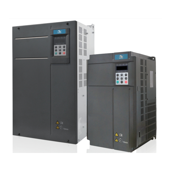
Chapter 2 Product Information 2.2 Components of the IS580 The IS580 series servo drives have two housing types, plastic housing and sheet metal housing, according to different voltage and power classes. Figure 2-2 Components of the IS580 of plastic housing (three-phase 380 to 480 V, IS580T020-R1-1 to... - Page 17 Chapter 2 Product Information IS580 User Manual Figure 2-4 Components of the IS580 of sheet metal housing (three-phase 380 to 480 V, IS580T080-R1-H-1 to IS580T210-R1-H-1) Front cover Inovance logo Operating panel Control board Filter capacitor Power terminals Housing - 16 -...
-
Page 18: Technical Specifications
IS580 User Manual Chapter 2 Product Information 2.3 Technical Specifications Table 2-1 Technical specifications of the IS580 Item Description Standard Max. frequency 300 Hz functions Carrier frequency 1 to 8 kHz Input frequency resolution Digital setting: 0.01 Hz Analog setting: Max. frequency x 0.1% Control mode Closed-loop vector control (CLVC), voltage/frequency (V/F) control Startup torque... - Page 19 Chapter 2 Product Information IS580 User Manual - 18 -...
-
Page 20: Chapter 3 Mechanical And Electrical Installation
Mechanical and Electrical Installation... -
Page 21: Mechanical Installation
■ The mechanical clearance requirements for the IS580 vary with power classes of the servo drive. Figure 3-1 Mounting clearance of the IS580 Installation clearance requirements on the IS580 series servo drives of different power classes Hot air Power Class... - Page 22 Chapter 3 Mechanical and Electrical Installation The IS580 series servo drive dissipates heat from the bottom to the top. The drive of IS580T080-R1-H-1 to IS580T210-R1-H-1dissipates heat from the left to the right. When multiple servo drives are required to work together, install them side by side.
- Page 23 Chapter 3 Mechanical and Electrical Installation IS580 User Manual Embedded mounting the IS580 of plastic housing (IS580T020-R1-1 to IS580T070-R1-1) Figure 3-4 External hanging bracket for the IS580 of plastic housing External hanging bracket Figure 3-5 Embedded mounting of the IS580 of plastic housing Install the servo drive from the front of the control cabinet.
- Page 24 IS580 User Manual Chapter 3 Mechanical and Electrical Installation Surface mounting of the IS580 of sheet metal housing (IS580T080-R1-1 to IS580T210-R1-1) Figure 3-6 Surface mounting of the IS580 of sheet metal housing Install the servo drive from the front of the control cabinet. Back panel of the control cabinet Fix four screws.
- Page 25 Chapter 3 Mechanical and Electrical Installation IS580 User Manual Embedded mounting of the IS580 of sheet metal housing (IS580T080-R1-1 to IS580T210-R1-1) Figure 3-8 External hanging bracket for the IS580 of sheet metal housing External bracket External bracket Figure 3-9 Embedded mounting of the IS580 of sheet metal housing Install the servo drive from the front of the control cabinet.
- Page 26 IS580 User Manual Chapter 3 Mechanical and Electrical Installation Embedded mounting of the IS580 of sheet metal housing (IS580T080-R1-H-1 to IS580T210-R1-H-1) Figure 3-10 Embedded mounting from the cabinet front Back panel of the Installation effect Install the servo drive from the control cabinet front of the control cabinet M6 screw x 18...
- Page 27 3.1.4 Removal of the Front Cover For the IS580 series servo drives, you need to remove the front cover before wiring the main circuit and control circuit. The following figures show how to remove the front cover of the IS580.
-
Page 28: Wiring Mode
Chapter 3 Mechanical and Electrical Installation 3.2 Wiring Mode The wiring of the IS580 series servo drive is shown in the foldout at the end of this chapter. 3.3 Main Circuit Terminals and Wiring Figure 3-15 Terminal arrangement of the main circuit... -
Page 29: Control Circuit Terminals And Wiring
Chapter 3 Mechanical and Electrical Installation IS580 User Manual 3.4 Control Circuit Terminals and Wiring Figure 3-17 The control circuit terminal arrangement RJ45 KEYBOARD Terminal arrangement of the IS580 control board T/A1 T/B1 T/C1 T/A2 T/C2 T/A3 T/C3 AI1 AI2 AI3 GND 10V 13V GND AO1 AO2 GND COM DI1 DI2 DI3 DI4 DI5 COM OP 24V PTCP PTVN CANHCANL CGND 485B 485A Function Description of Jumpers of the IS580... - Page 30 IS580 User Manual Chapter 3 Mechanical and Electrical Installation Description of Control Circuit Terminals ■ Type Terminal Name Description Provide +10 V±10% power supply externally. Generally, it provides power supply to the external potentiometer with +10V-GND +10 V power supply resistance range of 1 to 5 kΩ.
-
Page 31: Description Of Pg Card Terminals On The Is580
Chapter 3 Mechanical and Electrical Installation IS580 User Manual Type Terminal Name Description Voltage or current output is decided by jumper J4. Output range: 0–10 V/0–20 mA AO1-GND Analog output 1 12-bit resolution, correction accuracy 1%, maximum load resistance value ≤ 500 Ω Analog output Voltage or current output is decided by jumper J6. - Page 32 IS580 User Manual Chapter 3 Mechanical and Electrical Installation Figure 3-18 Connecting the PG card to the motor (1) POWER MOTOR COS- COS+ SIN- SIN+ REF- REF+ KTY- KTY+ PTC- PTC+ Figure 3-19 Connecting the PG card to the motor (2) Built-in PG card MF38PG4A1 Yellow-...
-
Page 33: Wiring The External Braking Unit
Chapter 3 Mechanical and Electrical Installation IS580 User Manual 3.6 Wiring the External Braking Unit Two wiring methods are provided, differing in the wiring of braking resistor overheat protection. Wiring method 1: After the signal of the braking resistor overheat relay is sent, the power supply of the IS580 is cut off. -
Page 34: Wiring Diagram Of System Application
IS580 User Manual Chapter 3 Mechanical and Electrical Installation Figure 3-21 Basic wiring method 2 Circuit breaker IS580 Braking unit servo drive P(+) - + In this wiring method, the braking unit is connected to COM on one side and DIx on the other side. The function code setting is as follows when the braking unit is connected to different DI terminals: DI1: F4-00 = 11;... -
Page 35: Use Of The Operation Panel
Chapter 3 Mechanical and Electrical Installation IS580 User Manual 3.8 Use of the Operation Panel The IS580 has a built-in LED operation panel. An external LED operation panel can also be connected to the RJ45 interface of the IS580 by an 8-core flat cable. You can modify the parameters, monitor the working status and start or stop the IS580 by operating the operation panel, as shown in the following figure. - Page 36 IS580 User Manual Chapter 3 Mechanical and Electrical Installation FWD/REV • ON indicates reverse rotation, and OFF indicates forward rotation. TUNE/TC • When the indicator is ON, it indicates torque control mode. When the indicator is blinking slowly, it indicates the auto-tuning state.
- Page 37 Chapter 3 Mechanical and Electrical Installation IS580 User Manual 3.8.3 Viewing and Modifying Function Codes The operation panel of the IS580 adopts three-level menu. The three-level menu consists of function code group (Level I), function code (Level II), and function code setting value (level III), as shown in the following figure.
- Page 38 IS580 User Manual Chapter 3 Mechanical and Electrical Installation In the stop or running state, the operation panel can display multiple status parameters. In the stop state, you can press to view the parameters circularly. For details on the parameters that can be displayed, see the description of group U0.
- Page 39 Chapter 3 Mechanical and Electrical Installation IS580 User Manual 3.8.4 Password Setting The servo drive provides the user password protection function. The following figure shows how to set the password to 1234. Figure 3-27 Setting the password Status parameter (Default display) 1500 Return Switchover...
- Page 40 IS580 User Manual Chapter 3 Mechanical and Electrical Installation User-defined Group ■ The user-defined menu is set to facilitate viewing and modifying of commonly used function codes. In this mode, the display parameter uF3.02 indicates function code F3-02. You can also modify parameters in this mode as in common editing state.
- Page 41 Chapter 3 Mechanical and Electrical Installation IS580 User Manual In the non-oil pressure control mode, deleting function codes from the user-defined group is as shown in the following figure. Figure 3-29 Deleting function codes from the user-defined group User-defined mode (Only the user-defined function codes are available) uF1.03...
- Page 42 IS580 User Manual Chapter 3 Mechanical and Electrical Installation 3.8. 6 Starting or Stopping the Servo Drive Selecting the Start/Stop Command Source ■ There are three start/stop command sources, namely, operation panel control, terminal control, and communication control. You can select the command source in F0-02. Function Code Parameter Name Setting Range Description Default...
- Page 43 For details on the communication protocols, consult Inovance. 3.8.7 Setting the Running Frequency The IS580 supports two control modes: speed mode and oil pressure mode, set in A3-00. In the speed mode, there are six frequency setting sources, digital setting (UP/DOWN modification, non-retentive at power failure), (UP/DOWN modification, retentive at power failure), AI1, AI2, AI3, and communication setting.
- Page 44 90 kW and above Braking resistor 75 kW and below Braking unit MDBUN Braking resistor P(+) – – Braking resistor MDBUN Braking unit Breaker Contactor Loop magnetic ring MCCB MC (wind it a turn) Filter – Servo pump Three-phase AC COS- COS+ SIN-...
-
Page 45: Chapter 4 Servo Pump Commissioning
Servo Pump Commissioning... -
Page 46: Servo Pump Commissioning Flowchart
Chapter 4 Servo Pump Commissioning IS580 User Manual Chapter 4 Servo Pump Commissioning 4.1 Servo Pump Commissioning Flowchart The servo pump commissioning process mainly includes motor auto-tuning, motor trial running, and servo oil pressure commissioning, as shown in the following figure. Figure 4-1 Servo pump commissioning flowchart Start Control mode: A3-00 = 0... -
Page 47: Motor Trial Running
IS580 User Manual Chapter 4 Servo Pump Commissioning 4.2 Motor Trial Running 4.2.1 Procedure of Motor Trial Running Step Parameter Setting Parameter Description Remarks 1. Set the control mode. A3-00 = 0 Non-hydraulic control mode Set the non-hydraulic control mode. 2. - Page 48 Chapter 4 Servo Pump Commissioning IS580 User Manual Motor Auto-tuning Setting ■ Auto-tuning Mode Function Code Setting Application After motor auto-tuning is completed, the value of F1-16 is restored No operation F1-16 = 0 to 0 automatically. This mode is used when the back EMF of the motor is known. Static auto-tuning 1 F1-16 = 1 The motor runs at a low speed during auto-tuning, and therefore,...
- Page 49 IS580 User Manual Chapter 4 Servo Pump Commissioning Motor Auto-tuning Procedure ■ Figure 4-2 Motor auto-tuning procedure Power on the servo drive. After motor auto-tuning is completed, Set F0-02 to 0 (Operation panel perform trial running: Set F0-08 to control) and F1-00 = 2 (PMSM). 5.00 (Hz), and Press RUN.
-
Page 50: Application Commissioning Of Servo Pump
Chapter 4 Servo Pump Commissioning IS580 User Manual 4.3 Application Commissioning of Servo Pump 4.3.1 AI Zero Drift Auto Correction Step Function Code Setting Parameter Description Remarks 1. Set the command The operation panel control F0-02 = 0 The LOCAL/REMOT indicator is OFF. source. - Page 51 IS580 User Manual Chapter 4 Servo Pump Commissioning Function Code Parameter Name Setting F4-00 DI1 function selection 1: Forward RUN (FWD enabled) F4-01 DI2 function selection 48: Servo pump PID selection terminal 1 F4-02 DI3 function selection 53: Slave pump address selection terminal 1 F4-03 DI4 function selection 9: Fault reset (RESET)
- Page 52 Chapter 4 Servo Pump Commissioning IS580 User Manual Oil Presure PID Proportional Gain (A3-05, A3-11, A3-14, and A3-17) ■ The larger the proportional gain, the faster the system response. Too large setting will cause system oscillation, but too small setting will slow the system response. Figure 4-3 Relationship between the proportional gain and system response Pressure P pressure...
- Page 53 IS580 User Manual Chapter 4 Servo Pump Commissioning Oil Pressure Overshoot Suppression (A3-27/A4-16, A3-28/A4-17) ■ This function is used for pressure overshoot suppression at high speed. Overshoot suppression detection level (A3-27/A4-16) • The larger the value of the parameter is, the later the overshoot suppression starts, the poorer the suppression effect becomes, and the bigger the overshoot will be.
- Page 54 Chapter 4 Servo Pump Commissioning IS580 User Manual - 52 -...
- Page 55 Maintenance and Trouble-shooting...
-
Page 56: Chapter 5 Maintenance And Troubleshooting
Chapter 5 Maintenance and Troubleshooting IS580 User Manual Chapter 5 Maintenance and Troubleshooting 5.1 Maintenance of the Servo Drive 5.1.1 Daily Maintenance The influence of the ambient temperature, humidity, dust and vibration will cause the aging of the devices in the servo drive, which may cause potential faults or reduce the service life of the servo drive. -
Page 57: Warranty Agreement
Free warranty only applies to the servo drive itself. Inovance will provide 18-month warranty from date of manufacturing for the failure or damage under normal use conditions. If the equipment has been used for over 18 months, reasonable repair expenses will be charged. -
Page 58: Troubleshooting
Before contacting Inovance for technical support, you can first determine the fault type, analyze the causes, and perform troubleshooting according to the description in this chapter. If the fault cannot be rectified, contact the agent or Inovance. - Page 59 IS5800 User Manual Chapter 5 Maintenance and Troubleshooting 5.3.1 Troubleshooting flowchart Figure 5-1 Err02 (Overcurrent during acceleration) Err02 Check whether the servo drive output circuit is Eliminate external faults. earthed or short circuited. V/F control Check whether motor auto-tuning Perform motor auto-tuning. is performed properly.
- Page 60 Check whether the braking unit and braking Install the braking unit and braking resistor are installed. resistor. Contact the agent or Inovance. Figure 5-3 Err04 (Overcurrent at constant speed) Err04 Eliminate external faults. Install Check whether the servo drive output circuit is an output reactor if the cable is earthed or has leakage current.
- Page 61 Install the braking unit and braking Check whether the braking unit and braking resistor. resistor are installed. Contact the agent or Inovance. Figure 5-5 Err06 (Overvoltage during deceleration) Err06 Check whether the input voltage of the Adjust the input voltage to the normal servo drive is too high.
- Page 62 Remove the external force or Check whether there is an external force to drive install a braking resistor. the motor during acceleration. Contact the agent or Inovance. Figure 5-7 Err09 (Undervoltage) Err09 Check whether instantaneous power failure occurs. Perform the reset operation.
- Page 63 Clear the air filter. Check whether the cooling fan is damaged. Replace the cooling fan. Contact the agent or Inovance. Check whether the module thermistor is damaged. Replace the thermistor. Check whether the inverter module is damaged. Replace the inverter module.
- Page 64 Check whether communication parameters Set the communication are set properly. parameters properly. Contact the agent or Inovance. Figure 5-14 Err17 (Contactor fault) Err17 Check whether the drive board and power Replace the drive board or supply are normal.
- Page 65 IS5800 User Manual Chapter 5 Maintenance and Troubleshooting Figure 5-15 Err18 (Current detection fault) Contact the agent or Inovance. Err18 Check whether hall devices are normal. Replace the hall devices. Check whether the drive board is normal. Replace the drive board.
- Page 66 Replace the servo drive. Figure 5-20 Err26 (Accumulative running time reached) Err26 Check whether F7-09 (Accumulative Contact the agent or Inovance. running time) is equal to or greater than F8-17 (Set accumulative running time) Do you want the servo drive to continue running? Stop the servo drive.
- Page 67 Increase the capacity level of the after increasing the capacity level of the servo drive. servo drive. Contact the agent or Inovance. Figure 5-23 Err42 (CAN communication interrupted) Err42 Set correct CAN communication Check whether the CAN communication parameters A2- parameters.
- Page 68 Eliminate the wiring fault. Check whether the encoder wiring is correct. Contact the agent Install the encoder correctly. or Inovance. Check whether the encoder installation is correct. Check whether the encoder becomes normal It is PG card fault. after the PG card is replaced.
- Page 69 Eliminate the power supply fault. pressure sensor is normal. Contact the agent Check whether the output of the pressure Replace the pressure sensor. or Inovance. sensor is normal. Check whether it it normal after the terminal It is terminal block fault. block is replaced.
- Page 70 Figure 5-30 Err59 (Back EMF auto-tuning fault) Err5 9 Contact the agent or Check motor parameters in group F1 are Set motor parameters correctly. Inovance. set correctly. Replace the motor and contact Replace with a motor of the same type to motor manufacturer to find the check whether the motor is demagnetized.
-
Page 71: Symptoms And Diagnostics
1. Check the power input. servo drive. 2. Connect the 8-core cable again. 2. The 8-core cable connecting the 3. Contact the agent or Inovance. drive board and the control board is in poor contact. 3. Components inside the servo drive are damaged. - Page 72 The soft startup contactor is not 1. Check: power-on or running. closed. Whether the contactor cable is loose Whether the contactor is faulty Whether the contactor 24 V power supply is faulty. 2. Contact the agent or Inovance. - 70 -...
- Page 73 ISMG Servo Motor...
-
Page 74: Chapter 6 Ismg Servo Motor (Voltage Class: 400 V)
Chapter 6 ISMG Servo Motor (Voltage Class: 400 V) IS580 User Manual Chapter 6 ISMG Servo Motor (Voltage Class: 400 V) 6.1 Designation Rules of the ISMG Servo Motor ISM G1- 30D 15C D- R1 3 1 F Mark Customized Requirement Mark Series No. -
Page 75: Ismg Servo Motor Specification Parameters
IS580 User Manual Chapter 6 ISMG Servo Motor (Voltage Class: 400 V) 6.2 ISMG Servo Motor Specification Parameters 6.2.1 ISMG1 Servo Motor (200 x 200 Base/Forced Air Cooling) Specifications of the ISMG1 motor with forced air cooling Servo Motor Model Rated Torque Rated Motor Back EMF... - Page 76 Chapter 6 ISMG Servo Motor (Voltage Class: 400 V) IS580 User Manual 6.2.2 ISMG2 Servo Motor (266 x 266 Base/Forced Air Cooling) Specifications of the ISMG1 motor with forced air cooling Servo Motor Model Rated Torque Rated Motor Back EMF Rated Rated No-load...
-
Page 77: Physical Appearance And Mounting Dimensions Of Ismg Servo Motor
IS580 User Manual Chapter 6 ISMG Servo Motor (Voltage Class: 400 V) 6.3 Physical Appearance and Mounting Dimensions of ISMG Servo Motor 6.3.1 ISMG1 Servo Motor (200 x 200 Base/Forced Air Cooling) Figure 6-1 Physical appearance and mounting dimensions of the ISMG1 servo motor (200 x 200 base/forced air cooling) Standard configuration: A-type round-end parallel key 12 x 8 x 56 Refer to GB/T 1096... -
Page 78: Supporting Board Of Ismg Servo Motor Base
Chapter 6 ISMG Servo Motor (Voltage Class: 400 V) IS580 User Manual 6.3.2 ISMG2 Servo Motor (266 x 266 Base/Forced Air Cooling) Figure 6-2 Physical appearance and mounting dimensions of the ISMG2 servo motor (266 x 266 base/forced air cooling) Standard configuration: A-type round-end parallel key 14 x 9 x 90 Refer to GB/T1096 Table 6-2 Mounting dimensions of the ISMG2 servo motor (266 x 266 base/forced air cooling) -
Page 79: Wiring Of The Ismg Servo Motor
IS580 User Manual Chapter 6 ISMG Servo Motor (Voltage Class: 400 V) 6.5 Wiring of the ISMG Servo Motor 6.5.1 Terminals of PCB Board The signal types of the terminals are defined on the PCB board. AC1 and AC2 are power supply (single-phase 220 V) to the cooling fan. -
Page 80: Cleaning The Cooling Fan Of The Servo Motor
Chapter 6 ISMG Servo Motor (Voltage Class: 400 V) IS580 User Manual 6.6 Cleaning the Cooling Fan of the Servo Motor The estimated service life of the cooling fan of the servo motor is 40000 hours. On the condition that the cooling fan runs continuously at full speed, rated voltage and 40°C ambient temperature, after the cooling fan is jammed with foreign matters, the performance of the cooling fan degrades and the air volume reduces. - Page 81 Selection...
-
Page 82: Chapter 7 Selection
Chapter 7 Selection IS580 User Manual Chapter 7 Selection 7.1 Technical Data of the IS580 Model Power Capacity Input Current Output Current Adaptable Motor Thermal Power Consumption (kW) (kVA) (kW, HP) Three-phase 440 V, 50/60 Hz IS580T020-R1-1 36.3 0.445 IS580T030-R1-1 45.1 0.553 IS580T035-R1-1... -
Page 83: Selection Of Braking Unit And Braking Resistor
IS580 User Manual Chapter 7 Selection 7.2 Selection of Braking Unit and Braking Resistor Servo drive Model Recommended Recommended Braking Unit Remark Power of Braking Resistance of Resistor Braking Resistor Three-phase 380 to 480 V IS580T020-R1-1 800 W ≥ 43 Ω Built-in IS580T030-R1-1 1000 W... -
Page 84: Mounting Dimensions Of The Is580
Chapter 7 Selection IS580 User Manual Servo drive Model Servo drive MCCB Contactor Cable of Input Cable of Output Cable of Main Circuit Rated Input Side Main Side Main Control Grounding Current Circuit (mm Circuit (mm Circuit (mm Cable (mm IS580T100-R1-1 106.00 0.75... - Page 85 IS580 User Manual Chapter 7 Selection Figure 7-2 Mounting dimensions of IS580 sheet metal housing (IS580T080-R1-1 to IS580T210-R1-1) Table 7-1 Mounting dimensions of IS580 sheet metal housing (IS580T080-R1-1 to IS580T210-R1-1) Servo drive Model Mounting Hole Overall Dimensions (mm) Mounting Weight (mm) Hole Diameter (kg)
- Page 86 Chapter 7 Selection IS580 User Manual Figure 7-3 Mounting dimensions of IS580 sheet metal housing (IS580T080-R1-H-1 to IS580T210-R1-H-1) 272.5 G1/2 internal thread 18- 7 - 84 -...
-
Page 87: Mounting Dimensions Of Power Terminals And Recommended Cable Diameter
IS580 User Manual Chapter 7 Selection 7.5 Mounting Dimensions of Power Terminals and Recommended Cable Diameter Note • The data and models recommended in the table are for reference only. The diameter of the cable the use selects must not exceed the terminal dimensions in the figure. •... - Page 88 Chapter 7 Selection IS580 User Manual Table 7-3 Cable dimensions and tightening torque of IS580T050/070 Servo drive Model Rated Input Recommended Cable Tightening Torque Recommended Current (A) Diameter (mm (N·m) Cable Lug Model IS580T050-R1-1 GTNR16-6 IS580T070-R1-1 GTNR25-6 Figure 7-6 Terminal dimensions of IS580T080/100 26.8 24.8 POWER...
- Page 89 IS580 User Manual Chapter 7 Selection Table 7-5 Cable dimensions and tightening torque of IS580T140/170/210 Servo drive Model Rated Input Recommended Cable Tightening Torque Recommended Current (A) Diameter (mm2) (N·m) Cable Lug Model IS580T140-R1-1 35.0 GTNR70-12 IS580T140-R1-H-1 IS580T170-R1-1 35.0 GTNR70-12 IS580T170-R1-H-1 IS580T210-R1-1 35.0...
- Page 90 Chapter 7 Selection IS580 User Manual Table 7-7 Models and dimensions of the GTNR series cable lugs Cable Lug Model D Crimping Tool GTNR1.5-5 16.0 RYO-8 YYT-8 GTNR2.5-4 18.0 RYO-14 GTNR2.5-5 20.0 GTNR2.5-6 10.2 GTNR4-5 10.0 20.0 GTNR4-6 GTNR6-5 10.0 23.0 GTNR6-6 26.0...
-
Page 91: Mounting Dimensions Of Optional Parts
IS580 User Manual Chapter 7 Selection 7.6 Mounting Dimensions of Optional Parts 7.6.1 Mounting Dimensions of the External Braking Unit Note The servo drive of IS580T170-R1-1 and above has the built-in DC reactor. Figure 7-11 Physical appearance and mounting dimensions of the MDBUN series braking unit 7.6.2 Physical Dimensions of External Operation Panel Figure 7-12 Physical dimensions of external operation panel 27.0... - Page 92 Chapter 7 Selection IS580 User Manual - 90 -...
-
Page 94: Definition Of Terms
Chapter 8 EMC IS580 User Manual Chapter 8 EMC 8.1 Definition of Terms ■ Electromagnetic compatibility (EMC) describes the ability of electronic and electrical devices or systems to work properly in the electromagnetic environment and not to generate electromagnetic interference that influences other local devices or systems. -
Page 95: Introduction To Emc Standard
2006/95/EC EN 61800-5-1 93/68/EEC The IS580 series servo drive satisfies the requirements of standard EN 61800-3. 2004 Category C2. The Servo drives are applied to both the first environment and the second environment. 8.2.3 Installation Environment The system manufacturer using the servo drive is responsible for compliance of the system with the European EMC directive. -
Page 96: Selection Of Peripheral Emc Devices
The IS580 series servo drive satisfies the requirements of category C2 only with an EMC filter installed on the power input side. The installation precautions are as follows: Strictly comply with the ratings when using the EMC filter. - Page 97 IS580 User Manual Chapter 8 EMC The following table lists the recommended manufacturers and models of EMC filters for the IS580 series servo drive. Select a proper one based on actual requirements. Table 8-1 Recommended manufacturers and models of EMC filters...
- Page 98 Chapter 8 EMC IS580 User Manual Selection of the simple EMC filter • Servo Drive Model Simple EMC Filter Rated Current Overall Dimensions Mounting Dimensions Filter Model (Length x Width x Height) (Mounting Length x Mounting Width) IS580T020-R1-1 DL65EB1/10 218 x 140 x 80 184 x 112 IS580T030-R1-1 IS580T035-R1-1...
- Page 99 The following table lists the recommended manufacturers and models of input reactors. Table 8-2 Recommended manufacturers and models of AC input reactors Servo drive Model AC Input Reactor Model Reactor Rated Current (Inovance) IS580T020-R1-1 MD-ACL-40-4T-153-2% IS580T030-R1-1 MD-ACL-50-4T-183-2% IS580T035-R1-1...
- Page 100 280 to 690 The following table lists the recommended manufacturer and models of AC output reactors. Table 8-4 Recommended manufacturer and models of AC output reactors Servo drive Model AC Output Reactor Model Reactor Rated Current (Inovance) IS580T020-R1-1 MD-OCL-30-4T-113-1% IS580T030-R1-1 MD-OCL-40-4T-153-1% IS580T035-R1-1...
-
Page 101: Shielded Cable
IS580 User Manual Chapter 8 EMC 8.4 Shielded Cable 8.4.1 Requirements for Shielded Cable The shielded cable must be used to satisfy the EMC requirements of CE marking. Shielded cables are classified into three-conductor cable and four-conductor cable. If conductivity of the cable shield is not sufficient, add an independent PE cable, or use a four-conductor cable, of which one phase conductor is PE cable. - Page 102 Chapter 8 EMC IS580 User Manual The installation precautions are as follows: Symmetrical shielded cable is recommended. The four-conductor shielded cable can also be used as an input cable. The motor cable and PE shielded conducting wire (twisted shielded) should be as short as possible to reduce electromagnetic radiation and external stray current and capacitive current of the cable.
-
Page 103: Solutions To Common Emc Interference Problems
IS580 User Manual Chapter 8 EMC 8.5 Solutions to Common EMC Interference Problems The servo drive generates very strong interference. Although EMC measures are taken, the interference may still exist due to improper cabling or grounding during use. When the servo drive interferes with other devices, adopt the following solutions. - Page 104 Chapter 8 EMC IS580 User Manual - 102 -...
- Page 105 Function Code Table...
-
Page 106: Chapter 9 Function Code Table
Chapter 9 Function Code Table IS580 User Manual Chapter 9 Function Code Table Function Name LED Display Setting Range Min. Unit Default Property Code Group U0: View Servo Drive Parameters U0-00 Running frequency Running frequency 0.00 Hz to maximum ● frequency (F0-10) U0-01 Set frequency... - Page 107 IS580 User Manual Chapter 9 Function Code Table Function Name LED Display Setting Range Min. Unit Default Property Code U1-03 Motor speed Motor speed -9999 to 30000 RPM ● U1-04 AI1 voltage AI1 voltage -10.00 to 10.000 V ● U1-05 AI2 voltage AI2 voltage -10.00 to 10.000 V...
- Page 108 Chapter 9 Function Code Table IS580 User Manual Function Name LED Display Setting Range Min. Unit Default Property Code A1-02 Encoder installation Encoder installation 0.0° to 359.9° 0.1° 0.0° ☆ angle angle A1-03 Inversion of feedback Inversion of feedback 0: Consistent ★...
- Page 109 IS580 User Manual Chapter 9 Function Code Table Function Name LED Display Setting Range Min. Unit Default Property Code A3-02 System oil pressure System oil pressure 0.0 kg/cm to maximum oil 0.0 kg/cm 175.0 kg/ ☆ pressure (A3-03) A3-03 Max. oil pressure Max.
- Page 110 Chapter 9 Function Code Table IS580 User Manual Function Name LED Display Setting Range Min. Unit Default Property Code A3-26 S-curve fall filter time of S-curve fall filter time of 0.000s to 1.000s 0.001s 0.020s ☆ set oil pressure set oil pressure A3-27 Overshoot suppression Overshoot suppression...
- Page 111 IS580 User Manual Chapter 9 Function Code Table Function Name LED Display Setting Range Min. Unit Default Property Code A3-43 Pressure deviation of Pressure deviation of 0 to 50.0 kg 0.1 kg 5.0 kg ☆ slave pump not working slave pump not working in the CAN multi-pump in the CAN multi-pump mode...
- Page 112 Chapter 9 Function Code Table IS580 User Manual Function Name LED Display Setting Range Min. Unit Default Property Code A4-09 Long-time running Long-time running 0.001s to 5.000s 0.001s 0.000s ☆ protective time of protective time of reverse pressure relief reverse pressure relief A4-10 Injection S-curve rise Injection S-curve rise...
- Page 113 IS580 User Manual Chapter 9 Function Code Table Function Name LED Display Setting Range Min. Unit Default Property Code F0-02 Command source Command source 0: Operation panel (LED ☆ selection selection OFF) 1: Terminal (LED ON) 2: Communication setting (LED blinking) F0-03 Main frequency source Main frequency source...
- Page 114 Chapter 9 Function Code Table IS580 User Manual Function Name LED Display Setting Range Min. Unit Default Property Code F0-17 Acceleration time 1 Acceleration time 1 0.0s to 6500.0s 0.1s 20.0s ☆ F0-18 Deceleration time 1 Deceleration time 1 0.0s to 6500.0s 0.1s 20.0s ☆...
- Page 115 IS580 User Manual Chapter 9 Function Code Table Function Name LED Display Setting Range Min. Unit Default Property Code F1-16 Motor auto-tuning mode Motor auto-tuning mode 0: No operation ★ 1: No-load static auto-tuning 2: No-load dynamic auto- tuning, rotating at high speed in reverse direction 3: With-load static auto- tuning...
- Page 116 Chapter 9 Function Code Table IS580 User Manual Function Name LED Display Setting Range Min. Unit Default Property Code F2-11 Torque filter bandwidth Torque filter bandwidth 0 to 1500 Hz 1 Hz 500 Hz ☆ F2-12 Reserved ★ F2-13 Current loop low-speed Current loop low-speed 0.2 to 5.0 ★...
- Page 117 IS580 User Manual Chapter 9 Function Code Table Function Name LED Display Setting Range Min. Unit Default Property Code F4-05 to Reserved 51: Slave pump enabled as ★ F4-14 master pump 52: Switchover from pressure mode to speed mode 53: Slave pump address selection terminal 1 54: Slave pump address selection terminal 2...
- Page 118 Chapter 9 Function Code Table IS580 User Manual Function Name LED Display Setting Range Min. Unit Default Property Code F4-33 to Reserved ☆ F4-58 Group F5: Output Terminals F5-00 Reserved ☆ F5-01 Control board relay (T/ Control board relay (T/ 0: No output ☆...
- Page 119 IS580 User Manual Chapter 9 Function Code Table Function Name LED Display Setting Range Min. Unit Default Property Code F5-11 AO2 output selection AO2 output selection 2: Output current ☆ 3: Output torque 4: Output power 5: Output voltage 6: Reserved 7: AI1 8: AI2 9: AI3...
- Page 120 Chapter 9 Function Code Table IS580 User Manual Function Name LED Display Setting Range Min. Unit Default Property Code F7-06 Load speed display Load speed display 0.0001 to 6.5000 0.0001 1.0000 ☆ coefficient coefficient F7-07 Heatsink temperature 1 Heatsink temperature 1 0.0°C to 100°C 1°C ●...
- Page 121 IS580 User Manual Chapter 9 Function Code Table Function Name LED Display Setting Range Min. Unit Default Property Code F9-14 Runaway speed Runaway speed 0.50 to 50.00 Hz 0.01 Hz 10.00 Hz ☆ deviation deviation F9-15 Detection time of Detection time of 0.1s to 20.0s 0.1s 10.0s...
- Page 122 Chapter 9 Function Code Table IS580 User Manual Function Name LED Display Setting Range Min. Unit Default Property Code F9-20 Latest fault type Latest fault type 22: Reserved (Err22) ☆ 23: : Short circuit to ground (Err23) 24 and 25: Reserved 26: Accumulative running time reached 27: Business running time...
- Page 123 IS580 User Manual Chapter 9 Function Code Table Function Name LED Display Setting Range Min. Unit Default Property Code F9-22 Current at fault Current at fault 0.1 A ● occurrence occurrence F9-23 Bus voltage at fault Bus voltage at fault 0.1 V ●...
- Page 124 FD-05 Communication Communication protocol 0: Standard Modbus ☆ protocol protocol, used for host computer parameter reading/writing and running control 1: Inovance private protocol, used for communication with background oscilloscope Group FP: User Password FP-00 User password User password 0–65535 ☆...
- Page 125 Appendix...
-
Page 126: Appendix A Leakage Current Suppression Solution And Leakage Protector Selection
Chapter 10 Appendix IS580 User Manual Appendix A Leakage Current Suppression Solution and Leakage Protector Selection Note In the following tables, • "-" indicates that the leakage current suppression solution does not cover the power. • The residual current circuit breaker (RCCB), RCD and leakage protector indicate the same concept. Servo Drive Model Solution 1: Require Leakage Current During Running <... - Page 127 IS580 User Manual Chapter 10 Appendix Servo Drive Solution 1: Require Leakage Current During Running < 100 mA (Use Wind the Magnetic Ring Three Model Turns and Use the Safety Capacitance Box). Leakage Leakage Magnetic Safety Installation Wiring Diagram Leakage Protector Protector Ring Model...
- Page 128 Chapter 10 Appendix IS580 User Manual Servo Drive Model Solution 3: Require Leakage Current During Running < 200 mA (Wind the Magnetic Ring One Turn and Use the Safety Capacitance Box). Magnetic Ring Installation Wiring Diagram Leakage Protector Model Selection Reserved DY644020H For selection of the safety capacitance box, refer to...
- Page 129 IS580 User Manual Chapter 10 Appendix Servo Drive Model Solution 4: Require Leakage Current During Running Reducing 50% (Wind the Input or Output Magnetic Ring Three Turns). Magnetic Ring Model Installation Wiring Diagram Leakage Protector Selection Reserved DY644020H For the wiring diagram of winding the output Action current UVW cable three turns, for the wiring diagram I△n...
- Page 130 Chapter 10 Appendix IS580 User Manual Servo Drive Model Solution 5: Require Leakage Current During Running Reducing 25% (Wind the Input or Output Magnetic Ring One Turn). Magnetic Ring Model Installation Wiring Diagram Leakage Protector Selection Reserved DY644020H I△n Action current ≥...
-
Page 131: Appendix B Multi-Pump Control Of Imm
IS580 User Manual Chapter 10 Appendix Appendix B Multi-pump Control of IMM B.1 Parallel Pump Control The parallel pump control is classified into multi-pump convergent flow and multi-pump distributed flow. The multi-pump convergent flow • A servo drive is used as the master drive, and the other drives are used as slave drives connected in parallel. The host computer outputs a set of flow and pressure analog signals. - Page 132 Chapter 10 Appendix IS580 User Manual Note • For detailed wiring and CAN communication wiring, refer to the foldouts at the end of this chapter. • For the parameter setting, refer to the following related parameter setting part. • You can ensure the same motor speed through the communication. The following figure shows the multi-pump distributed flow structure chart.
-
Page 133: Multi-Pump Control Mode
IS580 User Manual Chapter 10 Appendix B.2 Multi-pump Control Mode Function Code Parameter Name Setting Range A2-03 CAN multi-pump mode 0: Multi-pump 1 (old mode) 1: Multi-pump 2 (new mode) Multi-pump 1 • This mode is the old mode and is applicable to simple multi-pump control. When the slave pump is switched over to the master pump, the slave pump cannot be controlled. - Page 134 Chapter 10 Appendix IS580 User Manual CAN Communication Wiring ■ The CAN bus connection of all pumps is shown in the following figure. Figure B-3 CAN bus connection of all pumps Slave drive 2 Master drive Slave drive 1 CANL CANL CANL CANH...
- Page 135 IS580 User Manual Chapter 10 Appendix For example: Condition 1: Suppose the max. pressure holding speed of the master is 50 rpm/min., the max. speed of the master is 2000 rpm/min., and the max. speed of the slave is 2000 rpm/min. Condition 2: At pressure hoding, the master works and the slave stops.
-
Page 136: Parameter Setting On Master Drive
Chapter 10 Appendix IS580 User Manual B.3 Parameter Setting on Master Drive Multi-pump mode 1 (A2-03 = 0) • The parameter setting is simple. For all servo drives, allocate a DI terminal for the 50# function and set it to Function Code Parameter Name Setting Description... -
Page 137: Parameter Setting On Slave Drive
IS580 User Manual Chapter 10 Appendix Description of slave pump address setting • The LED display of the slave pump address setting is as follows: Note • The numbers in the LED display correspond to the slave pump address station No. •... -
Page 138: Applications Of Multi-Pump Convergent And Distributed Flow Control
Chapter 10 Appendix IS580 User Manual Multi-pump mode 2 (A2-03 = 1) • The following table lists the parameter setting of the slave drive. Perform the same parameter setting as you do in the common servo pump mode. Function Code Parameter Name Setting Description A2-01... - Page 139 IS580 User Manual Chapter 10 Appendix Note • Because the 1# pump is always the master pump and the 2# pump alaways the slave pump, directly short the DI terminal set for the 50# function. • The 3# pump switches over to the master pump in the following combination 2, which requires an external switchover signal.
- Page 140 Chapter 10 Appendix IS580 User Manual B.5.2 Multi-pump Mode 2 (A2-03 = 1) For example, the IMM servo pump system consists of four pumps with the address set as 1#, 2#, 3# and 4#. There are the follwoing three combinations: Combination 1: 4-pump convergent flow •...
- Page 141 IS580 User Manual Chapter 10 Appendix The 1# pump is the master pump, and the 2#, 3# and 4# pumps are slave pumps. The setting of address of corresponding slave pumps in A2-04 is as follows: Combination 2: 2+2 combination for distributed flow control ■...
- Page 142 Chapter 10 Appendix IS580 User Manual In this combination, the 1# pump and 3# pump are the master pumps. The slave pump changes and the address of the slave pump needs to be set. The slave pump of the 1# master pump is 2# pump. The setting of the slave pump address in A2-05 is as follows: The slave pump of the 3# master pump is 4# pump.
-
Page 143: Fault Description
Check whether a fault occurs on the slave. Eliminate the slave fault. Check whether the CAN Eliminate connection fault. Contact the agent or communication connection is wrong. Inovance. Check whether it becomes normal after It is the terminal board fault. replacing the terminal board. - 141 -... - Page 144 Check whether more than one drive suffers fault. station No. fault Check whether the CAN Contact the agent or Eliminate connection fault. communication connection is wrong. Inovance. Check whether it becomes normal after It is the terminal board fault. replacing the terminal board. - 142 -...
- Page 145 Wiring of main circuit and control terminals: Filter Filter Loop magnetic ring Loop magnetic ring MCCB MCCB (Wiring of the braking circuit) (wind it a turn.) Loop magnetic ring (wind it a turn.) (wind it a turn.) Loop magnetic ring (wind it a turn.) (Wiring of braking circuit) Master drive Slave drive...
- Page 146 Wiring of main circuit and control terminals: Filter Filter Loop magnetic ring MCCB MCCB Loop magnetic ring (Wiring of the braking circuit) Wiring of braking circuit (wind it a turn) Loop magnetic ring (wind it a turn) Loop magnetic ring (wind it a turn.) (wind it a turn.) Master drive Slave drive...
- Page 147 Wiring of main circuit and control terminals: Filter Filter Loop magnetic ring Loop magnetic ring MCCB MCCB (Wiring of the braking circuit) (Wiring of braking circuit) Loop magnetic ring (wind it a turn) (wind it a turn) (wind it a turn.) Loop magnetic ring (wind it a turn.) Master drive Slave drive...
- Page 148 Wiring of main circuit and control terminals: Filter Filter Loop magnetic ring Loop magnetic ring MCCB MCCB (Wiring of the braking circuit) (Wiring of braking circuit) (wind it a turn.) Loop magnetic ring (wind it a turn.) (wind it a turn.) Loop magnetic ring (wind it a turn.) Master drive Slave drive...
- Page 149 If there is any failure or damage to the product, please correctly fill out the Product Warranty Card in detail. The maintenance fee is charged according to the latest Maintenance Price List of Inovance. The Product Warranty Card is not re-issued. Please keep the card and present it to the maintenance personnel when asking for maintenance.
-
Page 150: Product Warranty Card
Product Warranty Card Address: Customer information Contact person: Company name: Postcode: Tel or Email: Product model: Serial No (Attach here): Product information Name Supplier who supplied you the unit Failure Description (eg. Fault code) Maintenance personnel:...
Need help?
Do you have a question about the IS580 Series and is the answer not in the manual?
Questions and answers
inovance is580 we forgot the password, is there any other way to open it..
To reset the password for the Inovance IS580 Series servo drive, follow these steps:
1. Access the password setting menu.
2. Navigate to parameter FP-04 (Password for user).
3. Modify the password value (0–65535) using the available controls.
4. Save the new password by pressing ENTER.
If you need to restore default settings, you can use FP-01 (Parameter initialization) and select the appropriate reset option.
This answer is automatically generated