Table of Contents
Advertisement
Quick Links
Advertisement
Table of Contents
Troubleshooting

Related Manuals for Inovance SV630P Series


Summary of Contents for Inovance SV630P Series
-
Page 2: Preface
Preface Introduction Thank you for purchasing the SV630P series servo drive developed by Inovance. It is an economical AC servo drive product, offering a power range from 0.05 kW to 7.5 kW. It comes with Modbus communication interfaces to work with the host controller for a networked operation of multiple servo drives. - Page 3 Preface Description Date Version Added warranty information in the preface. ● Change the name of the magnetic clamp to DYR-130-B. ● Unified the naming rule of the fault code to Er.xxx. ● Changed “General Specifications” to “Product ● Specifications”. Modified motor selection instructions. ●...
- Page 4 ● Warranty Inovance provides warranty service within the warranty period (as specified in your order) for any fault or damage that is not caused by improper operation of the user. You will be charged for any repair work after the warranty period expires.
-
Page 5: Table Of Contents
1.2 Models of MS1-R Series Motors and MS1-Z Series Motors ........20 2 SV630P Series ..................24 2.1 Product Information . - Page 6 Table of Contents 3.4.4 MS1H1-40B30CB-T33*R..............52 3.4.5 MS1H1-55B30CB-T331R .
- Page 7 Table of Contents 3.7.6 MS1H4-10C30CB-T33*R..............87 4 Options ....................
- Page 8 Table of Contents 8.1 Wiring Precautions ................121 8.2 Main Circuit Terminals .
- Page 9 Table of Contents 10.3 Power-on ..................193 10.4 Jog .
- Page 10 Table of Contents 13.1.2 Block diagram of position control parameters ..........270 13.1.3 Position Reference Input Setting .
- Page 11 Table of Contents 14.1.3 Data Frame Structure ..............368 14.1.4 Communication Parameters .
- Page 12 Table of Contents 16.8 Parameter Group H07 ............... . 585 16.9 Parameter Group H08 .
- Page 13 Table of Contents 19 Appendix ................... 681 19.1 Compliance Requirements ..............681 19.1.1 CE Certifications .
-
Page 14: General Safety Instructions
Use this equipment according to the designated environment requirements. Damage caused by ● improper use is not covered by warranty. Inovance shall take no responsibility for any personal injuries or property damage caused by ● improper use. Safety Levels and Definitions Indicates that failure to comply with the notice will result in death or severe personal injuries. - Page 15 General Safety Instructions Check whether the packing is intact and whether there is damage, water seepage, dampness, and ● deformation before unpacking. Unpack the package by following the unpacking sequence. Do not strike the package violently. ● Check whether there is damage, rust, or injuries on the surface of the equipment and equipment ●...
- Page 16 General Safety Instructions Read through the guide and safety instructions before installation. ● Do not install this equipment in places with strong electric or magnetic fields. ● Before installation, check that the mechanical strength of the installation site can bear the weight of ●...
- Page 17 General Safety Instructions Do not connect the input power supply to the output end of the equipment. Failure to comply will ● result in equipment damage or even a fire. When connecting a drive to the motor, check that the phase sequences of the drive and motor ●...
- Page 18 General Safety Instructions Maintenance Equipment installation, wiring, maintenance, inspection, or parts replacement must be performed ● only by professionals. Do not maintain the equipment with power ON. Failure to comply will result in an electric shock. ● Before maintenance, cut off all the power supplies of the equipment and wait for at least the time ●...
- Page 19 General Safety Instructions Ensure that the dynamic braking function has an operation interval of more than 5 minutes at high ● speed, otherwise the internal dynamic braking circuit may be damaged. Dynamic braking is common in rotating mechanical structures. For example, when a motor has ●...
-
Page 20: Selection Table
Selection Table Selection Table Selection Servo drive Servo motor SV630****I Capacity Recommended Flange Size Voltage Class Motor without brake Motor with brake Size (kW) Drive Model MS1H1-05B30CB-T330Z MS1H1-05B30CB-T332Z 0.05 Single-phase 220 V MS1H1-10B30CB-T330Z MS1H1-10B30CB-T332Z S1R6 00002 MS1H1-20B30CB-T331R MS1H1-20B30CB-T334R Single-phase 220 V MS1H1-40B30CB- T331R MS1H1-40B30CB- T334R S2R8... -
Page 21: Models Of Ms1-R Series Motors And Ms1-Z Series Motors
Selection Table Servo drive Servo motor SV630****I Capacity Recommended Flange Size Voltage Class Motor without brake Motor with brake Size (kW) Drive Model Three-phase 380 V MS1H3-29C15CD-T331R MS1H3-29C15CD-T334R T012 10004 Three-phase 380 V MS1H3-44C15CD-T331R MS1H3-44C15CD-T334R T017 10005 Three-phase 380 V MS1H3-55C15CD-T331R MS1H3-55C15CD-T334R T021... - Page 22 Selection Table Note The R version of the H4 inertia model is used to replace the Z version of the H1 and H4 inertia models. ● The H1 model, ultra-small inertia type motor added to the flange size 60 and 80 of R version, is mainly used for ●...
- Page 23 Selection Table Models without brake Models with Brake Flange Size MS1-Z series motor model MS1-R series motor model MS1-Z series motor model MS1-R series motor model MS1H2-10C30CB-A331Z MS1H2-10C30CB-A331R MS1H2-10C30CB-A334Z MS1H2-10C30CB-A334R MS1H2-10C30CD-A331Z MS1H2-10C30CD-A331R MS1H2-10C30CD-A334Z MS1H2-10C30CD-A334R MS1H2-15C30CB-A331Z MS1H2-15C30CB-A331R MS1H2-15C30CD-A334Z MS1H2-15C30CD-A334R MS1H2-15C30CD-A331Z MS1H2-15C30CD-A331R MS1H2-15C30CB-A334Z MS1H2-15C30CB-A334R MS1H2-20C30CD-A331Z...
- Page 24 Selection Table Models without brake Models with Brake Flange Size MS1-Z series motor model MS1-R series motor model MS1-Z series motor model MS1-R series motor model MS1H3-29C15CD-A331Z MS1H3-29C15CD-A331R MS1H3-29C15CD-A334Z MS1H3-29C15CD-A334R MS1H3-44C15CD-A331Z MS1H3-44C15CD-A331R MS1H3-44C15CD-A334Z MS1H3-44C15CD-A334R MS1H3-55C15CD-A331Z MS1H3-55C15CD-A331R MS1H3-55C15CD-A334Z MS1H3-55C15CD-A334R MS1H3-75C15CD-A331Z MS1H3-75C15CD-A331R MS1H3-75C15CD-A334Z MS1H3-75C15CD-A334R MS1H3-29C15CD-T331Z...
-
Page 25: Sv630P Series
SV630P Series SV630P Series Product Information 2.1.1 Description of the Model and Nameplate Description of the Model ① Product series ④ Rated output current ⑤ Installation Mode SV660: SV660 series servo I: Base plate-mounted drive SV630: SV630 series servo drive... - Page 26 SV630P Series Nameplate Figure 2-1 Nameplate Encryption of the production serial number ③ Year ① Internal code ⑤ Lot number 9: 2009 Material code 00001: 1st in current month A: 2010 00002: 2nd in current month 00003: 3rd in current month...
-
Page 27: Components
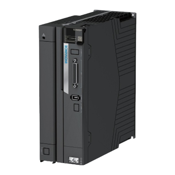
SV630P Series 2.1.2 Components 2.1.2.1 Servo Drives in Size A (Rated Power: 0.2 kW to 0.4 kW) Figure 2-2 Components (SV630PS1R6I, SV630PS2R8I) Table 2–1 Description of components (SV630PS1R6I, SV630PS2R8I) Description Name The 5-digit 8-segment LED display is used to show servo system’s 5-digit LED display ①... -
Page 28: Servo Drives In Size B (Rated Power: 0.75 Kw)
SV630P Series Description Name P⊕ and N⊖ (servo bus Used by the common DC bus for multiple servo drives. terminals) ⑦ P⊕, C (terminals for If an external regenerative resistor is needed, connect it between connecting external terminals P⊕ and C. - Page 29 SV630P Series Table 2–2 Description of components (SV630PS5R5I) Description Name The 5-digit 8-segment LED display is used to show servo system’s running 5-digit LED display ① state and parameter setting. MODE: Used to switch parameters in sequence. △: Used to increase the value of the blinking bit.
-
Page 30: Servo Drives In Size C And D (Rated Power: 1.0 Kw To 3.0 Kw)
SV630P Series 2.1.2.3 Servo Drives in Size C and D (Rated Power: 1.0 kW to 3.0 kW) Figure 2-4 Components (SIZE C:SV630PS7R6I/SIZE D:SV630PS012I) Table 2–3 Description of Components (SIZE C:SV630PS7R6I/SIZE D:SV630PS012I) Description Name The 5-digit 8-segment LED display is used to show servo system’s running 5-digit LED display ①... - Page 31 SV630P Series Description Name CN3, CN4 (communication Connected to RS232 and RS485 host controllers in parallel. ⑩ terminals) CN1 (control terminal) Used by reference input signals and other I/O signals. CN2 (terminal for Connected to the motor encoder terminal. connecting the encoder)
-
Page 32: Servo Drives In Size E (Rated Power: 5.0 Kw To 7.5 Kw)
SV630P Series Description Name ③ CHARGE (bus voltage Indicates the electric charge is present in the bus capacitor. When the indicator turns on, charges possibly still exist in the internal capacitor of indicator) the servo unit, even if the power supply of the main circuit is OFF. - Page 33 SV630P Series Table 2–5 Components (SV630PT017I, SV630PT021I, SV630PT026I) Name Description The 5-digit 8-segment LED display is used to show servo system’s 5-digit LED display ① running state and parameter setting. MODE: Used to switch parameters in sequence. △: Used to increase the value of the blinking bit.
-
Page 34: Product Dimensions
SV630P Series 2.1.3 Product Dimensions Tightening Mass Torque Size Screw Hole Unit: Unit: Unit: mm (in.) kg (lb.) N·m 2-M4 0.6 to 1.2 (1.57) (6.69) (5.91) (1.10) (6.34) (2.95) (1.76) 2-M4 0.6 to 1.2 (1.97) (6.69) (6.81) (1.46) (6.34) (2.95) (2.20) - Page 35 SV630P Series Item Size A Size B Size C Size D 10.1 16.9 23.0 32.0 Max. output current (Arms) 12.8 Continuous input current (Arms) Main circuit power supply Single-phase 200 VAC–240 VAC, -10% to +10%, 50 Hz/60 Hz Main circuit Energy Loss (W)[1] 10.21...
- Page 36 SV630P Series Three-phase 380 V drive ● Item Size C Size D Size E T3R5 T5R4 T8R4 T012 T017 T021 T026 Servo Drive Model Drive Power (kW) Max. applicable motor capacity (kW) 6.05 9.08 10.23 15.15 22.25 25.0 31.25 Power supply equipment capacity (kVA) 11.9...
-
Page 37: Technical Specifications
SV630P Series 2.2.2 Technical Specifications Description Item IGBT PWM control, sine wave current drive mode Control mode 220 V, 380 V: single/three-phase full pulse rectification 18-bit multi-turn absolute encoder, which can be used as an incremental encoder in Encoder feedback absence of the battery 0℃... - Page 38 SV630P Series Description Item Feedforward compensation 0% to 100.0% (resolution: 0.1%) Timing window 1–65535 encoder unit mance Input pulse form Three forms: direction+pulse, phase A + phase B quadrature pulse, CW/ CCW pulse Input form Differential input; open collector Pulse Differential input: single: 4 Mpps, quadrature: 8 Mpps, pulse width ≥...
-
Page 39: Dynamic Brake Characteristics
SV630P Series Description Item Stop at limit switch The servo drive stops immediately when P-OT or N-OT is active Electronic gear ratio 0.001 ≤ B/A ≤ 104857.6 Including protections against overcurrent, overvoltage, undervoltage, overload, main circuit detection error, heatsink overheat, power phase loss, overspeed, encoder error,... -
Page 40: Load Moment Of Inertia
SV630P Series : Maximum feedback speed ● : Dynamic brake program and relay delay ● Load moment of inertia ● : Motor moment of inertia ● : Number of motor pole pairs ● : Stator resistance (Ω) ● : q-axis inductance (mH), d-axis inductance (mH). -
Page 41: Ms1-R Series Motor
MS1-R Series Motor MS1-R Series Motor Product Information 3.1.1 Description of the Model and Nameplate Model Description ① MS1 series servo motor ② Inertia and capacity ③ Rated power (W) H1: low inertia, small capacity One letter and two digits H2: low inertia, medium capacity B: x 10 H3: medium inertia, medium... -
Page 42: Components
MS1-R Series Motor Nameplate description Figure 3-1 Description of the model and nameplate 3.1.2 Components Motor (Flange sizes 40&60&80) Servo motors with terminal box ● Figure 3-2 Components of motors with terminal box (left: front outlet; right: rear outlet) Servo motors with flying leads ●... -
Page 43: Motor Models
MS1-R Series Motor Motor (Flange sizes 100&130&180) Figure 3-4 Components of servo motors in flange sizes 100/130/180 3.1.3 Motor Models Rated speed Rated Output Capacity IP rating of the Motor type (max. speed) Encoder enclosure (kW) (RPM) MS1H1 inertia, 3000 0.05, 0.1, 0.2, 0.4, 0.55, 0.75, 1.0 IP67 T3: 18-bit multi-turn absolute encoder... - Page 44 MS1-R Series Motor Description Item 500 VDC, above 10 MΩ Insulation resistance Permanent magnetic Excitation mode Flange type Installation method Heat resistance level 1500 VAC, 1 min (220 V class) Insulation voltage 1800 VAC, 1 min (380 V class) IP rating of the enclosure IP67 (excluding shaft opening and flying leads type motor connectors) Rotates counterclockwise when viewed from the shaft extension side with the forward run command.
-
Page 45: Overload Characteristics
MS1-R Series Motor Note [1]Vibration level V15 indicates that the vibration amplitude is less than 15 μm when a single servo motor rotates ● at rated values. [2] The resistance for shock in the vertical direction when the servo motor is mounted with the shaft in a ●... - Page 46 MS1-R Series Motor Operating time (s) Load ratio (%) Figure 3-7 MS1H1 and MS1H4 series motor overload curves Note The maximum torque of MS1H1 and MS1H4 models is 3.5 times the rated torque. MS1H2/MS1H3 ● Operating time (s) Load ratio (%) 6000 121.4 2000...
-
Page 47: Derating Characteristics
MS1-R Series Motor Operating time (s) Load ratio (%) 249.4 255.8 262.2 268.6 275.0 281.4 287.8 294.2 Figure 3-8 MS1H2 and MS1H3 series motor overload curves Note The maximum torque of H2 models is three times the rated torque. ● The maximum torque of H3 models is 2.5 times the rated torque. -
Page 48: Temperature Curve Of The Oil Seal
Technical data and torque/speed characteristic values in the following tables are applicable to ■ motors working with Inovance servo drives with the the armature coil temperature being 20°C. Continuous working area: refers to a series of states in which the motor can operate safely and ■... -
Page 49: Low Inertia And Small Capacity (Ms1H1)
● rpm, the motor must run with the key. If you need to run the motor without the key, you can ask for customization from Inovance. Note The data in the () is the value of the servo motor with the brake. -
Page 50: Ms1H1-10B30Cb-T33*Z
MS1-R Series Motor Motor specifications Torque-Speed characteristics Maximum current (Arms) 4.70 Rated speed (rpm) 3000 Maximum speed (rpm) 6000 Torque coefficient (N·m/Arms) 0.15 0.026 Motor without brake Rotor moment of inertia (kg·cm 0.028 Motor with brake Electrical specifications of the motor with brake Supply voltage Holding torque Rated power... - Page 51 MS1-R Series Motor Motor specifications Torque-Speed characteristics Maximum current (Arms) 4.70 Rated speed (rpm) 3000 Maximum speed (rpm) 6000 Torque coefficient (N·m/Arms) 0.26 0.041 Motor without brake Rotor moment of inertia (kg·cm 0.043 Motor with brake Electrical specifications of the motor with brake Supply voltage Holding torque Rated power...
-
Page 52: Ms1H1-20B30Cb-T33*R
MS1-R Series Motor 3.4.3 MS1H1-20B30CB-T33*R Motor specifications Torque-Speed characteristics Flange size (mm) Inertia, capacity Low inertia, small capacity Rated power (kW) Voltage (V) Rated torque (N·m) 0.64 Maximum torque (N·m) 2.24 Heatsink-based derating curve Rated current (Arms) Maximum current (Arms) Rated speed (rpm) 3000 Maximum speed (rpm) -
Page 53: Ms1H1-40B30Cb-T33*R
MS1-R Series Motor 3.4.4 MS1H1-40B30CB-T33*R Motor specifications Torque-Speed characteristics Flange size (mm) Inertia, capacity Low inertia, small capacity Rated power (kW) Voltage (V) 1.27 Rated torque (N·m) Maximum torque (N·m) 4.45 Heatsink-based derating curve Rated current (Arms) Maximum current (Arms) Rated speed (rpm) 3000 Maximum speed (rpm) -
Page 54: Ms1H1-55B30Cb-T331R
MS1-R Series Motor 3.4.5 MS1H1-55B30CB-T331R Motor specifications Torque-Speed characteristics Flange size (mm) Inertia, capacity Low inertia, small capacity Rated power (kW) 0.55 Voltage (V) 1.75 Rated torque (N·m) Maximum torque (N·m) 6.13 Heatsink-based derating curve Rated current (Arms) Maximum current (Arms) Rated speed (rpm) 3000 Maximum speed (rpm) -
Page 55: Ms1H1-75B30Cb-T33*R
MS1-R Series Motor 3.4.6 MS1H1-75B30CB-T33*R Motor specifications Torque-Speed characteristics Flange size (mm) Inertia, capacity Low inertia, small capacity Rated power (kW) 0.75 Voltage (V) 2.39 Rated torque (N·m) Maximum torque (N·m) 8.37 Rated current (Arms) Heatsink-based derating curve Maximum current (Arms) 16.9 Rated speed (rpm) 3000... -
Page 56: Ms1H1-10C30Cb-T33*R
MS1-R Series Motor 3.4.7 MS1H1-10C30CB-T33*R Motor specifications Torque-Speed characteristics Flange size (mm) Inertia, capacity Low inertia, small capacity Rated power (kW) Voltage (V) 3.18 Rated torque (N·m) Maximum torque (N·m) 11.13 Heatsink-based derating curve Rated current (Arms) Maximum current (Arms) Rated speed (rpm) 3000 Maximum speed (rpm) -
Page 57: Low Inertia And Medium Capacity (Ms1H2)
MS1-R Series Motor Low Inertia and Medium Capacity (MS1H2) 3.5.1 MS1H2-10C30CB-T33*R Motor specifications Torque-Speed characteristics Flange size (mm) Inertia, capacity Low inertia, medium capacity Rated power (kW) Voltage (V) 3.18 Rated torque (N·m) Maximum torque (N·m) 9.54 Rated current (Arms) Heatsink-based derating curve Maximum current (Arms) Rated speed (rpm) -
Page 58: Ms1H2-10C30Cd-T33*R
MS1-R Series Motor 3.5.2 MS1H2-10C30CD-T33*R Motor specifications Torque-Speed characteristics Flange size (mm) Inertia, capacity Low inertia, medium capacity Rated power (kW) Voltage (V) 3.18 Rated torque (N·m) Maximum torque (N·m) 9.54 Heatsink-based derating curve Rated current (Arms) Maximum current (Arms) Rated speed (rpm) 3000 Maximum speed (rpm) -
Page 59: Ms1H2-15C30Cb-T33*R
MS1-R Series Motor 3.5.3 MS1H2-15C30CB-T33*R Motor specifications Torque-Speed characteristics Flange size (mm) Inertia, capacity Low inertia, medium capacity Rated power (kW) Voltage (V) Rated torque (N·m) Maximum torque (N·m) 14.7 Heatsink-based derating curve Rated current (Arms) Maximum current (Arms) Rated speed (rpm) 3000 Maximum speed (rpm) 5000... -
Page 60: Ms1H2-15C30Cd-T33*R
MS1-R Series Motor 3.5.4 MS1H2-15C30CD-T33*R Motor specifications Torque-Speed characteristics Flange size (mm) Inertia, capacity Low inertia, medium capacity Rated power (kW) Voltage (V) Rated torque (N·m) Maximum torque (N·m) 14.7 Heatsink-based derating curve Rated current (Arms) Maximum current (Arms) Rated speed (rpm) 3000 Maximum speed (rpm) 5000... -
Page 61: Ms1H2-20C30Cb-T33*R
MS1-R Series Motor 3.5.5 MS1H2-20C30CB-T33*R Motor specifications Torque-Speed characteristics Flange size (mm) Inertia, capacity Low inertia, medium capacity Rated power (kW) Voltage (V) 6.36 Rated torque (N·m) Maximum torque (N·m) 15.5 Heatsink-based derating curve Rated current (Arms) 11.3 Maximum current (Arms) Rated speed (rpm) 3000 Maximum speed (rpm) -
Page 62: Ms1H2-20C30Cd-T33*R
MS1-R Series Motor 3.5.6 MS1H2-20C30CD-T33*R Motor specifications Torque-Speed characteristics Flange size (mm) Inertia, capacity Low inertia, medium capacity Rated power (kW) Voltage (V) 6.36 Rated torque (N·m) Maximum torque (N·m) 19.1 Heatsink-based derating curve Rated current (Arms) Maximum current (Arms) Rated speed (rpm) 3000 Maximum speed (rpm) -
Page 63: Ms1H2-25C30Cb-T33*R
MS1-R Series Motor 3.5.7 MS1H2-25C30CB-T33*R Motor specifications Torque-Speed characteristics Flange size (mm) Inertia, capacity Low inertia, medium capacity Rated power (kW) Voltage (V) 7.96 Rated torque (N·m) Maximum torque (N·m) 23.9 Heatsink-based derating curve Rated current (Arms) 14.7 Maximum current (Arms) Rated speed (rpm) 3000 Maximum speed (rpm) -
Page 64: Ms1H2-25C30Cd-T33*R
MS1-R Series Motor 3.5.8 MS1H2-25C30CD-T33*R Motor specifications Torque-Speed characteristics Flange size (mm) Inertia, capacity Low inertia, medium capacity Rated power (kW) Voltage (V) 7.96 Rated torque (N·m) Maximum torque (N·m) 23.9 Heatsink-based derating curve Rated current (Arms) Maximum current (Arms) Rated speed (rpm) 3000 Maximum speed (rpm) -
Page 65: Ms1H2-30C30Cb-T33*R
MS1-R Series Motor 3.5.9 MS1H2-30C30CB-T33*R Motor specifications Torque-Speed characteristics Flange size (mm) Inertia, capacity Low inertia, medium capacity Rated power (kW) Voltage (V) Rated torque (N·m) Maximum torque (N·m) 24.5 Heatsink-based derating curve Rated current (Arms) 16.6 Maximum current (Arms) Rated speed (rpm) 3000 Maximum speed (rpm) -
Page 66: Ms1H2-30C30Cd-T33*R
MS1-R Series Motor 3.5.10 MS1H2-30C30CD-T33*R Motor specifications Torque-Speed characteristics Flange size (mm) Inertia, capacity Low inertia, medium capacity Rated power (kW) Voltage (V) Rated torque (N·m) Maximum torque (N·m) 29.4 Heatsink-based derating curve Rated current (Arms) Maximum current (Arms) Rated speed (rpm) 3000 Maximum speed (rpm) 6000... -
Page 67: Ms1H2-40C30Cb-T33*R
MS1-R Series Motor 3.5.11 MS1H2-40C30CB-T33*R Motor specifications Torque-Speed characteristics Flange size (mm) Inertia, capacity Low inertia, medium capacity Rated power (kW) Voltage (V) 12.6 Rated torque (N·m) Maximum torque (N·m) 31.5 Heatsink-based derating curve Rated current (Arms) Maximum current (Arms) 67.5 Rated speed (rpm) 3000... -
Page 68: Ms1H2-40C30Cd-T33*R
MS1-R Series Motor 3.5.12 MS1H2-40C30CD-T33*R Motor specifications Torque-Speed characteristics Flange size (mm) Inertia, capacity Low inertia, medium capacity Rated power (kW) Voltage (V) 12.6 Rated torque (N·m) Maximum torque (N·m) 37.8 Heatsink-based derating curve Rated current (Arms) 13.5 Maximum current (Arms) 42.5 Rated speed (rpm) 3000... -
Page 69: Ms1H2-50C30Cb-T33*R
MS1-R Series Motor 3.5.13 MS1H2-50C30CB-T33*R Motor specifications Torque-Speed characteristics Flange size (mm) Inertia, capacity Low inertia, medium capacity Rated power (kW) Voltage (V) 15.8 Rated torque (N·m) Maximum torque (N·m) 39.5 Heatsink-based derating curve Rated current (Arms) Maximum current (Arms) 67.5 Rated speed (rpm) 3000... -
Page 70: Ms1H2-50C30Cd-T33*R
MS1-R Series Motor 3.5.14 MS1H2-50C30CD-T33*R Motor specifications Torque-Speed characteristics Flange size (mm) Inertia, capacity Low inertia, medium capacity Rated power (kW) Voltage (V) 15.8 Rated torque (N·m) Maximum torque (N·m) 47.4 Heatsink-based derating curve Rated current (Arms) Maximum current (Arms) 52.5 Rated speed (rpm) 3000... -
Page 71: Medium Inertia And Medium Capacity (Ms1H3)
MS1-R Series Motor Medium Inertia and Medium Capacity (MS1H3) 3.6.1 MS1H3-85B15CB-T33*R Motor specifications Torque-Speed characteristics Flange size (mm) Inertia, capacity Medium inertia, medium capacity Rated power (kW) 0.85 Voltage (V) 5.39 Rated torque (N·m) Maximum torque (N·m) 13.5 Rated current (Arms) Heatsink-based derating curve Maximum current (Arms) 17.2... -
Page 72: Ms1H3-85B15Cd-T33*R
MS1-R Series Motor 3.6.2 MS1H3-85B15CD-T33*R Motor specifications Torque-Speed characteristics Flange size (mm) Inertia, capacity Medium inertia, medium capacity Rated power (kW) 0.85 Voltage (V) 5.39 Rated torque (N·m) Maximum torque (N·m) 13.5 Heatsink-based derating curve Rated current (Arms) Maximum current (Arms) Rated speed (rpm) 1500 Maximum speed (rpm) -
Page 73: Ms1H3-13C15Cb-T33*R
MS1-R Series Motor 3.6.3 MS1H3-13C15CB-T33*R Motor specifications Torque-Speed characteristics Flange size (mm) Inertia, capacity Medium inertia, medium capacity Rated power (kW) Voltage (V) 8.34 Rated torque (N·m) Maximum torque (N·m) 20.85 Heatsink-based derating curve Rated current (Arms) 10.5 Maximum current (Arms) 27.3 Rated speed (rpm) 1500... -
Page 74: Ms1H3-13C15Cd-T33*R
MS1-R Series Motor 3.6.4 MS1H3-13C15CD-T33*R Motor specifications Torque-Speed characteristics Flange size (mm) Inertia, capacity Medium inertia, medium capacity Rated power (kW) Voltage (V) 8.34 Rated torque (N·m) Maximum torque (N·m) 20.85 Heatsink-based derating curve Rated current (Arms) Maximum current (Arms) 12.6 Rated speed (rpm) 1500... -
Page 75: Ms1H3-18C15Cb-T33*R
MS1-R Series Motor 3.6.5 MS1H3-18C15CB-T33*R Motor specifications Torque-Speed characteristics Flange size (mm) Inertia, capacity Medium inertia, medium capacity Rated power (kW) Voltage (V) 11.5 Rated torque (N·m) Maximum torque (N·m) 28.75 Heatsink-based derating curve Rated current (Arms) 11.9 Maximum current (Arms) 32.2 Rated speed (rpm) 1500... -
Page 76: Ms1H3-18C15Cd-T33*R
MS1-R Series Motor 3.6.6 MS1H3-18C15CD-T33*R Motor specifications Torque-Speed characteristics Flange size (mm) Inertia, capacity Medium inertia, medium capacity Rated power (kW) Voltage (V) 11.5 Rated torque (N·m) Maximum torque (N·m) 28.75 Heatsink-based derating curve Rated current (Arms) 6.75 Maximum current (Arms) 17.7 Rated speed (rpm) 1500... -
Page 77: Ms1H3-29C15Cb-T33*R
MS1-R Series Motor 3.6.7 MS1H3-29C15CB-T33*R Motor specifications Torque-Speed characteristics Flange size (mm) Inertia, capacity Medium inertia, medium capacity Rated power (kW) Voltage (V) 18.6 Rated torque (N·m) Maximum torque (N·m) 46.5 Heatsink-based derating curve Rated current (Arms) Maximum current (Arms) 52.5 Rated speed (rpm) 1500... -
Page 78: Ms1H3-29C15Cd-T33*R
MS1-R Series Motor 3.6.8 MS1H3-29C15CD-T33*R Motor specifications Torque-Speed characteristics Flange size (mm) Inertia, capacity Medium inertia, medium capacity Rated power (kW) Voltage (V) 18.6 Rated torque (N·m) Maximum torque (N·m) 46.5 Heatsink-based derating curve Rated current (Arms) 10.5 Maximum current (Arms) 29.75 Rated speed (rpm) 1500... -
Page 79: Ms1H3-44C15Cb-T33*R
MS1-R Series Motor 3.6.9 MS1H3-44C15CB-T33*R Motor specifications Torque-Speed characteristics Flange size (mm) Inertia, capacity Medium inertia, medium capacity Rated power (kW) Voltage (V) 28.4 Rated torque (N·m) Maximum torque (N·m) 71.1 Heatsink-based derating curve Rated current (Arms) 25.5 Maximum current (Arms) Rated speed (rpm) 1500 Maximum speed (rpm) -
Page 80: Ms1H3-44C15Cd-T33*R
MS1-R Series Motor 3.6.10 MS1H3-44C15CD-T33*R Motor specifications Torque-Speed characteristics Flange size (mm) Inertia, capacity Medium inertia, medium capacity Rated power (kW) Voltage (V) 28.4 Rated torque (N·m) Maximum torque (N·m) 71.1 Heatsink-based derating curve Rated current (Arms) Maximum current (Arms) Rated speed (rpm) 1500 Maximum speed (rpm) -
Page 81: Ms1H3-55C15Cd-T33*R
MS1-R Series Motor 3.6.11 MS1H3-55C15CD-T33*R Motor specifications Torque-Speed characteristics Flange size (mm) Inertia, capacity Medium inertia, medium capacity Rated power (kW) Voltage (V) Rated torque (N·m) Maximum torque (N·m) 87.6 Heatsink-based derating curve Rated current (Arms) 20.7 Maximum current (Arms) Rated speed (rpm) 1500 Maximum speed (rpm) -
Page 82: Ms1H3-75C15Cd-T33*R
MS1-R Series Motor 3.6.12 MS1H3-75C15CD-T33*R Motor specifications Torque-Speed characteristics Flange size (mm) Inertia, capacity Medium inertia, medium capacity Rated power (kW) Voltage (V) Rated torque (N·m) Maximum torque (N·m) Heatsink-based derating curve Rated current (Arms) Maximum current (Arms) Rated speed (rpm) 1500 Maximum speed (rpm) 3000... -
Page 83: Medium Inertia And Small Capacity (Ms1H4)
MS1-R Series Motor Medium Inertia and Small Capacity (MS1H4) 3.7.1 MS1H4-10B30CB-T33*Z Motor specifications Torque-Speed characteristics Flange size (mm) Inertia, capacity Low inertia, small capacity Rated output (kW) Voltage (V) Rated torque (N·m) 0.32 Maximum torque (N·m) 1.12 Rated current (Arms) Heatsink-based derating curve Maximum current (Arms) 4.70... -
Page 84: Ms1H4-20B30Cb-T33*R
MS1-R Series Motor 3.7.2 MS1H4-20B30CB-T33*R Motor specifications Torque-Speed characteristics Flange size (mm) Inertia, capacity Medium inertia, low capacity Rated power (kW) Voltage (V) 0.64 Rated torque (N·m) Maximum torque (N·m) 2.24 Heatsink-based derating curve Rated current (Arms) Maximum current (Arms) Rated speed (rpm) 3000 Maximum speed (rpm) -
Page 85: Ms1H4-40B30Cb-T33*R
MS1-R Series Motor 3.7.3 MS1H4-40B30CB-T33*R Motor specifications Torque-Speed characteristics Flange size (mm) Inertia, capacity Medium inertia, low capacity Rated power (kW) Voltage (V) 1.27 Rated torque (N·m) Maximum torque (N·m) 4.45 Rated current (Arms) Heatsink-based derating curve Maximum current (Arms) Rated speed (rpm) 3000 Maximum speed (rpm) -
Page 86: Ms1H4-55B30Cb-T331R
MS1-R Series Motor 3.7.4 MS1H4-55B30CB-T331R Motor specifications Torque-Speed characteristics Flange size (mm) Inertia, capacity Medium inertia, low capacity Rated power (kW) 0.55 Voltage (V) 1.75 Rated torque (N·m) Maximum torque (N·m) 6.13 Heatsink-based derating curve Rated current (Arms) Maximum current (Arms) 13.2 Rated speed (rpm) 3000... -
Page 87: Ms1H4-75B30Cb-T33*R
MS1-R Series Motor 3.7.5 MS1H4-75B30CB-T33*R Motor specifications Torque-Speed characteristics Flange size (mm) Inertia, capacity Medium inertia, low capacity Rated power (kW) 0.75 Voltage (V) 2.39 Rated torque (N·m) Maximum torque (N·m) 8.37 Heatsink-based derating curve Rated current (Arms) Maximum current (Arms) 16.9 Rated speed (rpm) 3000... -
Page 88: Ms1H4-10C30Cb-T33*R
MS1-R Series Motor 3.7.6 MS1H4-10C30CB-T33*R Motor specifications Torque-Speed characteristics Flange size (mm) Inertia, capacity Medium inertia, low capacity Rated power (kW) Voltage (V) 3.18 Rated torque (N·m) Maximum torque (N·m) 11.13 Heatsink-based derating curve Rated current (Arms) Maximum current (Arms) Rated speed (rpm) 3000 Maximum speed (rpm) -
Page 89: Options
Options Options List of options Type Name Description Installation Applicable AC Position Drive Model To comply with EN 61800-5-1 standards, install a fuse/circuit breaker on the input Fuse and circuit Input side of the side of the servo drive to prevent accidents breaker servo drive caused by short circuit in the internal... -
Page 90: Model Description
Power cables and encoder cables for terminal-type motors must be installed with specialized devices and jigs. Order the finished cables from distributors authorized by Inovance. For more cable information, see "Cable Specifications and Models" in the hardware manual for the servo drive. - Page 91 Options Model of communication cables ① Cable type ② Cable type ③ Cable length (m) S6-L-T: Motion control 00: Servo drive to PC 3.0: 3 m communication cable communication cable 5.0: 5 m S6N-L-T: IS620F motion control 01: Servo drive communication 10.0: 10 m encoder cable (only for servo drive cable (CAN&RS485)
-
Page 92: Cable Selection
Options 4.2.3 Cable Selection Power cable Tolerance L Cable Motor Length Cable Name Cable Model Illustration Model (mm) (mm) Power S6-L-M107-3.0 3000 (-30.30) cable for S6-L-M107-5.0 5000 (-30.50) motor without (-30.80) S6-L-M107-10.0 10000 Front brake outlet (-30.30) S6-L-B107-3.0 3000 (-30.50) S6-L-B107-5.0 5000 Brake... - Page 93 Options Tolerance L Cable Motor Length Cable Name Cable Model Illustration Model (mm) (mm) (-30.30) S6-L-M011-3.0 3000 Power cable for (-30.50) S6-L-M011-5.0 5000 motor without brake MS1H2 (-30.80) S6-L-M011-10.0 10000 motor S6-L-B011-3.0 3000 (-30.30) rated 4 kW/5 kW (-30.50) S6-L-B011-5.0 5000 Brake (-30.80)
- Page 94 Options Encoder cable Tolerance L Cable Motor Length Cable Name Cable Model Illustration Model (mm) (mm) (-30.30) S6-L-P114-3.0 3000 Single-turn (-30.50) S6-L-P114-5.0 5000 absolute encoder (-30.80) S6-L-P114-10.0 10000 cable Front outlet (-30.30) S6-L-P124-3.0 3000 Multi-turn absolute (-30.50) S6-L-P124-5.0 5000 MS1H1/ encoder (-30.80) S6-L-P124-10.0...
- Page 95 Options Communication cables Cable Tolerance Length Cable Name Cable Model Illustration (mm) (mm) Drive-PC (-30.30) S6-L-T00-3.0 3000 communication cable Multi-drive (-10.10) S6-L-T01-0.3 communication cable Servo drive to host S6-L-T02-2.0 2000 (-20.20) controller communication cable Servo drive termination resistor S6-L-T03-0.0 connector Connector Kit Outline Drawing Name...
-
Page 96: Electrical Peripherals
Options Electrical Peripherals 4.3.1 Fuse To prevent accidents caused by short circuit, install a fuse on the input side of the drive. Table 4–1 List of recommended fuses Recommended Fuse Rated Input Drive Model Size Current (A) Rated Current (A) SV630P****I Manufacturer Model... -
Page 97: Breaker
Options 4.3.3 Breaker Table 4–3 Recommended circuit breaker models Rated Input Recommended Circuit Breaker Drive Model Size Current (A) Current (A) SV630P****I Manufacturer Model Single-phase 220 V S1R6 OSMC32N2C4 S2R8 OSMC32N2C6 S5R5 OSMC32N2C16 Schneider S7R6 OSMC32N2C16 S012 12.8 OSMC32N2C20 Three-phase 220 V S7R6 OSMC32N3C10 Schneider... - Page 98 Drive Model Rated Input Current Applicable Reactor Size (mH) SV630P****I T8R4 MD-ACL-10-5-4T T012 MD-ACL-10-5-4T T017 MD-ACL-15-3-4T T021 MD-ACL-40-1.45-4T 1.45 T026 MD-ACL-40-1.45-4T 1.45 Dimensions Inovance input reactors ● Figure 4-1 Dimensions of 10 A to 15 A AC input reactors -97-...
-
Page 99: Emc Filter
Options Figure 4-2 Dimensions of 40 A (1.45 mH) AC input reactors Table 4–5 Dimensions of Inovance AC input reactors (unit: mm) Model MD-ACL-10-5-4T 150±2 85±2 100±2 125±1 Φ7 x 10 MD-ACL-15-3-4T 150±2 85±2 100±2 125±1 Φ7 x 10 MD-ACL-40-1.45-4T Φ7 x 10... - Page 100 Options Table 4–6 Standard EMC filter model and appearance Appearance Filter Model FN 2090 series Schaffner FN3258 series Table 4–7 Filter model selection (Schaffner) Servo drive model Rated Input Current Applicable Filter Size SV630P****I Single-phase 220 V S1R6 FN 2090-3-06 S2R8 FN 2090-4-06 S5R5...
-
Page 101: Magnetic Ring And Magnetic Buckle
Options Figure 4-3 Dimensions of FN 2090 series filters (unit: mm) Table 4–8 Dimensions of FN 2090 series filters (unit: mm) Rated Current (A) 30.3 64.8 49.8 12.3 20.8 19.9 6.3 x 0.8 12.4 32.4 15.5 6.3 x 0.8 113.5±1 57.5±1 45.4±1 94±1... - Page 102 Options In applications with leakage current and signal cable interference, install a magnetic ring or a ferrite clamp. Selection Amorphous magnetic ring: featuring a high permeability within 1 MHz and excellent anti- ● interference performance, but not as low-cost as the ferrite clamp. See for details. “...
-
Page 103: Absolute Encoder Batteries
Options Figure 4-6 Dimensions of the ferrite clamp Table 4–11 Dimensions of the ferrite clamp Size (Length × OD × ID) (mm) Model DYR-130-B 32.0 × 31× 13 Absolute Encoder Batteries Model selection Select an appropriate battery according to the following table. Table 4–12 Description of the absolute encoder battery Battery Rated Values... - Page 104 Options Note [1]: The "standby state" means the encoder counts the multi-turn data by using the power from the external ● battery when the servo drive power supply is not switched on. In this case, data transceiving stops. [2]: During normal operation, the absolute encoder supports one-turn or multi-turn data counting and ●...
-
Page 105: Installation
“ Figure 5–1 ” on page 105 Check whether the product delivered is in good condition. If there is any missing Check whether the product is or damage, contact Inovance or your supplier immediately. intact. Table 5–1 Dimensions of the outer packing box... -
Page 106: Installation Environment
● Altitude Derating is required for altitudes above 1000 m (derate 1% for every additional 100 m). ● For altitudes above 2000 m, contact Inovance. ● Mounting/Operating temperature: 0℃ to 55℃ For temperatures between 0℃ to 45℃, ● derating is not required. For temperatures above 45℃, derate 2% for every additional 1℃. -
Page 107: Installation Clearance
Installation Requirement Item Storage humidity Below 90% RH (no condensation) Below 4.9m/s Vibration During transportation with packing box: compliant with EN 60721-3-2 Class 2M3. ● During installation without packing box: compliant with ISTA 1H. ● Below 19.6m/s Shock IP rating IP20. - Page 108 Installation Figure 5-3 Clearance for side-by-side installation Servo drives rated at 0.2 kW to 0.75 kW (SIZE A and SIZE B) support compact installation, in which a clearance of at least 1 mm (0.04 in.) must be reserved between every two servo drives. When adopting compact installation, derate the load rate to 75%.
-
Page 109: Installation Dimensions
Installation Figure 5-5 Zero-clearance installation 5.1.4 Installation Dimensions Drives in Size A (rated Power: 0.2 kW to 0.4 kW): SV630PS1R6I, SV630PS2R8I Figure 5-6 Dimension drawing of servo drives in size A Drives in Size B (rated Power: 0.75 kW: SV630PS5R5I Figure 5-7 Dimension drawing of servo drives in size B... - Page 110 Installation Servo drives in size C (rated power: 1.0 kW to 1.5 kW): SV630PS7R6I, SV630PT3R5I, and SV630PT5R4I Figure 5-8 Dimension drawing of servo drives in size C Servo drives in size D (rated power: 1.5 kW to 3.0 kW): SV630PS012I, SV630PT8R4I, and SV630PT012I Figure 5-9 Dimension drawing of servo drives in size D Servo drives in size E (rated power: 5.0 kW to 7.5 kW): SV630PT017I, SV630PT021I, and...
-
Page 111: Installation Precautions
Installation 5.1.5 Installation Precautions Table 5–3 Installation Precautions Description Item Install the servo drive vertically and upward to facilitate heat dissipation. For ● installation of multiple servo drives inside the cabinet, install them side by side. For dual-row installation, install an air guide plate. Make sure the servo drive is installed vertically to the wall. -
Page 112: Installation Instructions
Installation Description Item As shown in the figure below, route the servo drive cables downwards to prevent liquid from flowing into the servo drive along the cables. Wiring requirements Insert the dust-proof cover into the communication port (CN3/CN4) not in use. This is to prevent unwanted objects, such as solids or liquids, from falling into the servo drive and resulting in faults. -
Page 113: Installation Of Optional Parts
Installation Figure 5-11 Backplate mounting Note Servo drives in sizes A, B, and C are secured by two screws, with one screw on the top and the other one at the bot- tom. Servo drives in size D are secured by three screws, with two screws on the top and another one at the bottom. Servo drives in size E are secured by four screws, with two screws on the top and the other two at the bottom. -
Page 114: Instructions For Installing The Ac Input Reactor
Installation 5.2.2 Instructions for Installing the AC Input Reactor Figure 5-12 Installing the AC input reactor 5.2.3 Instructions for Installing the EMC Filter Figure 5-13 Installing the AC input reactor 5.2.4 Installation of the Magnetic Ring and Ferrite Clamp Figure 5-14 Installation of the magnetic ring -113-... - Page 115 Installation Figure 5-15 Installation of the ferrite clamp...
-
Page 116: System Wiring Diagram
System Wiring Diagram System Wiring Diagram System Wiring Figure 6-1 Wiring example of a single-phase 220 V system -115-... - Page 117 System Wiring Diagram Figure 6-2 Wiring example of a three-phase 220V system...
-
Page 118: System Composition
System Wiring Diagram Figure 6-3 Wiring example of a three-phase 380 V system Note [1] CN3 and CN4 communication terminals can be used interchangeably. Their pin assignments are exactly the same. System Composition The servo drive is directly connected to an industrial power supply, with no isolation such as a ●... - Page 119 System Wiring Diagram Note The built-in regenerative resistor or jumper bar is not available in models S1R6 and S2R8. If an external ● regenerative resistor is needed for these models, connect it between terminals P⊕ and C. Remove the jumper between P⊕ and D before using the external regenerative resistor. Failure to comply will ●...
-
Page 120: 电气接线图
电气接线图 电气接线图 Wiring diagram of the Position Control Mode S-RDY+(DO1+) 6 S-RDY-(DO1-) COIN+(DO2+) COM+ 4 COIN-(DO2-) 4.7k P-OT(DI1) BK+(DO3+) 4.7k N-OT(DI2) 10 2 BK-(DO3-) 4.7k INHIBIT(DI3) 34 ALM+(DO4+) 26 ALM-(DO4-) 4.7k ALM-RST(DI4) 8 HomeAttain+(DO5+) 4.7k S-ON(DI5) 33 27 HomeAttain-(DO5-) HomeSwitch(DI8) 30 4.7k Undefined(DI9) 4.7k... -
Page 121: Wiring Diagram For Torque Control Mode
电气接线图 Wiring Diagram for Torque Control Mode Figure 7-2 Wiring Diagram for Torque Control Mode Note [1] The range of the internal +24 V power supply is 20 V to 28 V, with maximum operating current being 200 mA. ● [2] DI8 and DI9 are high-speed DIs that must be used according to their functions assigned. -
Page 122: Wiring Terminals
Wiring Terminals Wiring Terminals Wiring Precautions Read through the safety instructions in Chapter "Fundamental Safety Instructions". Failure to comply may result in serious consequences. Do not use the power from IT system for the servo drive. Use the power from TN/TT system for the drive. Failure ●... - Page 123 Wiring Terminals The specification and installation of external cables must comply with applicable local regulations. ● Observe the following requirements when the servo drive is used on a vertical axis. ● Set the safety device properly to prevent the workpiece from falling upon warning or overtravel. ●...
- Page 124 Wiring Terminals Size A (rated power: 0.2 kW–0.4 kW): SV630PS1R6I, SV630PS2R8I Figure 8-1 Terminal pin layout of servo drives in size A Rated power: (SIZE B: 0.75 kW): SV630PS5R5I Figure 8-2 Terminal pin layout of servo drives in size B -123-...
- Page 125 Wiring Terminals Servo drives in size C and size D (rated power: 1.0 kW to 1.5 kW): size C: SV630PS7R6I; size D: SV630PS012I Figure 8-3 Terminal pin layout of servo drives in size C (SV630PS7R6I) and size D (SV630PS012I)
- Page 126 Wiring Terminals Servo drives in size C and size D (rated power: 1.0 kW to 3.0 kW): size C: SV630PT3R5I and SV630PT5R4I; size D: SV630PT8R4I and SV630PT012I Figure 8-4 Terminal pin layout of servo drives in size C (SV630PT3R5I, SV630PT5R4I) and size D (SV630PT8R4I, SV630PT012I) -125-...
-
Page 127: Main Circuit Terminals
Wiring Terminals Size E (rated power: 5.0 kW to 7.5 kW): SV630PT017I, SV630PT021I, and SV630PT026I Figure 8-5 Terminal pin layout of servo drives in size E Main Circuit Terminals 8.2.1 Wiring Precautions Do not connect the input power supply cables to the output terminals U, V, and W. Failure to ●... -
Page 128: Main Circuit Wiring Requirements
Wiring Terminals The servo drive carries a capacitor in the power supply part, and this capacitor will be charged with a high current for 0.2s upon power-on. Turning on/off the power supply frequently affects the performance of main circuit components inside the servo drive. Use a grounding cable with the same cross-sectional area as the main circuit cable. -
Page 129: Recommended Cable Specifications And Models
Wiring Terminals 8.2.3 Recommended Cable Specifications and Models Table 8–1 Input/Output current specifications of the servo drive Rated input current (A) Rated output current (A) Maximum Output Current (A) Drive model SV630P****I Single-phase 220V S1R6 Size A S2R8 10.1 Size B S5R5 16.9 Size C... - Page 130 Wiring Terminals L1C, L2C P⊕, D, C, NΘ, N2, N1 U, V, W, PE Grounding terminal L1, L2, L3/R, S, T Drive model SV630P****I Rated input Size Model current (A) T8R4 2 x 0.82 3 x 1.31 2 x 1.31 3 x 1.31 2.08 Size D...
- Page 131 Wiring Terminals Table 8–4 Main circuit cable lug and tightening torque Recommended PVC Cable Model (at 40℃) Servo drive model SV630P****I Rated Input Tightening Torque U, V, W, PE Cable Grounding Cable Current Brake Cable Lug SIZE Model (N·m) Single-phase 220V S1R6 TVR2-4 Size A...
- Page 132 Wiring Terminals Servo drive model SV630P****I Terminal Block T017 Size E T021 T026 Table 8–7 Specifications of motor output cables MS1H1/H4 05B–10C (applicable to 0.05 kW–1 kW) Cable type Regular cable Flexible cable Oil-resistant shielded flexible cable S6-L-M/B***-X.X S6-L-M/B***-X.X-T S6-L-M/B***-X.X-TS Cable model UL2517 (rated temperature: 105℃) UL2517 (rated temperature: 105℃)
- Page 133 Wiring Terminals MS1H2 10C–50C (Applicable to 1 kW–5 kW)/MS1H3 85B–18C (Applicable to 850 W–1.8 kW) Internal structure and conductor colors Fill in "X.X" in the model number with cable length. Table 8–9 Specifications of motor output cables MS1H3 29C–75C (Applicable to 2.9 kW–7.5 kW) Cable type Regular cable Flexible cable...
-
Page 134: Main Circuit Terminal Layout
● ambient temperature exceeds 40℃). Note If the recommended cable specifications for peripheral devices or optional parts exceed the applicable cable specifi- cation range, contact Inovance. 8.2.4 Main circuit terminal layout Size A (rated power: 0.2 kW–0.4 kW): SV630PS1R6I, SV630PS2R8I... - Page 135 Wiring Terminals Table 8–10 Description of main circuit terminal pins of servo drives in size A Description Parameter Name L1, L2 See the nameplate for the rated voltage class. (power input terminals) P⊕, NΘ Used by the common DC bus for multiple servo drives. (DC bus terminals) P⊕, C If an external regenerative resistor is needed, connect it between...
- Page 136 Wiring Terminals Description Parameter Name U, V, W Connected to U, V, and W phases of the servo motor. (terminals for connecting the servo motor) Connected to the grounding terminal of the motor for grounding Motor grounding purpose. terminal Rated power (SIZE C/SIZE D: 1.0kW–1.5kW): SV630PS7R6I, SV630PS012I Figure 8-10 Main circuit terminal pin layout of servo drives in size C (SV630PS7R6I) and size D (SV630PS012I) Table 8–12 Description of main circuit terminal pins of servo drives in size C (SV630PS7R6I) and size D...
- Page 137 Wiring Terminals Servo drives in size C and size D (rated power: 1.0 kW to 3.0 kW): SV630PT3R5I, SV630PT5R4I, SV630PT8R4I, and SV630PT012I Figure 8-11 Main circuit terminal pin layout of servo drives in size C (SV630PT3R5I, SV630PT5R4I) and size D (SV630PT8R4I, SV630PT012I) Table 8–13 Description of main circuit terminal pins of servo drives in size C (SV630PT3R5I, SV630PT5R4I) and size D (SV630PT8R4I, SV630PT012I) Description...
-
Page 138: Connecting The Motor (Uvw)
Wiring Terminals Size E (rated power: 5.0 kW to 7.5 kW): SV630PT017I, SV630PT021I, and SV630PT026I Figure 8-12 Pin assignment of main circuit terminal of servo drives in size E Table 8–14 Description of main circuit terminal pins of servo drives in size E Description Parameter Name L1C, L2C... - Page 139 Note [1] The flange size refers to the width of the mounting flange (in mm). ● Power cable colors are subject to the actual product. All cable colors mentioned in this guide refer to Inovance ● cable colors. The connection diagram for a flying leads type motor is shown in the following figure.
- Page 140 Note [1]: The flange size refers to the width of the mounting flange. ● Power cable colors are subject to the actual product. All cable colors mentioned in this guide refer to Inovance ● cable colors. The following table describes the connector for high-power motor power cables.
-
Page 141: Wiring Of External Emc Filter
Note [1]: The flange size refers to the width of the mounting flange. ● Power cable colors are subject to the actual product. All cable colors mentioned in this guide refer to Inovance ● cable colors. 8.2.6 Wiring of External EMC Filter Install the filter near the input terminals of the drive. - Page 142 Wiring Terminals Figure 8-17 Main circuit wiring Note 1KM: Electromagnetic contactor; 1Ry: Relay; 1D: Flywheel diode ● DO is set as alarm output (ALM+/-). When the servo drive alarms, the power supply will be cut off automatically. ● SV630PS1R6I and SV630PS2R8I are not configured with built-in regenerative resistors, if the regenerative resistor is needed, connect an external regenerative resistor between P⊕...
- Page 143 Wiring Terminals Figure 8-18 Main circuit wiring of three-phase 220 V models Note 1KM: Electromagnetic contactor; 1Ry: Relay; 1D: Flywheel diode ● The DO is set as alarm output (ALM+/-). When the servo drive alarms, the power supply is cut off automatically ●...
-
Page 144: Grounding And Wiring
Wiring Terminals Figure 8-19 Main circuit wiring of three-phase 380V models Note 1KM: Electromagnetic contactor; 1Ry: Relay; 1D: Flywheel diode ● The DO is set as alarm output (ALM+/-). When the servo drive alarms, the power supply is cut off automatically ●... - Page 145 Wiring Terminals For use of multiple servo drives, observe all the grounding instructions for the drive. Improper grounding of the ● device will lead to malfunction of the drive and the device. Do not share the same grounding cable with other devices (such as welding machines or high-current electrical ●...
- Page 146 Wiring Terminals Description Connect the PE cable on the input power supply side to the input PE terminal of the servo ⑤ drive. ⑥ Ground the motor enclosure. Three-phase motor ⑦ Note The main circuit terminal layout varies with different models and is subject to the physical product. Multi-drive grounding Side-by-side installation of multiple drives: Table 8–20 Description for grounding of multiple drives installed side by side...
-
Page 147: Description Of Control Terminal (Cn1)
Wiring Terminals Table 8–21 Wiring requirements Wiring requirements Place the control unit and the drive unit in two separate control cabinets. If multiple control cabinets are used, connect the control cabinets by using a PE cable with a cross-sectional area of at least 16 mm for equipotentiality between the control cabinets. -
Page 148: Terminal Layout
Wiring Terminals Control Cable Specifications Table 8–22 Recommended Control Cable Specifications Connector Kit/Material No. Control terminal DB44 24 to 30 I/O signal layout I/O signals include DI/DO signals and relay output signals. Observe the following requirement during control circuit wiring: Route the control circuit cables and main circuit cables or other power cables through different routes with a distance of at least 30 cm. - Page 149 Wiring Terminals Figure 8-23 Control terminal pin layout of servo drives in sizes C, D, and E Note CN1: Plastic housing of plug on cable side: DB25P (manufacturer: SZTDK), black housing. Core: HDB44P male ● solder (manufacturer: SZTDK). Use shielded cables as signal cables, with both ends of the shielded cable grounded. ●...
-
Page 150: Position Reference Input Signals
Wiring Terminals Table 8–24 Description of DI/DO signals Signal Name Default Function Pin No. Function P-OT Positive limit switch Negative limit switch N-OT Pulse input forbidden INHIBIT Alarm reset (edge-triggered) ALM-RST S-ON Servo ON HomeSwitch Home switch Reserved +24V Internal 24 V power supply, voltage range: 20 to 28 V, maximum output COM–... - Page 151 Wiring Terminals Table 8–26 Correspondence between pulse input frequency and pulse width Minimum Pulse Max. Frequency (pps) Voltage (V) Pulse Mode Width (us) > 3.0 Differential 200k Low speed Open-collector 200k High-speed differential 0.125 > 3.0 Note You can either use high-speed pulses or low-speed pulses, but not both of them together. ●...
- Page 152 Wiring Terminals Figure 8-24 Correct: The internal 24 V power supply of the servo drive is used. Figure 8-25 Incorrect: Pin 14 (COM–) is not connected, leading to failure in forming a closed-loop circuit. When the external power supply is used: -151-...
- Page 153 Wiring Terminals Scheme 1: Using the built-in resistor (recommended) ■ Scheme 2: Using the external resistor ■...
- Page 154 Wiring Terminals Select resistor R1 based on the following formula. Table 8–27 Recommended resistance of R1 Voltage (V) R1 Resistance (kΩ) R1 Power (W) The following figures show examples of improper wiring. ■ 1: The current limiting resistor is not connected, resulting in terminal burnout. ■...
- Page 155 Wiring Terminals 2: Multiple terminals share the same current limiting resistor, resulting in pulse receiving error. ■ Figure 8-27 Incorrect wiring example 2: Multiple terminals share the same current limiting resis- tor, resulting in pulse receiving error. Incorrect wiring 3: The SIGN port is not connected, preventing these two ports from receiving ■...
- Page 156 Wiring Terminals Figure 8-29 Incorrect wiring example 4: Terminals are connected incorrectly, resulting in terminal burnout. Wrong wiring 5: Multiple terminals share the same current limiting resistor, resulting in pulse ■ receiving error. Figure 8-30 Incorrect wiring example 5: Multiple terminals share one current limiting resistor, re- sulting in a pulse receiving error.
-
Page 157: Di/Do Signals
Wiring Terminals Note This is a 5 V system. Do not input 24 V power. ● Some models comes with a detection feature on HSIGN+ and HSIGN- to detect if HSIGN+ is connected to 24 V, ● HSIGN- is connected to external 0 V, but no current limit resistor is connected. When this case is detected, the drive issues an E991.1 warning. - Page 158 Wiring Terminals When you use an external power supply: ■ The host controller provides open-collector output. ● When you use the internal 24 V power supply: ■ -157-...
- Page 159 Wiring Terminals When you use an external power supply: ■ Note PNP and NPN input cannot be used together in the same circuit. DO circuit The circuits for DO1 to DO5 are the same. The following description takes DO1 circuit as an example. The host controller provides relay input.
-
Page 160: Encoder Frequency-Division Output Signals
Wiring Terminals The host controller provides optocoupler input: ● Note The maximum permissible voltage and current capacity of the optocoupler output circuit inside the servo drive are as follows: Maximum voltage: 30 VDC ● Maximum current: DC 50 mA ● 8.3.4 Encoder Frequency-Division Output Signals For details on encoder frequency-division output signals, see... - Page 161 Wiring Terminals Figure 8-31 Differential receiving circuit Figure 8-32 Optocoupler receiving circuit Encoder phase Z output circuit outputs OC signals. Typically, this circuit provides feedback signals to the host controller in a position control system. An optocoupler circuit, relay circuit, or bus receiver circuit shall be used in the host controller to receive feedback signals.
-
Page 162: Wiring Of The Brake
When deciding the length of the motor brake cable, take the voltage drop caused by cable resistance into consideration. The input voltage must be at least 21.6 V to enable the brake to work properly. The following table lists brake specifications of Inovance MS1 series servo motors. -161-... -
Page 163: Encoder Terminal Cn2
Wiring Terminals Table 8–28 Brake specifications Supply Voltage Holding Torque Coil Resistance Exciting Current Release Time Apply Time Backlash Motor Model (VDC) (N·m) (Ω)±7% (ms) (ms) (°) ±10% MS1H1-05B/10B 0.32 94.4 0.25 ≤ 20 ≤ 40 ≤ 1.5 MS1H4-10B MS1H1-20B/40B 75.79 0.32 ≤... -
Page 164: Connecting The Absolute Encoder
The encoder cable color is subject to the color of the actual product. Cable colors mentioned in this guide all ● refer to Inovance cables. The following figure describes the lead wire color of the battery box. Figure 8-37 Lead wire color of the battery box... - Page 165 Wiring Terminals Table 8–30 Terminal-type motor encoder cable connector Motor Frame Illustration Signal Name Type Size Pin No. Color Twisted pair Orange Blue Servo Twisted pair drive Purple side Terminal-type: 6-pin male (right side as the Enclosure connecting side) Blue Twisted pair Purple Brown...
-
Page 166: Installing Absolute Encoder Battery Box
Wiring Terminals Table 8–32 Absolute encoder cable connector (MIL-DTL-5015 series 3108E20-29S aviation connector) Motor Frame Illustration Signal Type Pin No. Color Size Name Twisted pair Orange Blue Twisted Servo drive pair Purple side 6-pin male (right side as Enclosure the connecting side) Blue Twisted pair... - Page 167 Wiring Terminals Installing the battery box Figure 8-38 Installing the battery box (bottom view) Removing the battery box The battery may generate leakage liquid after long-term use. Replace it every two years. Remove the battery box in steps shown in the preceding figure, but in the reverse order. When closing the battery box cover, prevent the connector cable from being pinched.
-
Page 168: Encoder Cable Specifications
0.52 33.9 42.2 7.6±0.3 3P×19AWG 0.57 26.9 53.2 8.5±0.3 3P×18AWG 0.81 21.4 66.8 8.8±0.3 3P×17AWG 1.03 16.3 87.7 9.7±0.3 3P×16AWG 1.31 13.5 105.0 11.4±0.3 Note If the cables of above 16AWG are required, contact the sales personnel of Inovance. -167-... -
Page 169: Communication Terminals Cn3 And Cn4
Wiring Terminals Communication Terminals CN3 and CN4 Terminal Layout Figure 8-39 Communication Terminal pin layout of the servo drive Table 8–34 Description of communication terminal pins Description Description Pin No. CANH CAN communication port CANL CAN communication ground CGND RS485+ RS485 communication port RS485- RS232 transmitting end, connected to the receiving end of... - Page 170 Wiring Terminals CN3 and CN4 in the drive are used for communication with the PC, PLC, and other drives. For pin “ Figure 8–39 Communication Terminal pin layout of the servo drive ” on assignment of CN3/CN4, see page 168 RS485 communication with PLC The following figure shows the cable used for 485 communication between the servo drive and PLC.
- Page 171 Wiring Terminals In case of a large number of nodes, use the daisy chain mode for RS485 communication. Connect the reference grounds of RS485 signals of all the nodes (up to 128 nodes) together. Figure 8-43 RS485 bus topology Do not connect (GND) terminal to the CGND terminal of the drive.
- Page 172 Wiring Terminals Table 8–38 Pin connection relation between the servo drive and PC communication cable RJ45 on the Drive Side (A) DB9 on the PC Side (B) Signal Name Signal Name Pin No. Pin No. RS232-TXD PC-RXD RS232-RXD PC-TXD PE (shield layer) Enclosure PE (shield layer) Enclosure...
-
Page 173: Wiring And Setting Of The Regenerative Resistor
Wiring Terminals Wiring and Setting of the Regenerative Resistor Connecting the regenerative resistor Figure 8-47 Wiring of external regenerative resistor “ 8.2.3 Recommended Cable Specifications and Models ” on For cables used for terminals P⊕ and C, see page 128 Observe the following precautions when connecting the external regenerative resistor: The built-in regenerative resistor or jumper bar is not available in models S1R6 and S2R8. -
Page 174: Commissioning Tool
Commissioning Tool Commissioning Tool Operating Panel 9.1.1 Display Panel Components Figure 9-1 Magnified view of the keypad The operation panel of the SV630 Series servo drive consists of an LED (5-digit, 8-segment) and five buttons. The keypad is used for value display, parameter setting, user password setting and general function execution. - Page 175 Commissioning Tool Display mode switchover Figure 9-2 Switchover among different display modes The keypad enters status display immediately upon power-on. ● Press MODE to switch among different display modes based on the conditions shown in “ Figure 9– ● 2 ” on page 174 In status display, set H02.32 to select the parameter to be monitored.
- Page 176 Commissioning Tool Parameter Display Parameters are divided into 19 groups based on their functions. A parameter can be located quickly based on the parameter group it belongs to. For details on parameters, see Chapter "Parameter List". Display of parameter groups ●...
- Page 177 Commissioning Tool Figure 9-4 Display of "1073741824" Display of the decimal point ● The segment "." of the ones indicates the decimal point, which does not blink. Display Description Parameter Name Decimal point 100.0 Display of parameter setting status ● Display Applicable Occasion Meaning...
-
Page 178: Parameter Settings
Commissioning Tool Note If the panel displays Hault/Fault, a system fault has occurred. ● The possible causes include bugs of the program, external interference like static electricity or electromagnetic ● interference, extreme operating temperature or radiation. In this case, record the values of H16.00–H16.27, and consult with our R&D engineers. ●... - Page 179 Commissioning Tool Figure 9-5 Example of parameter setting MODE: Used to switch the keypad display mode and return to the previous interface. ● UP/DOWN: Used to increase or decrease the value of the blinking digit. ● SHIFT: Used to shift the blinking digit. ●...
- Page 180 Commissioning Tool Figure 9-6 Procedure for setting forced DI function H0d.18 is used to set the forced DI input. The keypad displays the value in hexadecimal. After the hexadecimal value is converted to a binary value, the value "1" indicates high level and "0" indicates low level.
- Page 181 Commissioning Tool Monitoring the DI level status through H0b.03: If the DI function is normal, the display value of H0b.03 is always the same as that of H0d.18. In this case, the DI1 is active low, DI2 to DI9 are active high and the value of H0b.03 read by the software tool is 414 (in decimal).
- Page 182 Commissioning Tool Figure 9-9 Procedure for setting forced DO function H0d.19 (Forced DO value) is used to set whether the DO function is active. The keypad displays the value in hexadecimal. After the hexadecimal value is converted to a binary value, the value "1" indicates the DO function is active and "0"...
- Page 183 Commissioning Tool Figure 9-10 Meaning of the H0d.19 setpoint Monitoring the DO level status through H0b.05: If the logic of all the three DO terminals are "active at low level", the DO1 terminal is high level and DO2 to DO5 terminals are low level, and the corresponding binary number is "00001". In this case, the value of H0b.05 (Monitored DO signal) read by the software tool is 1 (decimal).
-
Page 184: Commissioning Software
InoDriverShop, see the help document of InoDriverShop. 9.2.2 To install the fan, do as follows: 1. Software a. Visit the official website of Inovance as shown below. http://www.inovance.com b. Choose Support → Download, and then type in the keyword InoDriverShop and click Search. -183-... - Page 185 InoDriverShop. 4. Click Next. 5. You can select the directory for installation as needed through the Browse button. The default directory for installation is "C:\Program Files\Inovance\InoDriverShop". In online upgrade, InoDriverShop will be upgraded directly in the original directory.
- Page 186 Commissioning Tool After selecting the directory for installation, click Next. 6. Click Install to start installation. -185-...
- Page 187 Commissioning Tool 7. After installation is done, click Finish. 8. A shortcut icon for InoDriverShop will be generated automatically on the desktop.
-
Page 188: Connection
Commissioning Tool 9.2.3 Connection 1. Start InoDriverShop. Double-click to start the InoDriverShop. ● If there is no shortcut for InoDriverShop on your desktop, click Start and search for ● InoDriverShop. 2. Create a project. a. Click ① shown in the following figure to create a project. Figure 9-14 Start interface Note You can click 2 or 3 shown in the preceding figure to open the project saved before. - Page 189 Commissioning Tool Figure 9-15 Project Guide interface c. Click Next page to create a project. Creating a project for online device brings you to the following interface. The device is scanned ● automatically. Select the device to be commissioned and click Finish. Figure 9-16 Scan interface Creating a project for offline device brings you to the following interface.
-
Page 190: Introduction To The Software Tool
Commissioning Tool Figure 9-17 Project Guide interface for offline device Note ① Station No., ④ Project name, and the storage directory can be changed as needed. d. The project has been created. 3. The main interface is shown as follows. Figure 9-18 Main interface 9.2.4 Introduction to the Software Tool... - Page 191 Commissioning Tool Parameter management: Reads and downloads parameters in batches. ● Inertia auto-tuning: Generates the load inertia ratio automatically. ●...
- Page 192 Commissioning Tool Mechanical characteristic analysis: Analyzes the resonance frequency of the mechanical system. ● Motion JOG: Generates position references to make the motor reciprocate. ● Gain tuning: Adjusts the stiffness level and monitors the motion data. ● -191-...
-
Page 193: Commissioning And Operation
Commissioning and Operation Commissioning and Operation 10.1 Commissioning Flowchart Figure 10-1 Commissioning flowchart of the drive 10.2 Inspection Before Commissioning Check the following items before commissioning the servo drive and the servo motor. Table 10–1 Checklist Description Wiring The power input terminals (L1, L2/L1, L2, L3/L1C, L2C/R, S, T) of the servo drive □... -
Page 194: Power-On
Commissioning and Operation Description The signal cables of the servo drive are connected correctly. The external signal cables such as the brake cable and the overtravel protection cable are □ connected reliably. The servo drive and servo motor are grounded properly. □... -
Page 195: Jog
Commissioning and Operation 10.4 To use the jog function, deactivate the S-ON signal first. The jog function can be used in trial run to check whether the motor rotates properly, without abnormal vibration or noise generated during rotation. You can activate the jogging function through the keypad, two pre-configured external DIs, or the software tool. - Page 196 Commissioning and Operation Procedure: ● 1. Enter the jog mode by setting H0d.11 through the keypad. The keypad displays the default jog speed at this moment. 2. Adjust the jog speed through the UP/DOWN key and press the SET key to enter the jog state. The keypad displays "JOG".
-
Page 197: Setting Parameters
Commissioning and Operation 10.5 Setting Parameters Rotation direction selection Set H02.02 to change the direction of rotation directly. ☆ Related parameters: Change Page Param. Name Value Default Unit Mode H02.02 At stop H02_en.02 2002-03h Forward direction 0: Counterclockwise (CCW) as “... - Page 198 Commissioning and Operation The direction of "forward drive" in overtravel prevention is the same as that defined by H02.02. Brake setting The brake is used to prevent the motor shaft from moving and lock the position of the motor and the motion part when the drive is in the non-operational status.
- Page 199 Commissioning and Operation Note Do not use a holding brake for braking. ● The release time and operation time of the brake depend on the discharge circuit. Be sure to confirm the ● operation delay of your equipment before use. You need to prepare the 24 VDC power supply yourself.
- Page 200 Commissioning and Operation Figure 10-4 Brake sequence for motor at standstill Note [1]: When the S-ON signal is switched on, the brake output is set to "ON" at a delay of about 100 ms, with motor ● being energized at the same time. “...
- Page 201 Commissioning and Operation When the S-ON signal is switched on, do not input a position/speed/torque reference within the time defined by ● H02.09. Otherwise, reference loss or an operation error may occur. If the S-ON signal is switched off when the motor is still rotating, the motor enters the "Stop at zero speed" state, ●...
- Page 202 Commissioning and Operation Change Page Param. Name Value Default Unit Mode H02_en.11 H02.11 2002-0Ch Motor speed 0 RPM to 3000 RPM Real-time “ ” threshold at brake on page 396 output OFF in rotation state H02_en.12 H02.12 2002-0Dh Delay from S-ON 1ms to 1000ms Real-time “...
- Page 203 Commissioning and Operation Table 10–3 Specifications of the regenerative resistor Specifications of Built-in Regenerative Resistor External regenerative resistor Min. Allowable Servo Drive Model Processing Power Resistance (Ω) Power (Pr) (W) Resistance (Ω) (Pa) (W) (H02.21) SV630PS1R6I SV630PS2R8I SV630PS5R5I SV630PS7R6I SV630PS012I SV630PT3R5I SV630PT5R4I SV630PT8R4I...
- Page 204 Commissioning and Operation Regenerative Energy Can Be Drive Model Remarks Absorbed SV630PS1R6I 13.15 The input voltage of the main circuit power supply is 220 VAC. SV630PS2R8I 26.29 The following table shows the energy generated by a 220 V motor in decelerating from the rated ■...
- Page 205 Commissioning and Operation EO Generated Rotor Inertia Servo Motor Model Max. Braking Energy Capacity (kW) During Decelerating from Absorbed by Capacitor E J (10 MS1H*-*******-***** Rated Speed to a Standstill (J) 1.46 7.22 MS1H4-75B30CB-T331R 0.75 22.39 (1.51) (7.47) MS1H4-75B30CB-T334R 1.87 9.25 MS1H4-10C30CB-T331R 32.39...
- Page 206 Commissioning and Operation Note Values inside the parentheses "()" are for the motor with a brake. Note If the total braking time T is known, you can determine whether an external regenerative resistor is needed and the power required using the following flowchart and formula. Regenerative resistor selection ●...
- Page 207 Commissioning and Operation Change Page Param. Name Value Default Unit Mode H02_en.25 H02.25 2002-1Ah Regenerative 0: Built-in At stop “ ” resistor type 1: External, natural ventilated on page 399 2: External, forced air cooling 3: Not needed Take the H1 series 750 W model as an example. Assume that the reciprocating cycle (T) is 2s, the maximum speed is 3000 RPM, and the load inertia is (4 x Motor inertia), then the required power of the braking resistor is as follows: The calculated result is smaller than the processing capacity (Pa = 40 W) of the built-in regenerative...
- Page 208 Commissioning and Operation by the servo drive. Remove the jumper bar between terminals P⊕ and D, and connect the external regenerative resistor between terminals P⊕ and C. For the wiring diagram and lead wire specifications of the external regenerative resistor, see “...
-
Page 209: Trial Run
Commissioning and Operation When E < E , the regenerative resistor is not needed because the braking energy can be absorbed by the bus capacitor. In this case, set H02.25 to 3. External load torque applied, motor in generating state ●... - Page 210 Commissioning and Operation Description If the motor rotates in the correct direction, you can view the actual speed in □ H0b.00 and the average load rate in H0b.12 through the keypad or the software tool. After checking preceding conditions, adjust related parameters to make the □...
- Page 211 Commissioning and Operation Figure 10-10 Sequence of "Coast to stop, keeping de-energized state" at No. 1 fault Note [1] When FunOUT.9 (BK, brake output) is not used, H02.11 and H02.12 are invalid. ● [2] For the delay of brake contactor actions, see for details. “...
- Page 212 Commissioning and Operation Figure 10-12 Sequence of "Dynamic braking stop, keeping dynamic braking state" at No. 1 fault Note [1] When FunOUT.9 (BK, brake output) is not used, H02.11 and H02.12 are invalid. ● “ Table 10–2 ” on page 197 [2] For the delay of brake contactor actions, see for details.
- Page 213 Commissioning and Operation Figure 10-14 Sequence of "Stop at zero speed, keeping de-energized state" at No. 2 fault (without brake) No. 2 fault (without brake): Stop at zero speed, keeping dynamic braking state ● Figure 10-15 Sequence of "Stop at zero speed, keeping dynamic braking state" at No. 2 fault (with- out brake) No.
- Page 214 Commissioning and Operation Figure 10-16 Sequence of "Dynamic braking stop, keeping dynamic braking state" at No. 2 fault (without brake) No. 2 fault (without brake): Dynamic braking stop, keeping de-energized state ● Figure 10-17 Sequence of "Dynamic braking stop, keeping de-energized state" at No. 2 fault (with- out brake) No.
- Page 215 Commissioning and Operation Figure 10-18 Sequence of "Stop at zero speed, keeping dynamic braking state" at No. 2 fault (with brake) Note [1] When FunOUT.9 (BK, brake output) is not used, H02.10 is invalid. ● [2] For the delay of brake contactor actions, see for details. “...
- Page 216 Commissioning and Operation Figure 10-19 Sequence for warnings that cause stop The other warnings do not affect the operation state of the drive. The sequence diagram for these warnings is shown in “ Figure 10–20 Sequence for warnings that do not cause stop ” on page 215 Warnings that do not cause stop ●...
-
Page 217: Servo Off
Commissioning and Operation Figure 10-21 Sequence for fault reset Note [1] The DI signal used for fault reset (FunIN.2: ALM-RST) is edge triggered. ● [2] For the delay of brake contactor actions, see for details. “ Table 10–2 ” on page 197 ●... - Page 218 Commissioning and Operation The stop causes can be divided into the following types: stop at S-ON OFF, stop at fault, stop at overtravel, and emergency stop. See the following descriptions for details. Stop at S-ON OFF Assign the S-ON function to a certain DI and deactivate the logic of this DI. ☆...
- Page 219 Commissioning and Operation Stop at overtravel ★ Definition of terms: "Overtravel": The mechanical motion exceeds the designed range of safe movement. ● Stop at overtravel: When a motion part moves beyond the range of safe movement, the limit switch ● outputs a level change signal, and the servo drive forcibly stops the motor.
- Page 220 Commissioning and Operation Emergency stop The servo drive supports two emergency stop modes: Using DI function 34: FunIN.34 (EmergencyStop) ● Using the auxiliary function: emergency stop (H0d.05) ● ☆ Related parameters: Parameter Function Name Function Code Name Inactive: Current operating state unaffected Emergency- Active: Stop quickly as defined by H02.18, keeping Braking...
-
Page 221: Adjustment
Adjustment Adjustment 11.1 Overview The servo drive must drive the motor as quick and accurate as possible to follow the commands from the host controller or internal setting. Gain adjustment needs to be performed to meet such requirement. Figure 11-1 Example of gain tuning Position loop gain: 40.0 Hz Position loop gain: 200.0Hz Position loop gain: 200.0Hz... - Page 222 Adjustment Figure 11-2 Steps Table 11–1 Description of gain tuning Steps Function Reference Offline “ 11.2.1 The servo drive calculates the load Inertia inertia ratio automatically through Offline Identification ” on inertia auto-tuning. page 223 Inertia Identification Online The host controller sends a command to “...
-
Page 223: Inertia Identification
Adjustment Steps Function Reference If the auto-tuned gain values fail to Basic “ 11.4.1 deliver desired performance, fine-tune Parameters Basic gains ” on the gains manually to improve the page 236 performance. “ 11.4.3 Comparison of Smoothens the position, speed, and Reference filter torque references. -
Page 224: Offline Inertia Identification
Adjustment Note The following requirements must be met to ensure correct calculation of the inertia ratio: ● The actual maximum speed of the motor is higher than 150 rpm. ● The acceleration rate during acceleration/deceleration of the motor is higher than 3000 rpm/s. ●... - Page 225 Adjustment Figure 11-3 Offline inertia auto-tuning flowchart Offline inertia auto-tuning is divided into two modes: positive/negative triangle wave mode and jog mode. The command forms for these two modes are different, as shown below. Table 11–2 Descriptions of two offline inertia auto-tuning modes Positive and Negative Triangular Wave Mode Jog mode (H09.05 = 1) Item...
-
Page 226: Online Inertia Auto-Tuning
Adjustment Positive and Negative Triangular Wave Mode Jog mode (H09.05 = 1) Item (H09.05 = 0) UP key held down: The motor rotates UP key pressed: The motor rotates forwardly. forwardly and then reversely. DOWN key pressed: The motor rotates DOWN key held down: The motor rotates Key description reversely. - Page 227 Adjustment Figure 11-4 Online inertia auto-tuning flowchart Note H09.03 defines the real-time updating speed of the load inertia ratio (H08.15). H09.03 = 1: Applicable to the scenario where the actual inertia ratio rarely changes, such as machine tool and ● wood carving machine.
-
Page 228: Auto Gain Tuning
Adjustment 11.3 Auto Gain Tuning 11.3.1 ETune Overview ETune is a wizard-type auto-adjustment function used to guide users to set corresponding curve trajectories and response parameters. After the curve trajectories and response parameters are set, the servo drive performs auto-tuning automatically to generate the optimal gain parameters. The auto- tuned parameters can be saved and exported as a recipe for use in other devices of the same model. - Page 229 Adjustment 2. Select any of the following three operation modes based on the operating direction allowed by the machine. In the Reciprocating po... mode, the motor keeps reciprocating within the positive and ■ negative position limits. In the One-way forward mode, the motor takes the difference between the positive and ■...
- Page 230 Adjustment 4. Click Next to switch to the mode parameter setting interface. The adjustment mode is divided into Positioning mode and Track mode. Auto-tuning of the inertia ratio is optional. If you choose not to perform inertia auto-tuning, set the correct inertia ratio (the inertia ratio can be modified directly). You can adjust the response level and position filter time constant based on the responsiveness needed and the position reference noise generated during operation.
- Page 231 Adjustment 6. During gain auto-tuning, if you modify the Response fine-tuning coefficient and click "Apply", gain auto-tuning will be continued based on the fine-tuning coefficient entered. After gain auto- tuning is done, you can click "Done" to save parameters to E2PROM and export parameters as a recipe file.
- Page 232 Adjustment Precautions Before gain tuning, set an electronic gear ratio that fits the actual application. ● You can adjust the maximum speed and acceleration/deceleration time of the motion profile based ● on actual conditions. The acceleration/deceleration time can be increased properly because positioning will be quickened after auto-tuning.
-
Page 233: Stune
Adjustment Solutions to Common Faults Cause Fault Solution 1. Enable the vibration suppression 1. Vibration cannot be suppressed. function manually. 2. Check whether the positioning threshold is too low. Increase the 2. The positioning overshoot is too large. acceleration/deceleration time and reduce the response level. - Page 234 Adjustment Figure 11-6 Operation flowchart Detailed Description ● You can set the gain auto-tuning mode through the keypad or the software tool. 1. Select the gain auto-tuning mode. In modes 0, 1 and 2 shown in the following table, you need to set the inertia ratio before ■...
- Page 235 Adjustment Mode Parameter Name Function Gains are set automatically based on the set stiffness level. Normal mode + Inertia auto- The inertia is auto-tuned and vibration is suppressed tuning automatically. Gains are set automatically based on the set stiffness level. Quick positioning mode + Inertia is auto-tuned and vibration is suppressed Inertia auto-tuning...
- Page 236 Adjustment When the inertia ratio exceeds 3000%, it is hard to adjust and the trajectory control cannot be ● performed. It is only applicable to mechanisms for point-to-point control and rotary motion but the acceleration/deceleration time should be large. Rigidity meter setting The setting range of H09.01 (Stiffness level selection) is 0–41.
-
Page 237: Manual Gain Tuning
Adjustment Description Param. Parameter Name 2nd position loop gain H08.05 2nd torque reference filter time constant H07.06 Values of speed feedforward parameters are fixed. Table 11–6 Parameters with fixed values in the positioning mode Param. Parameter Name Value Speed feedforward gain H08.19 30.0% Speed feedforward filter time... - Page 238 Adjustment Figure 11-7 Basic control for manual gain tuning Note The response level of the inner loop must be higher than that of the outer loop. If it is not observed, the system may be unstable. The current loop gain has been set with the highest level of responsiveness by default, avoiding the need for adjustment.
- Page 239 Adjustment Table 11–7 Adjustment of gain parameters Step Description Param. Parameter Name Function: Determines the maximum frequency of a variable speed reference that can be followed by the speed loop. When H08.15 (Load inertia ratio) is set correctly, the maximum frequency that can be followed by the speed loop is the setpoint of H08.00.
- Page 240 Adjustment Step Description Param. Parameter Name Function: It sets the position reference maximum frequency followed by the position loop. The maximum follow-up frequency of the position loop equals the value of H08.02. Note: To ensure system stability, the maximum follow-up frequency of the Position loop gain H08.02 speed loop must be 3 to 5 times higher than that of the position loop.
-
Page 241: Gain Switchover
Adjustment Change Page Param. Name Value Default Unit Mode H07_en.05 H07.05 2007-06h Torque reference 0.00ms to 30.00ms 0.50 Real-time “ ” filter time constant on page 448 H08_en.00 H08.00 2008-01h Speed loop gain 0.1Hz to 2000.0Hz 40.0 Real-time “ ” on page 453 H08_en.01 H08.01... - Page 242 Adjustment H08.08 = 1 You can switch between the 1st gain set (H08.00...H08.02, H07.05) and 2nd gain set (H08.03...H08.05, H07.06) based on the condition defined by H08.09. Figure 11-9 Gain switchover flowchart when H08.08 is set to 1 Table 3-8 shows diagrams and parameters for 11 kinds of gain switchover conditions. The following table describes the diagrams and related parameters of different conditions.
- Page 243 Adjustment Gain Switchover Condition Related Parameters Gain Switchover Delay Time switchover Diagram Dead Time H08.09 Condition (H08.10) level (H08.12) (H08.11) Torque reference Active (%) Active (%) Active Speed reference Active Active Active Speed reference Active (10 Active (10 Active change rate rpm/s) rpm/s) Speed reference...
- Page 244 Adjustment Gain Switchover Condition Related Parameters Gain Switchover Delay Time switchover Diagram Dead Time H08.09 Condition (H08.10) level (H08.12) (H08.11) Actual speed Active (rpm) Active (rpm) Active Position reference + See the following note for details. Active (rpm) Active (rpm) Active Actual speed H08.10 (Gain switchover delay) is valid only during switching to the 1st gain set.
-
Page 245: Comparison Of Filters
Adjustment Change Page Param. Name Value Default Unit Mode H08_en.11 H08.11 2008-0Ch Gain switchover 0 to 20000 Real-time “ ” level on page 457 H08_en.12 H08.12 2008-0Dh Gain switchover 0 to 20000 At stop “ ” hysteresis on page 457 H08_en.13 H08.13 Position gain... - Page 246 Adjustment Set H05.19 (Speed feedforward control) to a non-zero value to enable the speed feedforward function. The corresponding signal source will be selected as well. Param. Parameter Name Value Remarks 0: No speed feedforward Speed feedforward Defines the speed corresponding to the H05.19 1: Internal speed control...
-
Page 247: Pdff Control
Adjustment Param. Parameter Name Value Remarks 0: No torque feedforward Use the speed reference as the source of the Torque feedforward torque feedforward signal. H06.11 control 1: Internal torque In the position control mode, the speed feedforward reference is outputted from the position controller. -
Page 248: Torque Disturbance Observer
Adjustment Figure 11-12 Example of PDFF control Through adjusting the speed loop control method, PDFF control enhances the anti-disturbance capacity of the speed loop and improves the performance in following the speed references. Description Param. Parameter Name Function: Defines the control method of the speed loop in the non-torque ●... - Page 249 Adjustment Note 1/s: Integral element Description Param. Parameter Name Disturbance observer The higher the cutoff frequency, the more easily will vibration H08.31 cutoff frequency occur. Disturbance observer Defines the compensation percentage for the observer. H08.32 compensation coefficient H08.33 needs to be changed only when the inertia ratio does not Disturbance observer reflect the actual condition.
- Page 250 Adjustment Figure 11-13 Block diagram for disturbance observation The disturbance observer detects and estimates the external disturbance torque suffered by the system and compensates the torque reference accordingly, reducing the effect of external disturbance on the servo system and suppressing vibration. Description Param.
-
Page 251: Speed Observer
Adjustment Change Page Param. Name Value Default Unit Mode Torque H08_en.21 H08.21 2008-16h 0.0% to 200.0% Real-time “ ” feedforward gain on page 459 H08_en.24 H08.24 2008-19h PDFF control 0.0% to 1000.0% 100.0 Real-time “ ” coefficient on page 461 11.4.7 Speed Observer The speed observer, which facilitates quick positioning, applies in applications with slight load... - Page 252 Adjustment Commissioning Steps Related parameters Change Page Param. Name Value Default Unit Mode H08_en.00 H08.00 2008-01h Speed loop gain 0.1Hz to 2000.0Hz 40.0 Real-time “ ” on page 453 H08_en.27 H08.27 2008-1Ch Cutoff frequency of 10Hz to 2000Hz Real-time “ ”...
-
Page 253: Model Tracking
Adjustment 11.4.8 Model Tracking The model tracking control, which is only available in the position control mode, can be used to improve responsiveness and shorten the positioning time. It is only available in the position control mode. Parameters used by model tracking are normally set automatically through ITune or ETune along with the gain parameters. - Page 254 Adjustment Commissioning Steps Related parameters Change Page Param. Name Value Default Unit Mode H07_en.05 H07.05 2007-06h Torque reference 0.00ms to 30.00ms 0.50 Real-time “ ” filter time constant on page 448 H08_en.00 H08.00 2008-01h Speed loop gain 0.1Hz to 2000.0Hz 40.0 Real-time “...
-
Page 255: Friction Compensation
Adjustment Change Page Param. Name Value Default Unit Mode H08_en.46 H08.46 2008-2Fh Model feedforward 0.0 to 102.4 95.0 Real-time “ ” on page 464 H08_en.51 H08.51 2008-34h Model filter time 2 0.00ms to 20.00ms 0.00 Real-time “ ” on page 464 11.4.9 Friction Compensation Friction compensation is used to reduce the impact of the friction on the operating effect during... -
Page 256: Parameter Adjustment In Different Control Modes
Adjustment Note Note: When the speed is less than the speed threshold, static friction applies. When the speed exceeds the speed threshold, dynamic friction applies. The compensation direction is determined by the direction of the actual posi- tion reference. Forward direction requires positive compensation value. Reverse direction requires negative com- pensation value. - Page 257 Adjustment Param. Parameter Name Function Default 2nd torque reference filter Defines the torque reference H07.06 0.79ms time constant filter time constant. Defines the speed loop 2nd speed loop gain H08.03 40.0Hz proportional gain. Defines the integral time 2nd speed loop integral time H08.04 20.00ms constant of the speed loop.
-
Page 258: Parameter Adjustment In The Speed Control Mode
Adjustment Param. Parameter Name Function Torque reference filter time Defines the torque reference filter time constant. H07.05 constant Speed loop gain Defines the speed loop proportional gain. H08.00 Defines the integral time constant of the speed Speed loop integral time H08.01 loop. -
Page 259: Mechanical Resonance Suppression
Adjustment Note jitter suppression phase modulation coefficient: synchronous phase adjustment of the compensation value and ● vibration. It is recommended to use the default value. Adjustment is needed when the compensation value phase differs greatly from the vibration phase. Jitter suppression frequency: Defines the jitter frequency that needs to be suppressed. ●... - Page 260 Adjustment Table 11–9 Description of notch parameters Manual/Adaptive Notch Manual Notch Item 1st Notch 2nd Notch 3rd Notch 4th Notch Frequency H09.12 H09.15 H09.18 H09.21 Width level H09.13 H09.16 H09.19 H09.22 Depth level H09.14 H09.17 H09.20 H09.23 Note When the frequency is 4000Hz (default), the notch is inactive. ●...
- Page 261 The resonance frequency can be obtained by using the following methods: Use the "Mechanical characteristic analysis" function in Inovance software tool. ■ Calculate the resonance frequency based on the motor phase current displayed on the ■...
- Page 262 Adjustment The notch depth level indicates the ratio of the input to the output at the center frequency. When the depth level is 0, the input is completely suppressed at the center frequency. When the depth level is 100, the input can be fully passed at the center frequency. Therefore, the lower the depth level is, the higher the notch depth is, and the stronger the suppression effect will be.
-
Page 263: Low-Frequency Resonance Suppression At The Mechanical End
Adjustment Change Page Param. Name Value Default Unit Mode H09_en.15 H09.15 2009-10h Frequency of the 50Hz to 4000Hz 4000 Real-time “ ” 2nd notch on page 471 H09_en.16 H09.16 2009-11h Width level of the 0 to 20 Real-time “ ” 2nd notch on page 471 H09_en.17... - Page 264 Adjustment Figure 11-18 Procedure for setting low-frequency resonance suppression filter First, use the oscilloscope function in the software tool to collect the position deviation waveform of the motor in the positioning state. Then calculate the position deviation fluctuation frequency, which is the low-frequency resonance frequency.
-
Page 265: Mechanical Characteristic Analysis
Adjustment Change Page Param. Name Value Default Unit Mode H09_en.44 H09.44 2009-2Dh Frequency of low- 0.0Hz to 200.0Hz Real-time “ ” frequency on page 476 resonance suppression 1 at mechanical load H09_en.45 H09.45 2009-2Eh Responsiveness of 0.01 to 10.00 1.00 Real-time “... - Page 266 Adjustment Steps Figure 11-20 Operating procedure for mechanical characteristic analysis Note To avoid large vibration during the test, set the current excitation to 10% during initial execution. ● The analysis waveform may be distorted if the current excitation is too low. ●...
- Page 267 Adjustment An example of the waveform obtained with the mechanical characteristic analysis is shown in “ Figure 11–21 Example of the waveform obtained ” on page 265...
-
Page 268: Function Overview
262144P/r. Used to analyze the resonance frequency and characteristics of the Mechanical characteristics analysis mechanical system through a PC installed with Inovance software tool. The servo drive generates gain parameters automatically to match present Auto Gain Tuning working conditions through just one parameter. - Page 269 Used to enable the motor through the keypad without a start signal. Trial run mode Inovance servo commissioning Used to set parameters, perform trial run, and check status through a PC. software Warning code output...
-
Page 270: Basic Functions Of The Servo Drive
● Figure 13-1 Position control diagram Set H02.00 (Control mode selection) to 1 (Position control mode) through the keypad or Inovance software tool to make the servo drive operate in the position control mode. Set the drive parameters based on the mechanical structure and technical indicators. -
Page 271: Block Diagram Of Position Control Parameters
Basic Functions of the Servo Drive 13.1.2 Block diagram of position control parameters Figure 13-3 Block diagram of position control parameters 13.1.3 Position Reference Input Setting The position reference input setting includes the position reference source, position reference direction, and FunIN.13 (Position reference inhibited). Figure 13-4 Position reference input setting... - Page 272 Basic Functions of the Servo Drive Position reference source In the position control mode, set the position reference source in H05.00 first. Figure 13-5 Setting the position reference source ☆ Related parameters: Change Page Param. Name Value Default Unit Mode H05.00 At stop H05_en.00...
- Page 273 Basic Functions of the Servo Drive Figure 13-6 Flowchart for setting the pulse reference as the source Pulse reference input terminals ■ The drive provides two groups of pulse input terminals. The low-speed pulse input terminals (PULSE+, PULSE-, SIGN+, SIGN-) receive differential input (maximum frequency up to 200 kpps) and open-collector input (maximum frequency up to 200 kpps).
- Page 274 Basic Functions of the Servo Drive ☆ Related parameters: Change Page Param. Name Value Default Unit Mode H05_en.01 H05.01 At stop 2005-02h Position pulse 0: Low speed “ ” reference input 1: High speed on page 416 terminal For details on the circuit, see “...
- Page 275 Basic Functions of the Servo Drive The recommended filter parameter setting based on the maximum frequency (minimum width) of input pulses is described in the following table. Table 13–2 Recommended filter time constant Maximum Frequency of Recommended Filter Time Pulse Input Terminal Related Parameters Input Pulses Constant (25 ns)
- Page 276 Basic Functions of the Servo Drive Table 13–3 Descriptions of the pulse form H02.02 H05.15 Pulse input form Signal Diagram of forward pulses Diagram of reverse pulses Rotation direction Reference form selection Pulse + Direction PULSE Positive Logic SIGN Pulse + Direction PULSE Negative Logic SIGN...
- Page 277 Basic Functions of the Servo Drive Table 13–4 Specifications of pulse references Max. Minimum Time Width (unit: us) Input terminal Frequency High-speed pulse input 4 Mpps 0.125 0.125 0.125 0.25 0.125 0.125 terminal Differen- 200 kpps Low-speed tial input pulse input Collector terminal 200 kpps...
- Page 278 Basic Functions of the Servo Drive Figure 13-9 Motor operating curve (H05.00 = 1) The hatched area in the preceding figure indicates the motor displacement: H05.05 x Electronic gear ratio (encoder unit). Relationship between the motor speed and electronic gear ratio ■...
- Page 279 Basic Functions of the Servo Drive Figure 13-10 Flowchart for setting the multi-position reference as the source Setting the multi-position operation mode ■ ☆ Related parameters: Change Page Param. Name Value Default Unit Mode H11.00 At stop H11_en.00 2011-01h Multi-position 0: Single run (number of “...
- Page 280 Basic Functions of the Servo Drive Change Page Param. Name Unit Value Default Mode H11_en.04 H11.04 2011-05h Displacement 0: Relative displacement reference Real-time “ ” reference type 1: Absolute displacement reference on page 514 H11_en.05 H11.05 2011-06h Starting 0 to 16 At stop “...
- Page 281 Basic Functions of the Servo Drive Table 13–6 Descriptions of cyclic operation Description Operating Curve V1max, V2max: maximum operating speeds in The drive starts from displacement 1 again after displacement 1 and displacement 2 ● each cycle of operation. S1, S2: displacement 1 and displacement 2 The drive switches to the next displacement ●...
- Page 282 Basic Functions of the Servo Drive Table 13–7 Descriptions of DI-based operation Description Operating Curve Vxmax, Vymax: maximum operating speeds in displacement x and displacement y Sx, Sy: displacement x and displacement y The positioning completed signal is active after ●...
- Page 283 Basic Functions of the Servo Drive Figure 13-11 Multi-position sequence diagram Note [1] The PosInSen signal is edge-triggered. The minimum signal widths required by the normal DI and high-speed — — DI are 3 ms and 0.25 ms respectively. [2] Area for switching the displacement No.: Refers to the range that start from the moment the last position —...
- Page 284 Basic Functions of the Servo Drive Sequential running (H11.00 = 3) Table 13–9 Descriptions of sequential operation Description Operating Curve V1max, V2max: maximum operating speeds in displacement 1 and displacement 2 The drive stops after one cycle of ● operation. S1, S2: displacement 1 and displacement 2 (H11.05 = 0 or H11.05 >...
- Page 285 Basic Functions of the Servo Drive Table 13–10 Description of axis-controlled continuous operation Description Operating Curve Individual operation ● The PoslnSen (multi-position reference enable) signal is ● triggered only once (FunIN.39/38 triggered later). The drive stops after executing the distance defined by H11.12. Sequential operation ●...
- Page 286 Basic Functions of the Servo Drive Parameter Name Code Function Name Function Active: Newly written command activated immediately Write interrupt trigger MultiBlockTrig FunIN.38 signal Inactive: Newly written command not activated Active: Newly written command activated after current displacement is Write non-interrupt trigger done executing FunIN.39 MultiBlockWr...
- Page 287 Basic Functions of the Servo Drive To use the multi-position reference as the position reference source, assign FunIN.28 (PosInSen, multi-position reference enable) to a certain DI of the drive, and set the active logic of this DI. ☆Related function No.: Parameter Code Function Name...
- Page 288 Basic Functions of the Servo Drive The servo drive sets all the position references to 0, which means it does not respond to any internal or external position references, and the motor is in the locked state in the position control mode.
-
Page 289: Reference Frequency Division/Multiplication (Electronic Gear Ratio)
Basic Functions of the Servo Drive Figure 13-14 Waveform example for pulse reference inhibited Note [1] When DI is used, keep an interval of at least 0.5 ms from the moment the DI logic is deactivated to the moment the internal position reference is inputted. ☆Related function No.: Parameter Code... - Page 290 Basic Functions of the Servo Drive The electronic gear ratio, which allows frequency division (electronic gear ratio < 1) or frequency multiplication (electronic gear ratio > 1), can be used to set the actual displacement corresponding to the input position reference per reference unit, or used to increase the position reference frequency when the motor speed needed cannot be fulfilled due to limited pulse output frequency of the host controller or limited parameter value range.
- Page 291 Basic Functions of the Servo Drive Figure 13-16 Procedure for setting the electronic gear ratio Note When the setpoint of H05.02 (Pulses per revolution) is not 0, the following formula applies: . In this case, electronic gear ratios 1 and 2 are invalid. Related objects Setting the electronic gear ratio ●...
- Page 292 Basic Functions of the Servo Drive The motor speed may fluctuate significantly if the electronic gear ratio changes sharply in real time or electronic gear ratio 1 differs greatly from electronic gear ratio 2. In this case, set H05.04 (First-order low-pass filter time con- stant) properly to allow smooth switchover of position references.
- Page 293 Basic Functions of the Servo Drive Figure 13-17 Relationship among the position reference (reference unit), load displacement, and electronic gear ratio Take the ball screw in linear motion as an example, with PB (mm) as the screw lead, PG as the encoder resolution, and R as the reduction ratio of the reducer.
-
Page 294: Position Reference Filter
Basic Functions of the Servo Drive The relationship among the position reference frequency, electronic gear ratio, and motor speed is as follows: Therefore, the electronic gear ratio is as follows. Example for setting the electronic gear ratio ● Table 13–12 Example for setting electronic gear ratio Step Parameter Name Mechanical Structure... -
Page 295: Position Deviation Clear
Basic Functions of the Servo Drive The electronic gear ratio is larger than 10. ● ☆ Related parameters: Change Page Param. Name Value Default Unit Mode H05.04 0.0 ms to 6553.5ms At stop H05_en.04 2005-05h First-order low- “ ” pass filter time on page 418 constant H05_en.06... -
Page 296: Frequency-Division Output
Basic Functions of the Servo Drive Change Page Param. Name Unit Value Default Mode H05_en.16 H05.16 At stop 2005-11h Clear action 0: Clear position deviation upon S- “ ” OFF and fault on page 421 1: Clear position deviation pulses upon S-OFF and fault 2: Clear position deviation by CIrPosErr signal input from DI... - Page 297 Basic Functions of the Servo Drive The frequency-division output function outputs the position reference pulses or encoder feedback position references as A/B phase quadrature pulses. Figure 13-21 Schematic diagram of frequency-division output It is recommended to use synchronous output (H05.38 = 1) of pulse references in case of synchronous tracing of multi-axis servo pulses.
- Page 298 Basic Functions of the Servo Drive Table 13–14 Pulse diagrams of encoder frequency-division output (H05.38 = 0) H02.03 H05.41 Pulse Output Diagram of Forward Pulse Output Diagram of Reverse (Output pulse (Z pulse output phase) polarity) Phase A leads phase B by 90°. Phase B leads phase A by 90°.
-
Page 299: Motion Control/Internal Command/Positioning Completed/Proximity Functions
Basic Functions of the Servo Drive 13.1.8 Motion Control/Internal Command/Positioning Completed/Proximity Functions "Motion control completed" refers to the completion of command transmission and positioning in ● the position control mode. In this case, the servo drive outputs a McOK (motion control completed) signal, and the host controller, upon receiving the signal, acknowledges the motion control is done. - Page 300 Basic Functions of the Servo Drive Figure 13-22 Description of positioning completed/proximity functions Figure 13-23 Signals related to position deviation You can set the unit for positioning completed, proximity, and excessive position deviation in H0A.17. When position deviation meets the condition defined by H05.20, the servo drive outputs a NEAR signal to prepare for positioning completed.
- Page 301 Basic Functions of the Servo Drive Figure 13-24 Schematic diagram for the window time (H05.59) and hold time (H05.60) of positioning completed signal When the COIN (positioning completed) signal has a hold time of 0, it remains active until the next position reference is received.
- Page 302 Basic Functions of the Servo Drive Set H05.22 to a value higher than H05.21 in general cases. ● H05.21 only reflects the absolute threshold when the positioning completed signal is active. It is not related to ● the positioning precision. An excessively high speed feedforward gain (H08.19) or low-speed operation reduces the absolute position ●...
-
Page 303: Interrupt Positioning
Basic Functions of the Servo Drive 13.1.9 Interrupt Positioning The interrupt positioning signal cannot be triggered during homing. Description If interrupt positioning is triggered in the position control mode, the servo drive halts current operation and turns to executing the pre-set fixed distance. To be specific, when the S-ON signal is active in the position control mode, if this function is enabled, the servo motor runs the position reference for interrupt positioning in the original direction (before the function is triggered). - Page 304 Basic Functions of the Servo Drive Figure 13-25 Flowchart of interrupt positioning signal Parameter Settings ☆ Related parameters: Change Page Param. Name Value Default Unit Mode H05_en.23 H05.23 2005-18h Interrupt 0: Disable At stop “ ” positioning 1: Enabled on page 424 selection H05_en.24 H05.24...
- Page 305 Basic Functions of the Servo Drive Change Page Param. Name Unit Value Default Mode H05_en.26 H05.26 Constant operating 0rpm to 6000rpm 2005-1Bh Real-time “ ” speed in interrupt on page 425 positioning H05_en.27 H05.27 0ms to 1000ms 2005-1Ch Acc./Dec. time of Real-time “...
-
Page 306: Homing
Basic Functions of the Servo Drive Figure 13-26 Motor operating curve during interrupt positioning Table 13–16 Motor speed during interrupt positioning Motor Speed before Constant operating speed Triggering Interrupt Interrupt Positioning H05.26 in interrupt positioning Positioning < 10 Inactive Motor Speed before Triggering Interrupt ≥... - Page 307 Basic Functions of the Servo Drive Electrical homing: After determining the absolute zero position through homing, the drive takes ● current position as the start position to execute a relative displacement. After the homing function (both homing and electrical homing) is executed, The absolute position of the motor (H0b.07) is consistent with the home offset (H05.36).
- Page 308 Basic Functions of the Servo Drive Forward, mechanical limit position as deceleration point and Z signal as home (H05.31 = 12) ● Forward single-turn homing (H05.31 = 14) ● Reverse single-turn homing (H05.31 = 15) ● Single-turn nearby homing (H05.31 = 16) ●...
- Page 309 Basic Functions of the Servo Drive Figure 13-28 Motor running curve and speed in mode 0 The home switch (deceleration point) signal is inactive when the motor starts to run, and the ■ forward limit switch is sensed in the process. The motor starts searching for the deceleration point signal in the forward direction at a speed defined by H05.32.
- Page 310 Basic Functions of the Servo Drive The motor starts searching for the Z signal in the forward direction at the high speed defined by H05.32. After reaching the rising edge of the Z signal, the motor decelerates as defined by H05.34 and tuns to run in the reverse direction.
- Page 311 Basic Functions of the Servo Drive forward acceleration or forward operation at a constant speed, the motor stops immediately after reaching rising edge of the Z signal on the other side. Figure 13-32 Motor running curve and speed in mode 2 Mode 4: Forward homing, home switch as the deceleration point and Z signal as the home (H05.31 = ●...
- Page 312 Basic Functions of the Servo Drive Figure 13-34 Motor running curve and speed in mode 4 The home switch signal is inactive when the motor starts to run, and the forward limit switch is ■ sensed in the process. The motor starts searching for the home switch in the forward direction at the high speed defined by H05.32.
- Page 313 Basic Functions of the Servo Drive Figure 13-36 Motor running curve and speed in mode 6 The forward limit switch signal is active when the motor starts to run. ■ The motor starts searching for the falling edge of the positive limit switch signal in the reverse direction at the speed defined by "-(H05.33)".
- Page 314 Basic Functions of the Servo Drive Figure 13-38 Motor running curve and speed in mode 8 The forward limit switch signal is active when the motor starts to run. ■ The motor starts searching for the falling edge of the positive limit switch signal in the reverse direction at a low speed defined by "-(H05.33)".
- Page 315 Basic Functions of the Servo Drive Figure 13-41 Motor running curve and speed in mode 12 Forward single-turn homing (H05.31 = 14) ● When H05.31 = 14, the motor performs forward homing. After you set H05.36, the servo motor ■ can be moved from the current absolute position (H0b.07) to the specified position (H05.36).
- Page 316 Basic Functions of the Servo Drive Figure 13-44 Motor running curve and speed in mode 16 Evaluation condition for torque homing: After the motor reaches the hard limit, and the torque feedback reaches the limit value defined in H05.58 (mechanical torque limit, in %), the first Z signal in the reverse direction is searched for and regarded as the home after the motor stops.
- Page 317 Basic Functions of the Servo Drive Table 13–18 Description of mechanical home and mechanical zero Mechanical Zero Different From Mechanical Home Mechanical Zero Same As Mechanical Home Reference Reference Point Point If the home offset is present (H05.36 ≠ 0) and the If the home offset is present (H05.36 ≠...
- Page 318 Basic Functions of the Servo Drive Change Page Param. Name Unit Value Default Mode H05.30 “ ” on page 2005-1Fh Homing enable 0: Disabled Real-time selection 1: Homing enabled by ORGSET signal input from DI 2: Electrical homing enabled by ORGSET signal input from DI 3: Homing started immediately upon power-on...
- Page 319 Basic Functions of the Servo Drive Change Page Param. Name Unit Value Default Mode H05_en.40 H05.40 At stop 2005-29h Mechanical home 0: H05.36 as the coordinate after “ ” offset and action homing, reverse homing applied on page 431 upon overtravel after homing triggered again on overtravel 1: H05.36 as the relative offset after...
- Page 320 Basic Functions of the Servo Drive Parameter Name Code Function Name Function Active: Current position as home Set the logic of the DI assigned with FunIN.31 to FunIN.31 HomeSwitch Home switch "active high" or "active low" based on the output of the host controller.
- Page 321 Basic Functions of the Servo Drive During homing, the motor stops if the S-ON signal is switched off. To enable homing again, ■ switch on the S-ON signal first and then the HomingStart signal. If E601.0 (Homing timeout) occurs, the motor stops, but the S-ON signal remains active. In this ■...
-
Page 322: Speed Control Mode
Speed Control Mode Figure 13-47 Block diagram of speed control Set H02.00 (Control mode selection) to 0 (Speed control mode) through the keypad or Inovance software tool to make the servo drive operate in the speed control mode. Set the drive parameters based on the mechanical structure and technical indicators. -
Page 323: Block Diagram Of Speed Control Parameters
Basic Functions of the Servo Drive 13.2.1 Block Diagram of Speed Control Parameters Figure 13-49 Block diagram of speed control parameters 13.2.2 Speed Reference Input Setting Speed reference source Five speed reference sources are available in the speed control mode, which can be set in H06.02. - Page 324 Basic Functions of the Servo Drive Figure 13-50 Speed reference source ☆ Related parameters: Change Page Param. Name Value Default Unit Mode H06.02 At stop H06_en.02 2006-03h Speed reference 0: Source of main speed reference A “ ” source 1: Source of auxiliary speed on page 437 reference B 2: A+B...
- Page 325 Basic Functions of the Servo Drive Change Page Param. Name Unit Value Default Mode H06_en.00 H06.00 At stop 2006-01h Source of main 0: Digital setting (H06.03) “ ” speed reference A on page 436 The speed reference is set in H06.03. ☆...
- Page 326 Basic Functions of the Servo Drive Figure 13-53 Flowchart for setting multi-speed operation 1. Set the multi-speed operation mode. ☆ Related parameters: Change Page Param. Name Value Default Unit Mode H12_en.00 H12.00 At stop 2012-01h Multi-speed 0: Individual operation (number of “...
- Page 327 Basic Functions of the Servo Drive Table 13–19 Description of individual operation Description Operating Curve V1max, V2max: reference values of speed 1 and ● speed 2 t1: actual acceleration/deceleration time of speed 1 ● The drive stops after one cycle of t3, t5: acceleration/deceleration time of speed 2 ●...
- Page 328 Basic Functions of the Servo Drive Table 13–20 Descriptions of cyclic operation Description Operating Curve V1max, V2max: maximum operating speeds in ● displacement 1 and displacement 2 The drive starts from displacement ● Operating time = Time taken in switching from the 1 again after each cycle of operation.
- Page 329 Basic Functions of the Servo Drive When the multi-speed operation mode is DI-based operation, assign DI functions 6...9 (multi- reference switchover) to four DIs and set the active logic of these DIs. In addition, assign FunIN.5 (DIR-SEL, direction selection in DI-based multi-speed operation) to a certain DI to switch the speed reference direction.
- Page 330 Basic Functions of the Servo Drive ☆ Related parameters: Change Page Param. Name Unit Value Default Mode H12_en.03 H12.03 0ms to 65535ms 2012-04h Acceleration time 1 Real-time “ ” on page 531 H12_en.04 H12.04 2012-05h Deceleration time 0ms to 65535ms Real-time “...
- Page 331 Basic Functions of the Servo Drive Switched between A and B ● When setting H06.02 (speed reference source) to 3 (Switched between A and B), you need to assign FunIN.4 (DI-SEL) to the corresponding DI. The input signal of this DI determines which source (A or B) is active.
-
Page 332: Ramp Function Setting
Basic Functions of the Servo Drive 13.2.3 Ramp Function Setting The ramp function is used to smooth the acceleration rate of speed references through acceleration/ deceleration time setting. In the speed control mode, a high acceleration rate easily leads to motor jerk or intense vibration. In this case, increasing the acceleration/deceleration time smoothens the motor speed change, preventing mechanical damage caused by jerk or vibration. -
Page 333: Zero Clamp
Basic Functions of the Servo Drive 13.2.4 Zero Clamp Zero clamp is used in systems where position loop is unavailable in the speed control mode. ● If the motor oscillates in the zero clamp state, adjust the position loop gain. ●... -
Page 334: Speed Reference Limit
Basic Functions of the Servo Drive 13.2.5 Speed Reference Limit When the actual speed of the motor exceeds H0A.08 (Overspeed threshold), E500.0 (Motor overspeed) occurs. For details of H0A.08, see Chapter "Parameter List". The speed reference limit must be lower than H0A.08. In the speed control mode, the sources of speed reference limit include: H06.07 (Maximum speed limit): Defines the speed reference limit in both directions. -
Page 335: Speed-Related Do
Basic Functions of the Servo Drive 13.2.6 Speed-Related DO The filtered speed feedback can be compared with different thresholds, generating DO signals for use by the host controller. The filter time constant is set in H0A.27 (Speed DO filter time constant). Motor rotation DO signal When the absolute value of the filtered actual motor speed reaches the value of H06.16 (Threshold of TGON (motor rotation) signal), the motor is acknowledged to be rotating. - Page 336 Basic Functions of the Servo Drive Speed matching DO signal In speed control, when the absolute value of the difference between the motor speed after filter and the speed reference satisfies the setting of H06.17, the actual motor speed is considered to reach the speed reference.
- Page 337 Basic Functions of the Servo Drive Speed reach DO signal When the absolute value of the motor speed after filter exceeds the setting of H06.18 (Threshold of speed arrival signal), the motor speed is considered to reach the desired value. At this moment, the servo drive outputs the speed arrival signal (FunOUT.19: V-Arr).
- Page 338 Basic Functions of the Servo Drive Zero speed DO signal The servo drive outputs the V-Zero (FunOUT.3: zero speed) signal only when the absolute value of actual motor speed is lower than the threshold defined by H06.19. When the absolute value of the motor speed after filter is equal to or large than to the setting of H06-19, the zero speed signal is inactive.
-
Page 339: Torque Control Mode
Figure 13-63 Block diagram of torque control mode Set H02.00 (Control mode selection) to 2 (Torque control mode) through the keypad or the Inovance software tool to make the drive operate in the torque control mode. Set the drive parameters based on the mechanical structure and technical indicators. -
Page 340: Block Diagram Of Torque Control Parameters
Basic Functions of the Servo Drive 13.3.1 Block Diagram of Torque Control Parameters Figure 13-65 Block diagram of torque control parameters 13.3.2 Torque Reference Input Setting Torque reference source Five torque reference sources are available in the torque control mode, which can be set in H07.02. -339-... - Page 341 Basic Functions of the Servo Drive Figure 13-66 Torque reference sources ☆ Related parameters: Change Page Param. Name Value Default Unit Mode H07_en.02 H07.02 At stop 2007-03h Torque reference 0: Source of main torque reference A “ ” source 1: Source of auxiliary torque on page 447 reference B 2: Source of A+B...
- Page 342 Basic Functions of the Servo Drive ☆ Related parameters: Change Page Param. Name Value Default Unit Mode H07_en.03 H07.03 -400.0% to 400.0% 2007-04h Torque reference Real-time “ ” set through keypad on page 447 Source of auxiliary torque reference B ●...
-
Page 343: Torque Reference Filter
Basic Functions of the Servo Drive Table 13–24 Actual direction of rotation in the torque control mode Sign (+/-) of the Torque H02.02 FunIN.25 Direction of Rotation Reference Value Inactive Active Inactive Active Inactive Active Inactive Active 13.3.3 Torque Reference Filter If the filter time constant is set to an excessively high value, the responsiveness will be degraded, so pay attention to the responsiveness when setting the filter time constant. -
Page 344: Torque Reference Limit
Basic Functions of the Servo Drive Figure 13-69 First-order filter for trapezoid torque references 13.3.4 Torque Reference Limit Torque reference limit is active in and needed by all the control modes. The torque reference limit is used to protect the servo drive and the motor. Figure 13-70 Torque reference and torque limit When the absolute value of the torque reference input from the host controller or output by the speed regulator is higher than the absolute value of the torque reference limit, the actual torque reference of... - Page 345 Basic Functions of the Servo Drive Figure 13-71 Example of torque limit Torque limit source You can set the torque limit source in H07.07. After the torque limit is set, the torque limit applies when the torque reference exceeds the limit. The torque limit must be set according to the load conditions.
- Page 346 Basic Functions of the Servo Drive Figure 13-72 Torque Limit source The following figures show examples in which absolute values of torque references input from the host controller exceed the absolute value of the torque limit in the torque control mode. H07.07 = 0 (Positive/Negative internal torque limit) ●...
- Page 347 Basic Functions of the Servo Drive Table 13–25 Description of H07.07 = 1 P-CL DI state N-CL Assign FunIN.16 (P-CL: Positive external torque limit) and FunIN.17 (N-CL: Negative external torque limit) to two DI of the drive and set the active logic of these DIs. ☆...
-
Page 348: Speed Limit In Torque Control Mode
Basic Functions of the Servo Drive Setting torque limit DO signal The drive outputs the C-LT (FunOUT.7: torque limit) signal to the host controller when the torque reference reaches the limit. In this case, assign FunOUT.7 to a DO of the drive and set the active logic of this DO. - Page 349 Basic Functions of the Servo Drive Figure 13-76 Speed limit source H07.17 = 0 (Internal speed limit) ● The speed limit is determined only by H07.19 (Positive speed limit) and H07.20 (Negative speed limit). Figure 13-77 Speed limit curve (H07.17 = 0) H07.17 = 2 (1st or 2nd speed limit selected by DI) ●...
- Page 350 Basic Functions of the Servo Drive Table 13–26 Descriptions of speed limit V_LmtSel ☆ Related parameters: Change Page Param. Name Value Default Unit Mode H07_en.19 H07.19 2007-14h Forward speed 0rpm to 6000rpm 3000 Real-time “ ” limit/1st speed on page 450 limit in torque control H07.20...
-
Page 351: Torque Reach Output
Basic Functions of the Servo Drive Figure 13-78 Example of speed limit DO waveform ☆ Related parameters: Parameter Description Code Function Name Name Inactive: The motor speed does not reach the speed limit. Speed limit FunOUT.8 V-LT Active: The motor speed reaches the speed limit and a speed loop is built based on this limit. -
Page 352: Mixed Control Mode
Basic Functions of the Servo Drive The torque reach DO signal can be activated only when the actual torque reference meets the following condition: |A| ≥ B + C. Otherwise, the torque reach DO signal remains inactive. For the torque reach DO signal to become inactive, the actual torque reference must meet the following condition: |A| <... - Page 353 Basic Functions of the Servo Drive You can enable the compound control mode by setting H02.00 through the keypad or the software tool. ☆ Related parameters: Change Page Param. Name Value Default Unit Mode “ ” on page H02.00 2002-01h Mode selection 0: Speed control mode At stop...
-
Page 354: Absolute System
This enables the servo drive to calculate the absolute mechanical position upon power- on again. Therefore, the homing operation is not required. To match the absolute encoder with the SV630P series servo drives, H00.00 (Motor code) to 14101 (Inovance absolute encoder). Then set H02.01 (Absolute system selection) based on actual conditions. - Page 355 Basic Functions of the Servo Drive Absolute position linear mode ☆ Related parameters: Change Page Param. Name Value Default Unit Mode H0b.07 200b-08h Absolute position -2147483648 to 2147483647 Refer Unchangea H0b_en.07 “ ” counter ence unit on page 490 -2147483647 to 2147483647 H0b_en.58 H0b.58 200b-3Bh...
- Page 356 Basic Functions of the Servo Drive The encoder multi-turn data range in the absolute position linear mode is -32768 to +32767. If the number of forward revolutions exceeds 32767 or the number of reverse revolutions is lower than -32768, E735.0 (encoder multi-turn count overflow) occurs. You can hide E735.0 by setting H0A.36 (encoder multi-turn overflow fault) to 1 (hide).
- Page 357 Basic Functions of the Servo Drive Change Page Param. Name Unit Value Default Mode -2147483647 to 2147483647 H0b_en.81 H0b.81 200b-52h Load position Encoder Unchangea “ ” within one turn in unit on page 500 absolute position rotation mode (low 32 bits) H0b.83 200b-54h Load position...
- Page 358 Basic Functions of the Servo Drive Figure 13-83 Relation between the single-turn position of the rotating load and the position of the ro- tating platform The following figure shows the relation between the position fed back by the encoder and the single- turn position of the rotating load.
-
Page 359: Precautions For Use Of The Battery Box
Basic Functions of the Servo Drive Encoder multi-turn overflow fault In the absolute position linear mode, you can hide the encoder multi-turn overflow fault by setting H0A.36. ☆ Related parameters: Change Page Param. Name Value Default Unit Mode H0A.36 At stop H0A_en.36 200A-25h Encoder multi-turn... -
Page 360: Auxiliary Functions
Basic Functions of the Servo Drive 13.6 Auxiliary Functions The drive offers the following auxiliary functions to ensure a proper operation of the servo system. 13.6.1 Software position limit Hardware position limit is implemented by inputting external sensor signals to CN1 of the servo drive. Figure 13-85 Installation of limit switches Software position limit is implemented through a comparison between the internal position feedback and the set limit value. -
Page 361: Software Reset
Basic Functions of the Servo Drive Change Page Param. Name Unit Value Default Mode H0A_en.40 H0A.40 0: No operation At stop 200A-29h Software limit “ ” selection 1: Activated immediately on page 485 2: Activated after homing is done H0A_en.41 H0A.41 -2147483648 to 2147483647 214748364... - Page 362 Basic Functions of the Servo Drive Set the motor overload protection gain (H0A.04) to adjust the report time of fault E620.0. Use the default value of H0A.04 in general conditions, however, in case of one of the following situations, modify H0A.04 based on the actual heating condition. The motor works in environments with high temperature.
-
Page 363: Di Filter Time Setting
Basic Functions of the Servo Drive Change Page Param. Name Unit Value Default Mode H0A_en.32 H0A.32 10ms to 65535ms 200A-21h Time threshold for Real-time “ ” locked motor on page 483 overheat protection H0A_en.33 H0A.33 200A-22h Locked motor 0: Disabled Real-time “... - Page 364 Basic Functions of the Servo Drive Table 13–30 Signal logic of low-speed DI terminals DI Logic Upon Active DI Value Remarks Function Low level High level The following table describes the signal logic of high-speed DI terminals. Table 13–31 Signal logic of high-speed DI terminals DI Logic Upon Active DI Value Remarks...
-
Page 365: Communication
Communication Communication 14.1 Modbus通信 14.1.1 Overview The Modbus protocol is a common language applied to electronic controllers. Based on this protocol, controllers can communicate with each other and with other devices. This protocol has become a general industry standard. This communication protocol enables control devices produced by different manufacturers to be connected into an industrial network for centralized monitoring. - Page 366 Communication Terminal descriptions CHARGE Figure 14-2 Wiring of communication cables CN3 and CN4 are identical communication terminals connected in parallel internally. CN3 and CN4 in the drive are used for communication with the PC, PLC, and other drives. For pin assignment of CN3/CN4, see “...
- Page 367 Communication Wiring of multi-drive RS485 communication The following figure shows the cable used for multi-drive RS485 communication. Figure 14-4 Outline drawing of the cable used for multi-drive RS485 communication Table 14–3 Pin connection relation of the cable used for multi-drive RS485 communication (pins in 485 group used only) RJ45 on the Drive Side (A) RJ45 on the Drive Side (B)
- Page 368 Communication Table 14–4 Transmission distance and number of nodes Transmission Rate Transmission Number of Nodes Cross Sectional Area (kbps) Distance (m) 115.2 AWG26 19.2 1000 AWG26 RS232 communication with PC You can connect the servo drive and the PC using the PC communication cable during RS232 communication.
-
Page 369: Data Frame Structure
Communication Figure 14-8 Outline drawing of the PC communication cable Recommendations: Manufacture: Z-TEK Model: ZE551A, equipped with a 0.8 m USB extension cable Chip model: FT232 14.1.3 Data Frame Structure Parameters of the servo drive are divided into 16-bit and 32-bit parameters based on the data length. You can read and write parameters through the Modbus RTU protocol. - Page 370 Communication Description Value Register start address (eight low bits): offset within the parameter group of the start register Take H06.11 as an example, "11" is the offset within the parameter group. That is, DATA[1] DATA [1] = 0x0B. Note: In this example, ''11" is a decimal value that needs to be converted into the hexadecimal equivalent 0x0B.
- Page 371 Communication Master request frame CRCL CRCH Slave response frame: CRCL CRCH The preceding response frame indicates the value of H05.07 is 0x00000001. Command code for writing 16-bit parameters: 0x06 Do not write 32-bit parameters with the command code 0x06. Failure to comply can result in unexpected error. Request frame format: Description Value...
- Page 372 Communication Value Description Register start address (eight low bits): offset within the parameter group of the start register Take H06.11 as an example, "11" is the offset within the parameter group, which DATA[1] means DATA[1] = 0x0B. Note: In this example, ''11" is a decimal value that needs to be converted into the hexadecimal equivalent 0x0B.
- Page 373 Communication Description Value Register start address (eight high bits): parameter group number of the start register Take H11.12 as an example, "11" is the group number, which means DATA[0] = 0x11. DATA[0] Note: In this example, "11" is a hexadecimal value that needs no conversion. Register start address (eight low bits): offset within the parameter group of the start register Take H11.12 as an example, "12"...
- Page 374 Communication Value Equal to or larger than 3.5-character idle time, indicating the start of a frame START Servo axis address, hexadecimal ADDR Command code: 0x80 DATA[0]...[3] DATA error code. CRC valid byte (low 8 bits). CRCL CRC valid byte (high 8 bits). CRCH Equal to or larger than 3.5-character idle time, indicating the end of a frame Error code:...
- Page 375 The host controller and the drive must use the same CRC algorithm during communication. Otherwise, a CRC error can occur. The SV630P series servo drive adopts 16-bit CRC with low bytes before high bytes. The polynomial used for CRC is X...
-
Page 376: Communication Parameters
Communication 14.1.4 Communication Parameters Description Parameter Default Value Remarks H0C.00 Drive axis address 5: 57600bps H0C.02 Serial baud rate 0: No check, 2 stop bits H0C.03 Modbus communication data format 0: High bits before low bits Modbus communication data H0C.26 sequence 1: Low bits before high bits -375-... -
Page 377: Description Of Parameters
65535 Data Type: UInt16 At stop 14101 Default: Change: Value Range: 0 to 65535 Description 14000: Inovance 20-bit incremental encoder motor 14101: Inovance 18-bit absolute encoder motor H00.02 Customized No. Effective Time: - Hexadecimal: 2000-03h Min.: 0.00 Unit: Max.: 42949672.95... - Page 378 Description of Parameters Max.: 10485.75 Data Type: UInt32 0.00 Change: Unchangeable Default: Value Range: 0.00 to 10485.75 Description Differentiates the customized FPGA software version, which is not applicable to standard models. H00.08 Serial encoder type Effective Time: - Hexadecimal: 2000-09h Min.: Unit: Max.:...
- Page 379 Description of Parameters H00.12 Rated torque Effective Time: - Hexadecimal: 2000-0Dh Min.: 0.10 Unit: N·m Max.: 655.35 Data Type: UInt16 0.10 At stop Default: Change: Value Range: 0.10N·m–655.35N·m Description H00.13 Max. torque Effective Time: - Hexadecimal: 2000-0Eh 0.10 N·m Min.: Unit: Max.: 655.35...
- Page 380 Description of Parameters Min.: Unit: Max.: Data Type: UInt16 At stop Change: Default: Value Range: 2 to 360 Description H00.18 Stator resistance Effective Time: - Hexadecimal: 2000-13h Min.: 0.001 Unit: Ω Max.: 65.535 Data Type: UInt16 0.001 At stop Default: Change: Value Range: 0.001 Ω...
- Page 381 Description of Parameters 0.01 At stop Change: Default: Value Range: 0.01 N·m/Arms to 655.35 N·m/Arms Description H00.23 Electrical constant Te Effective Time: - Hexadecimal: 2000-18h Min.: 0.01 Unit: Max.: 655.35 Data Type: UInt16 0.01 At stop Default: Change: Value Range: 0.01 ms to 655.35 ms Description H00.24...
- Page 382 0: Regular incremental encoder (UVW-ABZ) 1: Wire-saving encoder (ABZ[UVW]) 2: Regular incremental encoder (ABZ, without UVW) 16: TAMAGAWA encoder 18: Nikon encoder 19: Inovance encoder 48: Optical scale Description 00: Regular incremental encoder (UVW-ABZ) 1: Wire-saving encoder (ABZ[UVW]) 2: Regular incremental encoder (ABZ, without UVW)
-
Page 383: H01 Servo Drive Parameters
Description of Parameters 16.95 At stop Change: Default: Value Range: 0.00 A to 655.35 A Description 15.2 H01 Servo Drive Parameters H01.00 MCU software version Effective Time: - Hexadecimal: 2001-01h Min.: Unit: Max.: 6553.5 Data Type: UInt16 Default: Change: Unchangeable Value Range: 0.0 to 6553.5 Description... - Page 384 Description of Parameters 0.01 Min.: Unit: Max.: Data Type: UInt16 655.35 75.00 Change: Immediately Default: Value Range: 0.01 kW–655.35 kW Description H01.06 Max. output power Effective Time: - Hexadecimal: 2001-07h Min.: 0.01 Unit: Max.: 655.35 Data Type: UInt16 75.00 Default: Change: Immediately Value Range:...
- Page 385 Description of Parameters At stop Change: Default: Value Range: 0: Carrier frequency 1: 2 × carrier frequency Description H01.12 Speed loop scheduling frequency-division coefficient Effective Time: - Hexadecimal: 2001-0Dh Min.: Unit: Max.: Data Type: UInt16 Default: Change: Immediately Value Range: 1: Current loop modulation frequency/1 2: Current loop modulation frequency/2 4: Current loop modulation frequency/4...
- Page 386 Description of Parameters Min.: Unit: Max.: 2000 Data Type: UInt16 Change: Immediately Default: Value Range: 0 V to 2000 V Description Displays DC bus overvoltage protection threshold, with 0 decimal place. H01.16 DC bus voltage discharge threshold Effective Time: - Hexadecimal: 2001-11h Min.: Unit:...
- Page 387 Description of Parameters Max.: 20.00 Data Type: UInt16 2.00 Change: Immediately Default: Value Range: 0.00us–20.00us Description H01.21 Minimum switch-on time of bootstrap circuit Hexadecimal: 2001-16h Effective Time: Upon the next power-on Min.: Unit: Max.: 20.0 Data Type: UInt16 At stop Default: Change: Value Range:...
- Page 388 Description of Parameters Value Range: 0 to 65535 Description Display D-axis current loop integral compensation factor, with 2 decimal places. H01.26 Sinc3 filter data extraction rate in current sampling Effective Time: - Hexadecimal: 2001-1Bh Min.: Unit: Max.: Data Type: UInt16 At stop Default: Change:...
- Page 389 Description of Parameters Max.: 150.0 Data Type: UInt16 100.0 Change: Immediately Default: Value Range: 50.0% to 150.0% Description Displays bus voltage gain adjustment, with 1 decimal place. H01.31 FOC calculation time Effective Time: - Hexadecimal: 2001-20h Min.: 1.00 Unit: Max.: 100.00 Data Type: UInt16...
- Page 390 Description of Parameters H01.45 Phase U duty cycle obtained upon voltage injection Effective Time: - Hexadecimal: 2001-2Eh Min.: Unit: Max.: 65535 Data Type: UInt16 Change: Immediately Default: Value Range: 0 to 65535 Description H01.47 MCU current reference processing time Effective Time: - Hexadecimal: 2001-30h Min.: 0.00...
- Page 391 Description of Parameters Min.: Unit: Max.: Data Type: UInt16 65535 2000 Change: Immediately Default: Value Range: 0 to 65535 Description Display D-axis proportional gain in performance priority mode, with no decimal place. H01.53 D-axis integral gain in performance priority mode Effective Time: - Hexadecimal: 2001-36h Min.:...
- Page 392 Description of Parameters Max.: 1000.0 Data Type: UInt16 100.0 Change: Immediately Default: Value Range: 0.0% to 1000.0% Description H01.58 1st gain switchover threshold in performance priority mode Effective Time: - Hexadecimal: 2001-3Bh Min.: Unit: Max.: 300.0 Data Type: UInt16 Default: Change: Immediately Value Range:...
-
Page 393: H02 Basic Control Parameters
Description of Parameters Value Range: 0 to 320 Description H01.63 Serial encoder data transmission compensation time Hexadecimal: 2001-40h Effective Time: Upon the next power-on Min.: 0.00 Unit: Max.: 10.00 Data Type: UInt16 0.00 At stop Default: Change: Value Range: 0.00 to 10.00 Description Display the data transmission compensation time of the serial encoder, with three decimal places. - Page 394 Description of Parameters Setpoint Control mode Remarks Set a DI terminal for FunIN.10: M1_SEL (Mode switchover 1) and determine terminal logic. Speed control mode<- M1_SEL >Position control Control mode Terminal logic mode Speed control mode Inactive Active Position control mode Set a DI terminal for FunIN.10: M1_SEL (Mode switchover 1) and determine terminal logic.
- Page 395 Description of Parameters Description Defines the forward direction of the motor when viewed from the motor shaft side. Setpoint Direction of rotation Remarks Defines the CCW direction as the forward direction Counterclockwise when a forward run command is received, indicating (CCW) as forward the motor rotates in the CCW direction when viewed direction...
- Page 396 Description of Parameters Description Defines the deceleration mode of the motor for stopping rotating upon S-ON OFF and the motor status after stop. H02.06 Stop mode at No.2 fault Hexadecimal: 2002-07h Effective Time: Real time Min.: Unit: Max.: Data Type: UInt16 At stop Default:...
- Page 397 Description of Parameters Description Defines the deceleration mode of the servo motor for stopping rotating and the servo motor status when a No. 1 fault occurs. Setpoint Stop Mode Coast to stop, keeping de-energized status Dynamic braking stop, keeping de-energized status Dynamic braking stop, keeping dynamic braking status H02.09 Delay from brake output ON to command received...
- Page 398 Description of Parameters H02.14 Stop mode and state switching speed condition Hexadecimal: 2002-0Fh Effective Time: Real time Min.: Unit: Max.: Data Type: UInt16 At stop Change: Default: Value Range: 10rpm–100rpm Description Defines the stop mode of the motor for stopping rotating upon main circuit power failure. H02.15 Warning display on the keypad Hexadecimal: 2002-10h...
- Page 399 Description of Parameters H02.20 Dynamic brake relay coil ON delay Hexadecimal: 2002-15h Effective Time: Real time Min.: Unit: Max.: 30000 Data Type: UInt16 Default: Change: Immediately Value Range: 10 ms to 30000 ms Description H02.21 Min. permissible resistance of regenerative resistor Effective Time: - Hexadecimal: 2002-16h Min.:...
- Page 400 Description of Parameters Description The resistance of the built-in regenerative resistor is only related to the servo drive model, which is unmodifiable. Table 15–1 Specifications of the regenerative resistor Specifications of Built-in Regenerative External regenerative Resistor resistor Servo drive model Min.
- Page 401 Description of Parameters Description Defines the resistor type and the mode of absorbing and releasing the braking energy. Defines the regenerative resistor type and the mode of Setpoint Remarks absorbing and releasing the braking energy. When the calculated value of the maximum braking energy is larger than the maximum braking energy absorbed by capacitors, and Using the built-in regenerative...
- Page 402 Description of Parameters Max.: Data Type: UInt16 At stop Change: Default: Value Range: 190 V to 260 V Description H02.30 User password Hexadecimal: 2002-1Fh Effective Time: Real time Min.: Unit: Max.: 65535 Data Type: UInt16 At stop Default: Change: Value Range: 0 to 65535 Description H02.31...
-
Page 403: H03 Terminal Input Parameters
Description of Parameters H02.34 CAN software version Effective Time: - Hexadecimal: 2002-23h Min.: 0.00 Unit: Max.: 655.35 Data Type: UInt16 0.00 Change: Unchangeable Default: Value Range: 0.00 to 655.35 Description H02.35 Keypad display refresh frequency Hexadecimal: 2002-24h Effective Time: Real time Min.: Unit: Max.:... - Page 404 Description of Parameters 0: Corresponding to null 1: Corresponding to FunIN.1 2: Corresponding to FunIN.2 4: Corresponding to FunIN.3 8: Corresponding to FunIN.4 16: Corresponding to FunIN.5 32: Corresponding to FunIN.6 64: Corresponding to FunIN.7 128: Corresponding to FunIN.8 256: Corresponding to FunIN.9 512: Corresponding to FunIN.10 1024: Corresponding to FunIN.11 2048: Corresponding to FunIN.12...
- Page 405 Description of Parameters H03.02 DI1 function selection Effective Time: At stop Hexadecimal: 2003-03h Min.: Unit: Max.: Data Type: UInt16 Change: Immediately Default: Value Range: 0: No assignment 1: S-ON 2: Warning reset signal 3: Gain switchover switch 4: Switchover between main and auxiliary commands 5: Multi-reference direction 6: Multi-reference switchover CMD1 7: Multi-reference switchover CMD2...
- Page 406 Description of Parameters 31: Home switch 32: Homing enable 33: Interrupt positioning inhibited 34: Emergency stop 35: Clear position deviation 36: Internal speed limit source 37: Pulse reference inhibited 38: Writing reference causes interrupt 39: Writing reference does not cause interrupt 40: Clear positioning and reference completed signals 41: Current position as home Description...
- Page 407 Description of Parameters H03.05 DI2 logic selection Effective Time: At stop Hexadecimal: 2003-06h Min.: Unit: Max.: Data Type: UInt16 Change: Immediately Default: Value Range: 0: Active low 1: Active high Description H03.06 DI3 function selection Effective Time: At stop Hexadecimal: 2003-07h Min.: Unit: Max.:...
- Page 408 Description of Parameters Description H03.10 DI5 function selection Effective Time: At stop Hexadecimal: 2003-0Bh Min.: Unit: Max.: Data Type: UInt16 Default: Change: Immediately Value Range: See H03.02. Description H03.11 DI5 logic selection Effective Time: At stop Hexadecimal: 2003-0Ch Min.: Unit: Max.: Data Type: UInt16...
- Page 409 Description of Parameters Description It sets the DI8 logic when the DI function allocated to DI8 is enabled. DI8 and DI9 are high-speed DI terminals. The width of the input signal must be larger than 0.25 ms. The width of the input signal must be larger than 3 ms. Set the valid logic correctly according to the host controller and peripheral circuits.
- Page 410 Description of Parameters 0: 0x0: Corresponding to null 1: 0x1: Corresponding to FunIN.33 2: 0x2: Corresponding to FunIN.34 4: 0x4: Corresponding to FunIN.35 8: 0x8: Corresponding to FunIN.36 16: 0x10: Corresponding to FunIN.37 32: 0x20: Corresponding to FunIN.38 64: 0x40: Corresponding to FunIN.39 128: 0x80: Corresponding to FunIN.40 256: 0x100: Corresponding to FunIN.41 512: 0x200: Corresponding to FunIN.42...
- Page 411 Description of Parameters 3.00 Change: Immediately Default: Value Range: 0.00 ms to 500.00 ms Description Defines the filter time of DI1. The DI function is active only after the effective level is kept within the time defined by H03.60. H03.61 DI2 filter Hexadecimal: 2003-3Eh Effective Time: Real time...
-
Page 412: H04 Terminal Output Parameters
Description of Parameters H03.65 DI8 filter 1 Hexadecimal: 2003-42h Effective Time: Real time Min.: 0.00 Unit: Max.: 500.00 Data Type: UInt16 0.00 Change: Immediately Default: Value Range: 0.00 ms to 500.00 ms Description Defines the filter time of DI8. The DI function is active only after the effective level is kept within the time defined by H03.65. - Page 413 Description of Parameters 11: Fault 12: Output 3-digit alarm code 13: Output 3-digit alarm code 14: Output 3-digit alarm code 15: Interrupt positioning completed 16: Homing completed 17: Electrical homing completed 18: Torque reached 19: Speed reached 20: Angle identification output 21: DB brake output 22: Internal command completed 23: Writing next command allowed...
- Page 414 Description of Parameters Change: Immediately Default: Value Range: See H04.00. Description H04.03 DO2 logic level Effective Time: At stop Hexadecimal: 2004-04h Min.: Unit: Max.: Data Type: UInt16 Default: Change: Immediately Value Range: 0: Output low (L) level when active (optocoupler ON) 1: Output high (H) level when active (optocoupler OFF) Description H04.04...
- Page 415 Description of Parameters Max.: Data Type: UInt16 Change: Immediately Default: Value Range: 0: Output low (L) level when active (optocoupler ON) 1: Output high (H) level when active (optocoupler OFF) Description H04.08 DO5 function selection Effective Time: At stop Hexadecimal: 2004-09h Min.: Unit: Max.:...
-
Page 416: H05 Position Control Parameters
Description of Parameters Setpoint (binary) DO logic Setpoint bit4 bit3 bit2 bit1 bit0 Defined by Defined by the (decimal) Communication Drive State (H31.04) DO1–DO5 DO2–DO5 … … … … … … … … DO1–DO5 Set H04.22 to a value listed in the preceding table. H31.04 is not displayed on the keypad and can only be modified through communication. - Page 417 Description of Parameters Description Defines the position reference source in position control mode. Pulse references are external position references. Step references and multi-position references are internal position references. Setpoint Instruction receiving method Reference source The host controller or other pulse generator generates pulses, which is input into the servo drive by hardware Pulse reference terminals.
- Page 418 Description of Parameters Setpoint Input Terminal Instruction receiving method Differential input terminals: PULSE+, PULSE-, SIGN+, SIGN- Max. pulse frequency: 500 kpps Open-collector input terminals: PULLHI, PULSE+, PULSE-, SIGN+, SIGN- Low-speed Max. pulse frequency: 200 kbps Differential input terminals: HPULSE+, HPULSE-, HSIGN+, HSIGN- High speed Max.
- Page 419 Description of Parameters H05.02 Pulses per revolution Hexadecimal: 2005-03h Effective Time: Upon the next power-on Min.: Unit: Max.: 1048576 Data Type: UInt32 At stop Change: Default: Value Range: 0P/Rev–1048576P/Rev Description Defines the number of pulses required per revolution of the motor. H05.04 First-order low-pass filter time constant Hexadecimal: 2005-05h...
- Page 420 Description of Parameters Description Defines the position reference sum when the step reference acts as the main position reference source. H05.06 Moving average filtering time constant Hexadecimal: 2005-07h Effective Time: Real time Min.: Unit: Max.: 128.0 Data Type: UInt16 At stop Default: Change: Value Range:...
- Page 421 Description of Parameters Min.: Unit: Max.: Data Type: 1073741824 UInt32 262144 Change: Real-time Default: Value Range: 1 to 1073741824 Description Defines the numerator of electronic gear ratio 2. H05.13 Electronic gear ratio 2 (denominator) Hexadecimal: 2005-0Eh Effective Time: Real time Min.: Unit: Max.:...
- Page 422 Description of Parameters Table 15–4 Descriptions of the pulse form Signal Diagram of forward pulses Diagram of reverse pulses H02.02 H05.15 Pulse form Pulse + Direction PULSE Positive Logic SIGN Pulse + Direction PULSE Negative Logic SIGN Phase A + Phase Phase B leads phase A by 90°.
- Page 423 Description of Parameters 0: Clear position deviation upon S-OFF and fault 1: Clear position deviation pulses upon S-OFF and fault 2: Clear position deviation by CIrPosErr signal input from DI Description Defines the condition for clearing the position deviation. Position deviation = (Position reference – Position feedback) (encoder unit) Table 15–6 Position deviation clear Setpoint Clear Condition...
- Page 424 Description of Parameters Description Defines the source of the speed loop feedforward signal. In the position control mode, speed feedforward can be used to improve the position reference response speed. H05.20 Condition for positioning completed signal output Hexadecimal: 2005-15h Effective Time: Real time Min.: Unit: Max.:...
- Page 425 Description of Parameters Value Range: 1 to 65535 Description Defines the threshold of the absolute value of position deviation when the drive outputs the positioning completed signal. Positioning completed signal: DO function 5 (FunOUT.5: COIN). The positioning completed signal is valid only when the servo drive is in running state and in position control.
- Page 426 Description of Parameters Min.: Unit: Reference unit Max.: Data Type: 1073741824 UInt32 10000 Change: Immediately Default: Value Range: 0 to 1073741824 Description Defines the position reference value during interrupt positioning. H05.26 Constant operating speed in interrupt positioning Hexadecimal: 2005-1Bh Effective Time: Real time Min.: Unit: Max.:...
- Page 427 Description of Parameters Description Defines whether to unlock the interrupt positioning signal. Interrupt positioning cancel Setpoint Remarks signal After interrupt positioning is completed, the servo drive Disabled responds to the other position references directly. After interrupt positioning is completed, the ●...
- Page 428 Description of Parameters Description Defines the homing mode and the trigger signal source. Remarks Setpoint Trigger Signal Homing mode Trigger Signal Homing is disabled. Disabled Homing enabled through the DI signal FunIN.32 (HomingStart: Homing HomingStart signal homing enabled) inputted from DI Electrical homing enabled through the DI signal FunIN.32 (HomingStart:...
- Page 429 Description of Parameters 0: Forward, home switch as deceleration point and home 1: Reverse, home switch as deceleration point and home 2: Forward, Z signal as deceleration point and home 3: Reverse, motor Z signal as deceleration point and home 4: Forward, home switch as deceleration point and Z signal as home 5: Reverse, home switch as deceleration point and Z signal as home 6: Forward, positive limit switch as deceleration point and home...
- Page 430 Description of Parameters H05.35 Home search time limit Hexadecimal: 2005-24h Effective Time: Real time Min.: Unit: Max.: 65535 Data Type: UInt16 10000 Change: Immediately Default: Value Range: 0 ms to 65535 ms Description Defines the maximum homing time. H05.36 Mechanical home offset Hexadecimal: 2005-25h Effective Time: Real time Min.:...
- Page 431 Description of Parameters Description Defines the output source of the pulse output terminal. Setpoint Output Source Remarks The encoder feedback signal is outputted only after being divided by the value of H05.17 during rotation of the motor. Encoder frequency- division output Encoder frequency-division output mode is recommended when the host controller is used for closed-loop feedback.
- Page 432 Description of Parameters H05.40 Mechanical home offset and action upon overtravel Hex: 2005-29h Effective Time: Real time Min.: Unit: Max.: Data Type: UInt16 At stop Default: Change: Value Range: 0: H05.36 as the coordinate after homing, reverse homing applied after homing triggered again on overtravel 1: H05.36 as the relative offset after homing, reverse homing applied after homing triggered again on overtravel...
- Page 433 Description of Parameters Max.: Data Type: UInt16 At stop Change: Default: Value Range: 0: Negative (Z pulse active low) 1: Positive (Z pulse active high) Description Defines the output level when the Z pulse of pulse output terminal is active. Table 15–8 Pulse diagrams of encoder frequency-division output (H05.38 = 0) H02.03 H05.41...
- Page 434 Description of Parameters 0: Falling edge-triggered 1: Rising edge-triggered Description H05.44 Encoder multi-turn data offset Hexadecimal: 2005-2Dh Effective Time: Real time Min.: Unit: Max.: 65535 Data Type: UInt16 Default: Change: Immediately Value Range: 0 to 65535 Description H05.46 Position offset in absolute position linear mode (low 32 bits) Hexadecimal: 2005-2Fh Effective Time: Upon the next power-on Min.:...
- Page 435 Description of Parameters Value Range: 1 to 65535 Description Defines the transmission ratio between the mechanical rotary load and the motor in the absolute position rotation mode. H05.52 Pulses per revolution of the load in absolute position rotation mode (low 32 bits) Hexadecimal: 2005-35h Effective Time: Real time Min.:...
- Page 436 Description of Parameters Max.: 300.0 Data Type: UInt16 100.0 Change: Immediately Default: Value Range: 0.0% to 300.0% Description Defines the maximum positive/negative torque limit in homing upon hit-and-stop. H05.59 Positioning window time Hexadecimal: 2005-3Ch Effective Time: Real time Min.: Unit: Max.: 30000 Data Type:...
-
Page 437: H06 Speed Control Parameters
Description of Parameters H05.66 Homing time unit Hex: 2005-43h Effective Real time mode: Min.: Unit: Max.: Data Type: UInt16 At stop Default: Change: Value Range: 0: 1 ms 1: 10 ms 2: 100 ms Description Defines the homing time unit. The actual timeout time is H05.35 x H05.66 ms. H05.67 Offset between zero point and single-turn absolute position Hexadecimal: 2005-44h... - Page 438 Description of Parameters At stop Change: Default: Value Range: 0: Digital setting (H06.03) Description Defines the source of main speed reference A. Setpoint Instruction receiving method Reference source Digital setting The source of speed reference A is set by H06.03. H06.01 Source of auxiliary speed reference B Hexadecimal: 2006-02h...
- Page 439 Description of Parameters Description Defines the source of speed references. Setpoint Control mode Remarks Source of main speed The reference source is defined by H06.00. reference A Source of auxiliary speed The reference source is defined by H06.01. reference B The reference source is the product of A+B (H06.00 +H06.01).
- Page 440 Description of Parameters H06.05 defines the time for the speed reference to change from 0 rpm to 1000 rpm. H06.06 defines the time for the speed reference to change from 1000 rpm to 0 rpm. The formulas for calculating the actual acceleration/deceleration time are as follows: Actual acceleration time t1= Speed reference ÷...
- Page 441 Description of Parameters 0rpm–6000rpm Description Defines the forward speed threshold. H06.09 Reverse speed limit Hexadecimal: 2006-0Ah Effective Time: Real time Min.: Unit: Max.: 6000 Data Type: UInt16 6000 Change: Immediately Default: Value Range: 0rpm–6000rpm Description Defines the reverse speed threshold. In the speed control mode, the sources of speed reference limit include: H06.07 (Maximum speed limit): Defines the speed reference limit in both directions.
- Page 442 Description of Parameters Description Defines the source for torque feedforward control. Defines whether to enable internal torque feedforward in the control modes other than torque control. Torque feedforward can be used to improve the torque reference response speed and reduce the position deviation during acceleration/deceleration at constant speed.
- Page 443 Description of Parameters Description Defines the zero clamp speed threshold. In the speed control mode, if FunIN.12 (ZCLAMP) is enabled, and the speed reference amplitude is smaller than or equal to the value of H06.15, the motor enters zero position clamp state. In this case, a position loop is built inside the drive and the speed reference is invalid.
- Page 444 Description of Parameters H06.17 Threshold of V-Cmp (speed matching) signal Hexadecimal: 2006-12h Effective Time: Real time Min.: Unit: Max.: Data Type: UInt16 Default: Change: Immediately Value Range: 0rpm–100rpm Description Defines the threshold of speed match signal. In speed control, when the absolute value of the difference between the motor speed after filter and the speed reference satisfies the setting of H06.17, the actual motor speed is considered to reach the speed reference.
- Page 445 Description of Parameters Description Defines the threshold of speed reached signal. When the absolute value of the motor speed after filter exceeds the setting of H06.18 (Threshold of speed arrival signal), the motor speed is considered to reach the desired value. At this moment, the servo drive outputs the speed arrival signal (FunOUT.19: V-Arr).
- Page 446 Description of Parameters Description Defines the threshold of zero speed output signal. The servo drive outputs the V-Zero (FunOUT.3: zero speed) signal only when the absolute value of actual motor speed is lower than the threshold defined by H06.19. When the absolute value of the motor speed after filter is equal to or large than to the setting of H06-19, the zero speed signal is inactive.
-
Page 447: H07 Torque Control Parameters
Description of Parameters Min.: Unit: Max.: Data Type: UInt16 30000 Change: Immediately Default: Value Range: 0 to 30000 Description H06.33 Sine amplitude Hexadecimal: 2006-22h Effective Time: Real time Min.: Unit: Max.: Data Type: UInt16 Change: Immediately Default: Value Range: 0: Disabled 1: Position reference sine 2: Speed reference sine 3: Torque reference sine... - Page 448 Description of Parameters Max.: Data Type: UInt16 At stop Change: Default: Value Range: 0: Keypad (H07.03) Description Defines the source of auxiliary torque references. Setpoint Instruction receiving method Reference source Keypad (H07.03) Torque reference A is set by H07.03. H07.02 Torque reference source Hexadecimal: 2007-03h Effective Time: Real time...
- Page 449 Description of Parameters Description Sets torque reference set through keypad. H07.05 Torque reference filter time constant Hexadecimal: 2007-06h Effective Time: Real time Min.: 0.00 Unit: Max.: 30.00 Data Type: UInt16 0.50 Default: Change: Immediately Value Range: 0.00 ms to 30.00 ms Description Defines the torque reference filter time constant 1.
- Page 450 Description of Parameters Max.: Data Type: UInt16 At stop Change: Default: Value Range: 0: Forward/Reverse internal torque limit (default) 1: Forward/Reverse external torque limit (selected through P-CL and N-CL) Description Sets the torque limit source. Setpoint Torque limit source Positive/Negative internal torque limit Forward/Reverse external torque limit (selected through P-CL and N-CL) H07.09 Positive internal torque limit...
- Page 451 Description of Parameters H07.15 Emergency-stop torque Hexadecimal: 2007-10h Effective Time: Real time Min.: Unit: Max.: 300.0 Data Type: UInt16 At stop 100.0 Change: Default: Value Range: 0.0% to 300.0% Description H07.17 Speed limit source Hexadecimal: 2007-12h Effective Time: Real time Min.: Unit: Max.:...
- Page 452 Description of Parameters H07.21 Base value for torque reach Hexadecimal: 2007-16h Effective Time: Real time Min.: Unit: Max.: 300.0 Data Type: UInt16 Default: Change: Immediately Value Range: 0.0% to 300.0% Description Defines the torque reference of the base value for torque reach. H07.22 Torque reach valid value Hexadecimal: 2007-17h...
- Page 453 Description of Parameters H07.24 Field weakening depth Hexadecimal: 2007-19h Effective Time: Real time Min.: Unit: Max.: Data Type: UInt16 Default: Change: Immediately Value Range: 60% to 120% Description Set the flux eakening depth. H07.25 Max. permissible demagnetizing current Hexadecimal: 2007-1Ah Effective Time: Real time Min.: Unit:...
-
Page 454: H08 Gain Parameters
Description of Parameters H07.40 Speed limit window in the torque control mode Hexadecimal: 2007-29h Effective Time: Real time Min.: Unit: Max.: 30.0 Data Type: UInt16 Default: Change: Immediately Value Range: 0.5 ms to 30.0 ms Description Sets speed limit window in the torque control mode. In the torque control mode, the servo drive outputs the V- LT (FunOUT.8: speed limit) signal to the host controller when the absolute value of the motor speed keeps exceeding the speed limit in the period defined by H07.40. - Page 455 Description of Parameters H08.01 Speed loop integral time constant Hexadecimal: 2008-02h Effective Time: Real time 0.15 Min.: Unit: Max.: 512.00 Data Type: UInt16 19.89 Change: Immediately Default: Value Range: 0.15 ms to 512.00 ms Description Defines the integral time constant of the speed loop. The lower the setpoint, the better the integral action, and the quicker will the deviation value be close to 0.
- Page 456 Description of Parameters Max.: 2000.0 Data Type: UInt16 120.0 Change: Immediately Default: Value Range: 0.0 Hz to 2000.0 Hz Description Defines the second gain set of the position loop and speed loop. The 2nd group of gain parameters include H08.03 (Speed loop gain), H08.04 (Speed loop integral time constant), H08.05, and H07.06 (Torque reference filter time constant 2).
- Page 457 Description of Parameters Description Used to set the condition for gain switchover. Gain switchover Setpoint Remarks condition Fixed to the 1st The 1st gain set applies. gain set Switched as defined by bit26 of 60FEh If the torque reference absolute value exceeds (Level + Dead time) [%] in the last 1st gain set, the drive switches to the 2nd gain set.
- Page 458 Description of Parameters Gain switchover Setpoint Remarks condition Active only in position control and full closed-loop control. If positioning has not been completed in the last 1st gain set, the drive switches to the 2nd gain set. Positioning If positioning is not completed and such status lasts within the delay defined by H08.10 (Gain switchover delay) in the uncompleted 2nd gain set, the servo drive returns to the 1st gain set.
- Page 459 Description of Parameters Min.: Unit: Max.: 20000 Data Type: UInt16 At stop Change: Default: Value Range: 0 to 20000 Description Defines the dead time for gain switchover. Gain switchover is affected by both the level and the dead time, as defined by H08.09. The unit of gain switchover hysteresis varies with the switchover condition.
- Page 460 Description of Parameters Value Range: 0.00 to 120.00 Description Defines the mechanical load inertia ratio relative to the motor moment of inertia. When H08.15 is set to 0, it indicates the motor carries no load; if it is set to 1.00, it indicates the mechanical load inertia is the same as the motor moment of inertia.
- Page 461 Description of Parameters Min.: Unit: Max.: 200.0 Data Type: UInt16 Change: Immediately Default: Value Range: 0.0% to 200.0% Description In control modes other than torque control, torque feedforward is the product of torque feedforwad signal multiplied by H08.21 and is part of the torque reference. Increasing the setpoint improves the responsiveness to variable speed references.
- Page 462 Description of Parameters Description Defines the cutoff frequency for first-order low-pass filtering on the speed feedback. Note: The lower the setpoint, the weaker the speed feedback fluctuation, and the longer the feedback delay will be. Setting this parameter to 4000 Hz negates the filtering effect. H08.24 PDFF control coefficient Hexadecimal: 2008-19h...
- Page 463 Description of Parameters 0.02 ms to 20.00 ms Description Defines the speed observer filter time. It is recommended to set this parameter to a value equal to the sum of H07.05 plus 0.2 ms. H08.31 Disturbance observer cutoff frequency Hexadecimal: 2008-20h Effective Time: Real time Min.: Unit:...
- Page 464 Description of Parameters 0 Hz to 1000 Hz Description H08.36 Medium- and high-frequency jitter suppression compensation 1 Hexadecimal: 2008-25h Effective Time: Real time Min.: Unit: Max.: Data Type: UInt16 Default: Change: Immediately Value Range: 0% to 200% Description H08.37 Phase modulation for medium-frequency jitter suppression 2 Hexadecimal: 2008-26h Effective Time: Real time Min.:...
- Page 465 Description of Parameters Description Used to set the enable bit for speed observer. H08.42 Model control selection Hexadecimal: 2008-2Bh Effective Time: Real time Min.: Unit: Max.: Data Type: UInt16 At stop Default: Change: Value Range: 0 to 1 Description Used to enable model tracking control. H08.43 Model gain Hexadecimal: 2008-2Ch...
- Page 466 Description of Parameters Description H08.53 Medium- and low-frequency jitter suppression frequency 3 Hexadecimal: 2008-36h Effective Time: Real time Min.: Unit: Max.: 600.0 Data Type: UInt16 Default: Change: Immediately Value Range: 0.0 Hz to 600.0 Hz Description H08.54 Medium- and low-frequency jitter suppression compensation 3 Hexadecimal: 2008-37h Effective Time: Real time Min.:...
- Page 467 Description of Parameters H08.60 Medium- and low-frequency jitter suppression compensation 4 Hexadecimal: 2008-3Dh Effective Time: Real time Min.: Unit: Max.: Data Type: UInt16 Default: Change: Immediately Value Range: 0% to 200% Description H08.61 Medium- and low-frequency jitter suppression phase modulation 4 Hexadecimal: 2008-3Eh Effective Time: Real time Min.:...
-
Page 468: H09 Gain Auto-Tuning Parameters
Description of Parameters 15.10 H09 Gain auto-tuning parameters H09.00 Gain auto-tuning mode Hexadecimal: 2009-01h Effective Time: Real time Min.: Unit: Max.: Data Type: UInt16 Default: Change: Immediately Value Range: 0: Disabled, manual gain tuning required 1: Enabled, gain parameters generated automatically based on the stiffness level 2: Positioning mode, gain parameters generated automatically based on the stiffness level 3: Interpolation mode+Inertia auto-tuning 4: Standard mode+Inertia auto-tuning... - Page 469 Description of Parameters Defines the stiffness level of the servo system. The higher the stiffness level, the stronger the gains and the quicker the response will be. But an excessively high stiffness level will cause vibration. The setpoint 0 indicates the weakest stiffness and 41 indicates the strongest stiffness. H09.02 Adaptive notch mode Hexadecimal: 2009-03h...
- Page 470 Description of Parameters H09.04 Low-frequency resonance suppression mode Hexadecimal: 2009-05h Effective Time: Real time Min.: Unit: Max.: Data Type: UInt16 Default: Change: Immediately Value Range: 0: Set vibration frequency manually 1: Identify vibration frequency Description H09.05 Offline inertia auto-tuning mode Hexadecimal: 2009-06h Effective Time: Real time Min.:...
- Page 471 Description of Parameters H09.07 Time constant for accelerating to max. speed during inertia auto-tuning Hexadecimal: 2009-08h Effective Time: Real time Min.: Unit: Max.: Data Type: UInt16 At stop Change: Default: Value Range: 20 ms to 800 ms Description Defines the time for the motor to accelerate from 0 rpm to the maximum speed of inertia auto- tuning (H09.06) during offline inertia auto-tuning.
- Page 472 Description of Parameters Max.: 4000 Data Type: UInt16 4000 Change: Immediately Default: Value Range: 50 Hz to 4000 Hz Description Defines the center frequency of the notch, which is the mechanical resonance frequency. In the torque control mode, setting the notch frequency to 4000 Hz deactivates the notch function. H09.13 Width level of the 1st notch Hexadecimal: 2009-0Eh...
- Page 473 Description of Parameters Description H09.17 Depth level of the 2nd notch Hexadecimal: 2009-12h Effective Time: Real time Min.: Unit: Max.: Data Type: UInt16 Default: Change: Immediately Value Range: 0 to 99 Description H09.18 Frequency of the 3rd notch Hexadecimal: 2009-13h Effective Time: Real time Min.: Unit:...
- Page 474 Description of Parameters H09.22 Width level of the 4th notch Hexadecimal: 2009-17h Effective Time: Real time Min.: Unit: Max.: Data Type: UInt16 Change: Immediately Default: Value Range: 0 to 20 Description H09.23 Depth level of the 4th notch Hexadecimal: 2009-18h Effective Time: Real time Min.: Unit:...
- Page 475 Description of Parameters H09.32 Gravity compensation value Hex: 2009-21h Effective Real time mode: Min.: Unit: Max.: 50.0 Data Type: UInt16 Default: Change: Real-time Value Range: 0.0 to 50.0 Description Defines the gravity compensation value. Setting this parameter properly in vertical axis applications can reduce the falling amplitude upon start.
- Page 476 Description of Parameters Description H09.38 Low-frequency resonance suppression frequency at the mechanical end Hexadecimal: 2009-27h Effective Time: Real time Min.: Unit: Max.: 100.0 Data Type: UInt16 100.0 At stop Default: Change: Value Range: 1.0 Hz to 100.0 Hz Description H09.39 Low-frequency resonance suppression at the mechanical end Hexadecimal: 2009-28h Effective Time: Real time...
- Page 477 Description of Parameters H09.44 Frequency of low-frequency resonance suppression 1 at mechanical load end Hexadecimal: 2009-2Dh Effective Time: Real time Min.: Unit: Max.: 200.0 Data Type: UInt16 Default: Change: Immediately Value Range: 0.0 Hz to 200.0 Hz Description H09.45 Responsiveness of low-frequency resonance suppression 1 at mechanical load end Hexadecimal: 2009-2Eh Effective Time: Real time 0.01...
-
Page 478: H0A Fault And Protection
Description of Parameters 0.00 Min.: Unit: Max.: 2.00 Data Type: UInt16 1.00 Change: Immediately Default: Value Range: 0.00 to 2.00 Description Use the default setpoint in general cases. To increase the setpoint, increase the delay time. H09.57 STune resonance suppression switchover frequency Hexadecimal: 2009-3Ah Effective Time: Real time Min.:... - Page 479 Description of Parameters Description The main circuit power specifications vary according to the servo drive model. Servo drives supporting single-phase/three-phase 220 V and three-phase 380 V power supplies Objects available. When voltage fluctuation or phase loss occurs on the power supply, the drive triggers power input phase loss protection based on H0A.00.
- Page 480 Description of Parameters Description It sets whether to enable the function of retentive at power failure. Setpoint Instruction receiving method Function The function of retentive at power failure is disabled. Disabled The function of retentive at power failure is enabled. The servo drive automatically stores the encoder feedback pulse count (H0b.17) at power failure, which Enabled...
- Page 481 Description of Parameters 100 kHz–4000 kHz Description Defines the maximum frequency of input pulses when the position reference source is pulse reference (H05.00 = 0) in the position control mode. When the actual pulse input frequency exceeds the value of H0A.09, the drive reports EB01.0 (excessive position reference increment).
- Page 482 Description of Parameters Description Defines the unit for the position settings in H05.21, H05.22, and H0A.10. Setpoint Description Pulse unit Reference unit H0A.19 DI8 filter time constant Hexadecimal: 200A-14h Effective Time: Upon the next power-on Min.: Unit: Max.: Data Type: UInt16 At stop Change:...
- Page 483 Description of Parameters Value Range: 0–255 Description Defines the filter time constant of low-speed pulse input terminal which is enabled (H05.01 = 0) when the position reference source is pulse input (H05.00 = 0) in the position control mode. When peak interference exists in the low-speed pulse input terminal, set this parameter to suppress peak interference and prevent motor malfunction due to interference signal inputted to the servo drive.
- Page 484 Description of Parameters Value Range: 0 ms to 5000 ms Description Defines the the average filter time constant of the speed information for speed feedback and position references. H0A.28 Quadrature encoder filter time constant Hexadecimal: 200A-1Dh Effective Time: Upon the next power-on Min.: Unit: Max.:...
- Page 485 Description of Parameters Change: Immediately Default: Value Range: 0: Disabled 1: Enable 2: Enabled for new over-temperature Description Enables or disables the detection for E630.0 (Motor stall overtemperature protection). Setpoint Function Shield Enabled New over-temperature protection H0A.35 Inhibit reading encoder EEPRROM on power-on (for third-party encoders) Hexadecimal: 200A-24h Effective Time: Upon the next power-on Min.:...
- Page 486 Description of Parameters H0A.39 IGBT over-temperature protection switch Hexadecimal: 200A-28h Effective Time: Real time Min.: Unit: Max.: Data Type: UInt16 At stop Default: Change: Value Range: 0: Disabled 1: Enabled Description H0A.40 Software limit selection Hexadecimal: 200A-29h Effective Time: Real time Min.: Unit: Max.:...
- Page 487 Description of Parameters Min.: Unit: Max.: Data Type: UInt16 Change: Immediately Default: Value Range: 0 to 1 Description H0A.48 Gravity load Hexadecimal: 200A-31h Effective Time: Real time Min.: Unit: Max.: 3000 Data Type: UInt16 Change: Immediately Default: Value Range: 0 to 3000 Description H0A.49 Regenerative wafer over-temperature threshold...
- Page 488 Description of Parameters Change: Immediately Default: Value Range: 0° to 175° Description When the number of communication failures between the encoder and the drive exceeds H0A.50, the communication between the encoder and the drive fails. H0A.55 Runaway current threshold Hexadecimal: 200A-38h Effective Time: Real time Min.: 100.0...
-
Page 489: H0B Display Parameters
Description of Parameters Change: Immediately Default: Value Range: 30 ms to 65535 ms Description H0A.85 Wire breakage detection torque threshold Hexadecimal: 200A-56h Effective Time: Real time Min.: Unit: Max.: 400.0 Data Type: UInt16 At stop Default: Change: Value Range: 4.0% to 400.0% Description H0A.86 Wire breakage detection filter time... - Page 490 Description of Parameters H0b.02 Internal torque reference Effective Time: - Hexadecimal: 200b-03h Min.: -300.0 Unit: Max.: 300.0 Data Type: Int16 Default: Change: Unchangeable Value Range: -300.0% to 300.0% Description Displays present torque reference (accurate to 0.1%). The value 100.0% corresponds to the rated torque of the motor.
- Page 491 Description of Parameters Displays the level status of 5 DO terminals without filtering. Upper LED segments ON: high level (indicated by "1") Lower LED segments ON: low level (indicated by "0") Assume that the DO1 terminal is low level and DO2 to DO5 terminals are high level, and the corresponding binary number is "11110".
- Page 492 Description of Parameters Indicates the present electrical angle of the motor, which is accurate to 0.1°. The electrical angle variation range is ±360.0° during rotation. If the motor has four pairs of poles, each revolution generates four rounds of angle change from 0° to 359°. Similarly, if the motor has five pairs of poles, each revolution generates five rounds of angle change from 0°...
- Page 493 Description of Parameters Value Range: -2147483648 to 2147483647 Description Used to count the position pulses fed back by the encoder in any control mode. This parameter is a 32-bit integer, which is displayed as a decimal on the keypad. H0b.19 Total power-on time Effective Time: - Hexadecimal: 200b-14h...
- Page 494 Description of Parameters H0b.28 Absolute encoder fault information given by FPGA Effective Time: - Hexadecimal: 200b-1Dh Min.: Unit: Max.: 65535 Data Type: UInt16 Change: Unchangeable Default: Value Range: 0 to 65535 Description H0b.29 System status information given by FPGA Effective Time: - Hexadecimal: 200b-1Eh Min.: Unit:...
- Page 495 Description of Parameters Description H0b.35 Time stamp upon occurrence of the selected fault Effective Time: - Hexadecimal: 200b-24h Min.: Unit: Max.: 214748364.7 Data Type: UInt32 Default: Change: Unchangeable Value Range: 0.0s–214748364.7s Description H0b.37 Motor speed upon occurrence of the selected fault Effective Time: - Hexadecimal: 200b-26h Min.:...
- Page 496 Description of Parameters H0b.41 DI status upon occurrence of the selected fault Effective Time: - Hexadecimal: 200b-2Ah Min.: Unit: Max.: 65535 Data Type: UInt16 Default: Change: Unchangeable Value Range: 0 to 65535 Description H0b.42 DO status upon occurrence of the selected fault Effective Time: - Hexadecimal: 200b-2Bh Min.:...
- Page 497 Description of Parameters Min.: Unit: Max.: Data Type: UInt16 65535 Change: Unchangeable Default: Value Range: 0 to 65535 Description H0b.47 System status information given by FPGA upon occurrence of the selected fault Effective Time: - Hexadecimal: 200b-30h Min.: Unit: Max.: 65535 Data Type: UInt16...
- Page 498 Description of Parameters Change: Unchangeable Default: Value Range: -2147483648 to 2147483647 Description H0b.55 Motor speed actual value Effective Time: - Hexadecimal: 200b-38h Min.: -6000.0 Unit: Max.: 6000.0 Data Type: Int32 Default: Change: Unchangeable Value Range: -6000.0rpm to 6000.0rpm Description Indicates the round actual motor speed, which is accurate to 1 rpm. Set in H0A.25 (Filter time constant of speed feedback display) the filter time constant for H0b.00.
- Page 499 Description of Parameters -2147483648 Min.: Unit: Reference unit Max.: Data Type: 2147483647 Int32 Change: Unchangeable Default: Value Range: -2147483648 to 2147483647 Description Displays the value of the pulse reference counter before being divided or multiplied by the electronic gear ratio. This value is independent of the servo drive status and the control mode. H0b.63 NotRdy state Effective Time: -...
- Page 500 Description of Parameters 0 to 2147483647 Description Displays the position feedback of the absolute encoder within one turn. H0b.73 Single-turn offset position of absolute encoder Effective Time: - Hexadecimal: 200b-4Ah Min.: Unit: Encoder unit Max.: 2147483647 Data Type: UInt32 Default: Change: Unchangeable Value Range:...
-
Page 501: H0C Communication Parameters
Description of Parameters Description H0b.81 Load position within one turn in absolute position rotation mode (low 32 bits) Effective Time: - Hexadecimal: 200b-52h Min.: -2147483647 Unit: Encoder unit Max.: 2147483647 Data Type: Int32 Default: Change: Unchangeable Value Range: -2147483647 to 2147483647 Description H0b.83 Load position within one turn in absolute position rotation mode (high 32 bits) - Page 502 Description of Parameters Change: Immediately Default: Value Range: 0: 2400bps 1: 4800bps 2: 9600bps 3: 19200bps 4: 38400bps 5: 57600bps 6: 115200bps Description Setpoint Baud rate 2400bps 4800bps 9600bps 19200bps 38400bps 57600bps 115200bps H0C.03 Modbus data format Hexadecimal: 200C-04h Effective Time: Real time Min.: Unit: Max.:...
- Page 503 Description of Parameters 0: 20K 1: 50K 2: 100K 3: 125K 4: 250K 5: 500K 6: 1M 7: 1M Description It sets the CAN (CANlink or CANopen) communication rate between the servo drive and the host controller. The communication rate set in the servo drive must be the same as that in the host controller.
- Page 504 Description of Parameters Configures the initial value of VDI upon power-on. Bit 0 corresponds to VDI1. Bit 1 corresponds to VDI2. … bit15 corresponds to VDI16. Use the VDI according to the following procedure: H0C.11 Communication VDO Hexadecimal: 200C-0Ch Effective Time: Real time Min.: Unit: Max.:...
- Page 505 Description of Parameters Used to configure the initial values of VDO upon power-on. bit0 corresponds to VDO1. bit1 corresponds to VDO2. … bit15 corresponds to VDO16. Use the VDO according to the following procedure: H0C.13 Update parameter values written through communication to EEPROM Hexadecimal: 200C-0Eh Effective Time: Real time Min.:...
- Page 506 Description of Parameters Description H0C.16 Update parameter values written through CAN communication to EEPROM Hexadecimal: 200C-11h Effective Time: Real time Min.: Unit: Max.: Data Type: UInt16 Default: Change: Immediately Value Range: 0: Not update EEPROM 1: Update EEPROM Description H0C.25 Modbus command response delay Hexadecimal: 200C-1Ah Effective Time: Real time...
-
Page 507: H0D Auxiliary Parameters
Description of Parameters Change: Immediately Default: Value Range: 0: Receiving interrupt enabled 1: Current loop interrupt inquiry Description 15.14 H0d Auxiliary Parameters H0d.00 Software Reset Hexadecimal: 200d-01h Effective Time: Real time Min.: Unit: Max.: Data Type: UInt16 At stop Change: Default: Value Range: 0: No operation... - Page 508 Description of Parameters H0d.02 Inertia auto-tuning selection Hexadecimal: 200d-03h Effective Time: Real time Min.: Unit: Max.: Data Type: UInt16 At stop Change: Default: Value Range: 0 to 65 Description H0d.03 Initial angle auto-tuning Effective Time: - Hexadecimal: 200d-04h Min.: Unit: Max.: Data Type: UInt16...
- Page 509 Description of Parameters At stop Change: Default: Value Range: 0: No operation 1: Save parameters 2: Do not save parameters Description H0d.12 Phase U/V current balance correction Effective Time: - Hexadecimal: 200d-0Dh Min.: Unit: Max.: Data Type: UInt16 Default: Change: Unchangeable Value Range: 0 to 1...
- Page 510 Description of Parameters Defines whether the DI functions set in group H03 is active when forced DI is activated (H0d.17 = 1 or 3). The value of H0d.18 is displayed as a hexadecimal on the keypad. When it is converted to a binary value, "bit(n) = 1"...
-
Page 511: H11 Multi-Position Function Parameters
Description of Parameters Min.: Unit: Max.: Data Type: UInt16 At stop Change: Default: Value Range: 0: No operation 1 Reset 2: Reset the fault and multi-turn data Description You can reset the encoder error or the multi-turn data fed back by the encoder by setting H0d.20. Setpoint Function No operation... - Page 512 Description of Parameters Setpoint Operation Mode Operation Curve Remarks The drive stops after one cycle of ● operation. The drive switches to the next ● displacement automatically. Individual The interval time between ● operation displacements can be set as needed. : maximum operating speeds in displacement 1 and The PoslnSen (multi-position 1max...
- Page 513 Description of Parameters Setpoint Operation Mode Operation Curve Remarks The drive stops after one cycle of ● operation. (H11.05 = 0 or H11.05 > H11.01). ● The starting displacement after the ● first cycle of operation is defined by H11.05. Sequential The drive switches to the next ●...
- Page 514 Description of Parameters The positioning completed (COIN) signal is activated each time upon completion of a displacement. To determine whether a certain displacement is done executing, use FunOUT.5 (COIN, positioning completed). See "Group H04: Terminal output parameters" for details. Ensure the S-ON signal is active during operation of each displacement. Otherwise, the drive stops immediately as defined by H02.05 (Stop mode at S-ON OFF) and the positioning completed (COIN) signal in inactive.
- Page 515 Description of Parameters 2. The internal multi-position enable signal (FunIN.28:PosInSen) changes from "active" to "inactive". Starting Setpoint displacement No. Remarks after pause For example, if H11.01 = 16 and the servo drive Complete the pauses when running to the 2nd position, it starts remaining distance running from the 3rd position after restoring the multi-position running.
- Page 516 Description of Parameters Value Range: 0: Relative displacement reference 1: Absolute displacement reference Description Relative displacement: position increment of the target position relative to the current motor position Absolute displacement: position increment of the target position relative to the motor home. It sets the displacement reference type when the multi-position function is used.
- Page 517 Description of Parameters Defines whether to perform cyclic operation and the starting displacement No. after the first cycle of operation in the sequential operation mode (H11.00 = 3). Starting displacement No. Setpoint Remarks in sequential operation The servo drive runs positions set in H11.01 only Not cyclic once, and stops after the running is completed.
- Page 518 Description of Parameters Description Defines displacement 1 (reference unit) in multi-position operation. H11.14 Max. speed of displacement 1 Hexadecimal: 2011-0Fh Effective Time: Real time Min.: Unit: Max.: 6000 Data Type: UInt16 Change: Immediately Default: Value Range: 1 rpm to 6000 rpm Description Defines the maximum speed of displacement 1 in multi-position operation.
- Page 519 Description of Parameters H11.17 Displacement 2 Hexadecimal: 2011-12h Effective Time: Real time Min.: -1073741824 Unit: Reference unit Max.: 1073741824 Data Type: Int32 10000 Default: Change: Immediately Value Range: -1073741824 to 1073741824 Description H11.19 Max. speed of displacement 2 Hexadecimal: 2011-14h Effective Time: Real time Min.: Unit:...
- Page 520 Description of Parameters Min.: Unit: Max.: 6000 Data Type: UInt16 Change: Immediately Default: Value Range: 1 rpm to 6000 rpm Description H11.25 Acc/Dec time of displacement 3 Hexadecimal: 2011-1Ah Effective Time: Real time Min.: Unit: Max.: 65535 Data Type: UInt16 Change: Immediately Default:...
- Page 521 Description of Parameters Change: Immediately Default: Value Range: 0 ms to 65535 ms Description H11.31 Interval time after displacement 4 Hexadecimal: 2011-20h Effective Time: Real time Min.: Unit: ms (s) Max.: 10000 Data Type: UInt16 Change: Immediately Default: Value Range: 0 ms(s) to 10000 ms(s) Description H11.32...
- Page 522 Description of Parameters 0 ms(s) to 10000 ms(s) Description H11.37 Displacement 6 Hexadecimal: 2011-26h Effective Time: Real time Min.: -1073741824 Unit: Reference unit Max.: 1073741824 Data Type: Int32 10000 Default: Change: Immediately Value Range: -1073741824 to 1073741824 Description H11.39 Max. speed of displacement 6 Hexadecimal: 2011-28h Effective Time: Real time Min.:...
- Page 523 Description of Parameters Description H11.44 Max. speed of displacement 7 Hexadecimal: 2011-2Dh Effective Time: Real time Min.: Unit: Max.: 6000 Data Type: UInt16 Default: Change: Immediately Value Range: 1 rpm to 6000 rpm Description H11.45 Acc/Dec time of displacement 7 Hexadecimal: 2011-2Eh Effective Time: Real time Min.:...
- Page 524 Description of Parameters H11.50 Acc/Dec time of displacement 8 Hexadecimal: 2011-33h Effective Time: Real time Min.: Unit: Max.: 65535 Data Type: UInt16 Default: Change: Immediately Value Range: 0 ms to 65535 ms Description H11.51 Interval time after displacement 8 Hexadecimal: 2011-34h Effective Time: Real time Min.: Unit:...
- Page 525 Description of Parameters Min.: Unit: ms (s) Max.: 10000 Data Type: UInt16 Default: Change: Immediately Value Range: 0 ms(s) to 10000 ms(s) Description H11.57 Displacement 10 Hexadecimal: 2011-3Ah Effective Time: Real time Min.: -1073741824 Unit: Reference unit Max.: 1073741824 Data Type: Int32 10000 Default:...
- Page 526 Description of Parameters 10000 Change: Immediately Default: Value Range: -1073741824 to 1073741824 Description H11.64 Max. speed of displacement 11 Hexadecimal: 2011-41h Effective Time: Real time Min.: Unit: Max.: 6000 Data Type: UInt16 Default: Change: Immediately Value Range: 1 rpm to 6000 rpm Description H11.65 Acc/Dec time of displacement 11...
- Page 527 Description of Parameters 1 rpm to 6000 rpm Description H11.70 Acc/Dec time of displacement 12 Hexadecimal: 2011-47h Effective Time: Real time Min.: Unit: Max.: 65535 Data Type: UInt16 Default: Change: Immediately Value Range: 0 ms to 65535 ms Description H11.71 Interval time after displacement 12 Hexadecimal: 2011-48h Effective Time: Real time...
- Page 528 Description of Parameters Description H11.76 Interval time after displacement 13 Hexadecimal: 2011-4Dh Effective Time: Real time Min.: Unit: ms (s) Max.: 10000 Data Type: UInt16 Default: Change: Immediately Value Range: 0 ms(s) to 10000 ms(s) Description H11.77 Displacement 14 Hexadecimal: 2011-4Eh Effective Time: Real time Min.: -1073741824...
- Page 529 Description of Parameters H11.82 Displacement 15 Hexadecimal: 2011-53h Effective Time: Real time Min.: -1073741824 Unit: Reference unit Max.: 1073741824 Data Type: Int32 10000 Default: Change: Immediately Value Range: -1073741824 to 1073741824 Description H11.84 Max. speed of displacement 15 Hexadecimal: 2011-55h Effective Time: Real time Min.: Unit:...
-
Page 530: H12 Multi-Speed Operation References
Description of Parameters Min.: Unit: Max.: 6000 Data Type: UInt16 Change: Immediately Default: Value Range: 1 rpm to 6000 rpm Description H11.90 Acc/Dec time of displacement 16 Hexadecimal: 2011-5Bh Effective Time: Real time Min.: Unit: Max.: 65535 Data Type: UInt16 Change: Immediately Default:... - Page 531 Description of Parameters Operation Operation Curve Remarks point Mode The drive stops after one cycle of operation. Individual operation The drive switches to the next displacement automatically. : reference values of speed 1 and speed 2 1max , 2max : actual acceleration/deceleration time of speed 1 : acceleration/deceleration time of speed 2 The drive starts from speed 1 after each cycle of operation.
- Page 532 Description of Parameters H12.00 ≠ 2: Speeds are switched automatically in a sequence from 1, 2...H12.01. H12.00 is 2: Assign four DIs (Hardware DI or VDI) with DI functions 6 to 9 (FunIN.6: CMD1 to FunIN.9: CMD4) and control the DI logic through the host controller to switch between different speeds. The displacement No.
- Page 533 Description of Parameters H12.05 Acceleration time 2 Hexadecimal: 2012-06h Effective Time: Real time Min.: Unit: Max.: 65535 Data Type: UInt16 Change: Immediately Default: Value Range: 0 ms to 65535 ms Description Four groups of acceleration/deceleration time can be set for each speed reference. Acceleration time is the time for the motor to accelerate from 0 RPM to 1000 RPM at a constant speed.
- Page 534 Description of Parameters Max.: 65535 Data Type: UInt16 Change: Immediately Default: Value Range: 0 ms to 65535 ms Description Four groups of acceleration/deceleration time can be set for each speed reference. Acceleration time is the time for the motor to accelerate from 0 RPM to 1000 RPM at a constant speed.
- Page 535 Description of Parameters Change: Immediately Default: Value Range: 0: Zero acceleration/deceleration time 1: Acceleration/Deceleration time 1 2: Acceleration/Deceleration time 2 3: Acceleration/Deceleration time 3 4: Acceleration/Deceleration time 4 Description Defines the acceleration/deceleration time of speed 1. Acceleration/Deceleration Setpoint Remarks time Acceleration time: 0 Zero acceleration/ deceleration time...
- Page 536 Description of Parameters Description H12.24 Operating time of speed 2 Hexadecimal: 2012-19h Effective Time: Real time Min.: Unit: s (m) Max.: 6553.5 Data Type: UInt16 Change: Immediately Default: Value Range: 0.0s(m) to 6553.5s(m) Description H12.25 Acceleration/Deceleration time of speed 2 Hexadecimal: 2012-1Ah Effective Time: Real time Min.:...
- Page 537 Description of Parameters H12.29 Reference 4 Hexadecimal: 2012-1Eh Effective Time: Real time Min.: -6000 Unit: Max.: 6000 Data Type: Int16 Change: Immediately Default: Value Range: –6000 rpm to 6000 rpm Description H12.30 Operating time of speed 4 Hexadecimal: 2012-1Fh Effective Time: Real time Min.: Unit: s (m)
- Page 538 Description of Parameters Min.: Unit: Max.: Data Type: UInt16 Change: Immediately Default: Value Range: See H12.22. Description H12.35 Reference 6 Hexadecimal: 2012-24h Effective Time: Real time Min.: -6000 Unit: Max.: 6000 Data Type: Int16 Default: Change: Immediately Value Range: –6000 rpm to 6000 rpm Description H12.36 Operating time of speed 6...
- Page 539 Description of Parameters Change: Immediately Default: Value Range: 0.0s(m) to 6553.5s(m) Description H12.40 Acceleration/Deceleration time of speed 7 Hexadecimal: 2012-29h Effective Time: Real time Min.: Unit: Max.: Data Type: UInt16 Change: Immediately Default: Value Range: See H12.22. Description H12.41 Reference 8 Hexadecimal: 2012-2Ah Effective Time: Real time Min.:...
- Page 540 Description of Parameters –6000 rpm to 6000 rpm Description H12.45 Operating time of speed 9 Hexadecimal: 2012-2Eh Effective Time: Real time Min.: Unit: s (m) Max.: 6553.5 Data Type: UInt16 Change: Immediately Default: Value Range: 0.0s(m) to 6553.5s(m) Description H12.46 Acceleration/Deceleration time of speed 9 Hexadecimal: 2012-2Fh Effective Time: Real time...
- Page 541 Description of Parameters Description H12.50 Reference 11 Hexadecimal: 2012-33h Effective Time: Real time -6000 Min.: Unit: Max.: 6000 Data Type: Int16 -300 Default: Change: Immediately Value Range: –6000 rpm to 6000 rpm Description H12.51 Operating time of speed 11 Hexadecimal: 2012-34h Effective Time: Real time Min.: Unit:...
- Page 542 Description of Parameters H12.55 Acceleration/Deceleration time of speed 12 Hexadecimal: 2012-38h Effective Time: Real time Min.: Unit: Max.: Data Type: UInt16 Default: Change: Immediately Value Range: See H12.22. Description H12.56 Reference 13 Hexadecimal: 2012-39h Effective Time: Real time -6000 Min.: Unit: Max.: 6000...
- Page 543 Description of Parameters Min.: Unit: s (m) Max.: 6553.5 Data Type: UInt16 Default: Change: Immediately Value Range: 0.0s(m) to 6553.5s(m) Description H12.61 Acceleration/Deceleration time of speed 14 Hexadecimal: 2012-3Eh Effective Time: Real time Min.: Unit: Max.: Data Type: UInt16 Default: Change: Immediately Value Range:...
-
Page 544: H17 Vdo/Vdi Settings
Description of Parameters -300 Change: Immediately Default: Value Range: –6000 rpm to 6000 rpm Description H12.66 Operating time of speed 16 Hexadecimal: 2012-43h Effective Time: Real time Min.: Unit: s (m) Max.: 6553.5 Data Type: UInt16 Default: Change: Immediately Value Range: 0.0s(m) to 6553.5s(m) Description H12.67... - Page 545 Description of Parameters 11: Mode switchover M2-SEL 12: Zero clamp enable signal 13: Position reference inhibited 14: Positive limit switch 15: Reverse limit switch 16: Positive external torque limit 17: Negative external torque limit 18: Forward jog 19: Reverse jog 20: Step enable 21: Hand wheel override signal 1 22: Hand wheel override signal 2...
- Page 546 Description of Parameters Description It sets the input level logic of VDI1 for enabling the VDI1 function. VDI1 logic upon Setpoint Remarks active DI function 0: Active when 1 is written Active when written value changes from 0 to H17.02 VDI2 function selection Effective Time: At stop Hexadecimal: 2017-03h...
- Page 547 Description of Parameters 0: Active when the written value is 1 1: Active when the written value changes from 0 to 1 Description H17.06 VDI4 function selection Effective Time: At stop Hexadecimal: 2017-07h Min.: Unit: Max.: Data Type: UInt16 Default: Change: Immediately Value Range:...
- Page 548 Description of Parameters Change: Immediately Default: Value Range: See H17.00. Description H17.11 VDI6 logic selection Effective Time: At stop Hexadecimal: 2017-0Ch Min.: Unit: Max.: Data Type: UInt16 At stop Default: Change: Value Range: 0: Active when the written value is 1 1: Active when the written value changes from 0 to 1 Description H17.12...
- Page 549 Description of Parameters Max.: Data Type: UInt16 At stop Change: Default: Value Range: 0: Active when the written value is 1 1: Active when the written value changes from 0 to 1 Description H17.16 VDI9 function selection Effective Time: At stop Hexadecimal: 2017-11h Min.: Unit:...
- Page 550 Description of Parameters H17.20 VDI11 function selection Effective Time: At stop Hexadecimal: 2017-15h Min.: Unit: Max.: Data Type: UInt16 Change: Immediately Default: Value Range: See H17.00. Description H17.21 VDI11 logic selection Effective Time: At stop Hexadecimal: 2017-16h Min.: Unit: Max.: Data Type: UInt16 At stop...
- Page 551 Description of Parameters H17.25 VDI13 logic selection Effective Time: At stop Hexadecimal: 2017-1Ah Min.: Unit: Max.: Data Type: UInt16 At stop Change: Default: Value Range: 0: Active when the written value is 1 1: Active when the written value changes from 0 to 1 Description H17.26 VDI14 function selection...
- Page 552 Description of Parameters Description H17.30 VDI16 function selection Effective Time: At stop Hexadecimal: 2017-1Fh Min.: Unit: Max.: Data Type: UInt16 Default: Change: Immediately Value Range: See H17.00. Description H17.31 VDI16 logic selection Effective Time: At stop Hexadecimal: 2017-20h Min.: Unit: Max.: Data Type: UInt16...
- Page 553 Description of Parameters Description It sets the default virtual level of the VDO allocated with function 0 (disabled). Use the VDO according to the following procedure: H17.33 VDO1 function selection Effective Time: At stop Hexadecimal: 2017-22h Min.: Unit: Max.: Data Type: UInt16 At stop Default:...
- Page 554 Description of Parameters 0: No assignment 1: Servo ready 2: Motor rotation 3: Zero speed 4: Speed matching 5: Positioning completed 6: Proximity 7: Torque limited 8: Speed limited 9: Brake 10: Warning 11: Fault 12: Output 3-bit warning code 13: Output 3-bit warning code 14: Output 3-bit warning code 15: Interrupt positioning completed...
- Page 555 Description of Parameters Max.: Data Type: UInt16 At stop Change: Default: Value Range: See H17.33. Description H17.36 VDO2 logic level Effective Time: At stop Hexadecimal: 2017-25h Min.: Unit: Max.: Data Type: UInt16 At stop Default: Change: Value Range: 0: Output 1 upon active logic 1: Output 0 upon active logic Description H17.37...
- Page 556 Description of Parameters Min.: Unit: Max.: Data Type: UInt16 At stop Change: Default: Value Range: 0: Output 1 upon active logic 1: Output 0 upon active logic Description H17.41 VDO5 function selection Effective Time: At stop Hexadecimal: 2017-2Ah Min.: Unit: Max.: Data Type: UInt16...
- Page 557 Description of Parameters H17.45 VDO7 function selection Effective Time: At stop Hexadecimal: 2017-2Eh Min.: Unit: Max.: Data Type: UInt16 At stop Change: Default: Value Range: See H17.33. Description H17.46 VDO7 logic level Effective Time: At stop Hexadecimal: 2017-2Fh Min.: Unit: Max.: Data Type: UInt16...
- Page 558 Description of Parameters H17.50 VDO9 logic level Effective Time: At stop Hexadecimal: 2017-33h Min.: Unit: Max.: Data Type: UInt16 At stop Change: Default: Value Range: 0: Output 1 upon active logic 1: Output 0 upon active logic Description H17.51 VDO10 function selection Effective Time: At stop Hexadecimal: 2017-34h Min.:...
- Page 559 Description of Parameters Description H17.55 VDO12 function selection Effective Time: At stop Hexadecimal: 2017-38h Min.: Unit: Max.: Data Type: UInt16 At stop Default: Change: Value Range: See H17.33. Description H17.56 VDO12 logic level Effective Time: At stop Hexadecimal: 2017-39h Min.: Unit: Max.: Data Type:...
- Page 560 Description of Parameters See H17.33. Description H17.60 VDO14 logic level Effective Time: At stop Hexadecimal: 2017-3Dh Min.: Unit: Max.: Data Type: UInt16 At stop Default: Change: Value Range: 0: Output 1 upon active logic 1: Output 0 upon active logic Description H17.61 VDO15 function selection...
-
Page 561: H1B Motor Storage Property
Description of Parameters Value Range: 0: Output 1 upon active logic 1: Output 0 upon active logic Description 15.18 H1B Motor Storage Property H1B.14 Bit01 of motor SN code Effective Time: - Hexadecimal: 201B-0Fh Min.: Unit: Max.: 65535 Data Type: UInt16 At stop Default:... - Page 562 Description of Parameters Min.: Unit: Max.: Data Type: UInt16 65535 At stop Change: Default: Value Range: 0 to 65535 Description H1B.19 Bit11 of motor SN code Effective Time: - Hexadecimal: 201B-14h Min.: Unit: Max.: 65535 Data Type: UInt16 At stop Default: Change: Value Range:...
-
Page 563: H30 Servo Status Variables Read Through Communication
Description of Parameters At stop Change: Default: Value Range: 0 to 65535 Description 15.19 H30 Servo status variables read through communication H30.00 Servo status read through communication Effective Time: - Hexadecimal: 2030-01h Min.: Unit: Max.: 65535 Data Type: UInt16 Change: Unchangeable Default: Value Range:... - Page 564 Description of Parameters Description Used to read the state of DO functions 1 to 16 through communication. H30.01 is a hexadecimal which is not displayed on the keypad and must be converted to a binary equivalent when it is being read through communication.
-
Page 565: H31 Related Variables Set Through Communication
Description of Parameters Description 15.20 H31 Related variables set through communication H31.00 VDI virtual level set through communication Hexadeci- 2031-01h Effective Time: Real time mal: Min.: Unit: Max.: 65535 Data Type: UInt16 Change: Immediately Default: Value Range: 0–65535 Description When H0C.09 is set to 1, the VDI state is defined by H31.00. The VDI logic is determined by H0C.10 (Default VDI virtual level value upon power-on) upon initial power-on. - Page 566 Description of Parameters Description Set H04.22 to define the DO state source by H31.04. Use the DO according to the following procedure: H31.09 Speed reference set through communication Hexadeci- 2031-0Ah Effective Time: Real time mal: Min.: -6000.000 Unit: Max.: 6000.000 Data Type: Int32 0.000...
-
Page 567: Parameter List
Parameter List Parameter List 16.1 Parameter Group H00 Change Page Param. Name Value Default Unit Mode H00.00 Motor SN 0 to 65535 14101 At stop H00_en.00 2000-01h “ ” on page 376 H00.02 0.00 to 42949672.95 0.00 H00_en.02 2000-03h Customized No. Unchangea “... -
Page 568: Parameter Group H01
” (HEX) (UVW-ABZ) on page 380 1: Wire-saving encoder (ABZ[UVW]) 2: Regular incremental encoder (ABZ, without UVW) 16: TAMAGAWA encoder 18: Nikon encoder 19: Inovance encoder 48: Optical scale H00.31 8388608 At stop H00_en.31 2000-20h Encoder PPR 1 P/Rev–1073741824 P/Rev “... - Page 569 Parameter List Hexadeci Change Page Setpoint Parameter Name Default Unit Method Parameters H01.04 0 V to 65535 V H01_en.04 2001-05h Voltage class Immediate “ ” on page 382 H01.05 75.00 H01_en.05 2001-06h Rated power 0.01 kW–655.35 kW Immediate “ ” on page 382 H01_en.06 H01.06...
- Page 570 Parameter List Hexadeci Change Page Setpoint Parameter Name Default Unit Method Parameters H01.15 0 V to 2000 V H01_en.15 2001-10h DC bus overvoltage Immediate “ ” protection on page 384 threshold H01_en.16 H01.16 2001-11h DC bus voltage 0 V to 2000 V Immediate “...
- Page 571 Parameter List Hexadeci Change Page Setpoint Parameter Name Default Unit Method Parameters H01.30 50.0%–150.0% 100.0 H01_en.30 2001-1Fh Bus voltage gain Immediate “ ” tuning on page 387 H01.31 1.00us–100.00us 2.60 H01_en.31 2001-20h FOC calculation Immediate “ ” time on page 388 H01_en.32 H01.32 0–65535...
- Page 572 Parameter List Hexadeci Change Page Setpoint Parameter Name Default Unit Method Parameters H01.56 0.0%–1000.0% 100.0 H01_en.56 2001-39h 2nd group of Immediate “ ” proportional gain on page 390 coefficient in performance priority mode H01_en.57 H01.57 2001-3Ah 3rd group of 0.0%–1000.0% 100.0 Immediate “...
-
Page 573: Parameter Group H02
Parameter List 16.3 Parameter Group H02 Hexadeci Change Setpoint Page Parameter Name Default Unit Method Parameters H02_en.00 H02.00 2002-01h Control mode 0: Speed control mode At stop “ ” 1: Position control mode on page 392 2: Torque control mode 3: Torque<->Speed control mode 4: Speed<->Position control mode 5: Torque<->Position control mode... - Page 574 Parameter List Hexadeci Change Page Setpoint Parameter Name Default Unit Method Parameters H02.08 At stop H02_en.08 2002-09h Stop mode at No.1 0: Coast to stop, keeping de- “ ” fault energized state on page 395 1: DB stop, keeping de-energized state 2: DB stop, keeping DB state H02_en.09...
- Page 575 Parameter List Hexadeci Change Page Setpoint Parameter Name Default Unit Method Parameters H02.23 0 Ω to 65535 Ω Ω H02_en.23 2002-18h Resistance of built- Unchangea “ ” in regenerative on page 398 resistor H02_en.24 H02.24 2002-19h Resistor heat 10–100 At stop “...
-
Page 576: Parameter Group H03
Parameter List 16.4 Parameter Group H03 Hexadeci Change Setpoint Page Parameter Name Default Unit Method Parameters H03_en.00 H03.00 2003-01h DI function 0: Corresponding to null Immediate “ ” allocation 1 1: Corresponding to FunIN.1 on page 402 (activated upon 2: Corresponding to FunIN.2 power-on) 4: Corresponding to FunIN.3 8: Corresponding to FunIN.4... - Page 577 Parameter List Hexadeci Change Page Setpoint Parameter Name Default Unit Method Parameters H03.08 See H03.02. H03_en.08 2003-09h DI4 function Immediate “ ” selection on page 406 H03.09 H03_en.09 2003-0Ah DI4 logic selection 0: Active low Immediate “ ” 1: Active high on page 406 H03_en.10 H03.10...
- Page 578 Parameter List Hexadeci Change Page Setpoint Parameter Name Default Unit Method Parameters H03.35 H03_en.35 2003-24h DI function 0: 0x0: Corresponding to null Immediate “ ” allocation 4 1: 0x1: Corresponding to FunIN.49 on page 409 (activated upon 2: 0x2: Corresponding to FunIN.50 power-on) 4: 0x4: Corresponding to FunIN.51 8: 0x8: Corresponding to FunIN.52...
-
Page 579: Parameter Group H04
Parameter List 16.5 Parameter Group H04 Hexadeci Change Setpoint Page Parameter Name Default Unit Method Parameters H04_en.00 H04_en.00 H04.00 2004-01h DO1 function Immediate ” on page 411 “ “ ” selection details. on page 411 H04_en.01 H04.01 2004-02h DO1 logic level 0: Output low (L) level when active Immediate “... -
Page 580: Parameter Group H05
Parameter List 16.6 Parameter Group H05 Change Page Param. Name Value Default Unit Mode H05_en.00 H05.00 Primary position At stop 2005-01h 0: Pulse reference “ ” reference source 1: Step reference on page 415 2: Multi-position reference H05.01 At stop H05_en.01 2005-02h Position pulse... - Page 581 Parameter List Change Page Param. Name Unit Value Default Mode H05_en.20 H05.20 2005-15h Condition for 0: Absolute position deviation lower Real-time “ ” positioning than the setpoint of H05.21 on page 423 completed signal 1: Absolute position deviation lower output than the setpoint of H05.21 and the filtered position reference is 0 2: Absolute position deviation lower...
- Page 582 Parameter List Change Page Param. Name Unit Value Default Mode H05_en.31 H05.31 2005-20h Homing mode 0: Forward, home switch as Real-time “ ” deceleration point and home on page 427 1: Reverse, home switch as deceleration point and home 2: Forward, Z signal as deceleration point and home 3: Reverse, motor Z signal as deceleration point and home...
- Page 583 Parameter List Change Page Param. Name Unit Value Default Mode H05_en.35 H05.35 0ms to 65535ms 10000 2005-24h Home search time Real-time “ ” limit on page 429 H05_en.36 H05.36 2005-25h Mechanical home -1073741824 to 1073741824 Real-time Refer “ ” offset ence unit on page 429 H05_en.38...
- Page 584 Parameter List Change Page Param. Name Unit Value Default Mode H05_en.51 H05.51 1 to 65535 At stop 2005-34h Mechanical gear “ ” ratio in absolute on page 433 position rotation mode (denominator) H05.52 At stop H05_en.52 2005-35h Pulses per 0 to 2147483647 Encoder “...
-
Page 585: Parameter Group H06
Parameter List Change Page Param. Name Unit Value Default Mode H05_en.67 H05.67 0 to 2147483648 At stop 2005-44h Offset between “ ” zero point and on page 436 single-turn absolute position H05_en.69 H05.69 2005-46h Auxiliary homing 0: Disabled At stop “... -
Page 586: Parameter Group H07
Parameter List Change Page Param. Name Unit Value Default Mode H06_en.11 H06.11 Torque 2006-0Ch 0: No torque feedforward Real-time “ ” feedforward 1: Internal torque feedforward on page 440 control H06_en.13 H06.13 2006-0Eh Speed smoothing 0us–20000us At stop “ ” time on page 441 H06.15... - Page 587 Parameter List Hexadeci Change Page Setpoint Parameter Name Default Unit Method Parameters H07.02 At stop H07_en.02 2007-03h Torque reference 0: Source of main torque reference A “ ” source 1: Source of auxiliary torque on page 447 reference B 2: Source of A+B 3: Switched between A and B 4: Communication H07.03...
-
Page 588: Parameter Group H08
Parameter List Hexadeci Change Page Setpoint Parameter Name Default Unit Method Parameters H07.22 0.0%–300.0% 20.0 H07_en.22 2007-17h Torque reach valid Immediate “ ” value on page 451 H07.23 0.0%–300.0% 10.0 H07_en.23 2007-18h Torque reach Immediate “ ” invalid value on page 451 H07_en.24 H07.24 60%–120%... - Page 589 Parameter List Hexadeci Change Page Setpoint Parameter Name Default Unit Method Parameters H08.09 H08_en.09 2008-0Ah Gain switchover 0: Fixed to the 1st gain set (PS) Immediate “ ” condition 1: Switch with external DI (PS) on page 455 2: Torque reference too large (PS) 3: Speed reference too large (PS) 4: Speed reference change rate too large (PS)
- Page 590 Parameter List Hexadeci Change Page Setpoint Parameter Name Default Unit Method Parameters H08.24 0.0%–1000.0% 100.0 H08_en.24 2008-19h PDFF control Immediate “ ” coefficient on page 461 H08.27 10 Hz–2000 Hz H08_en.27 2008-1Ch Cutoff frequency of Immediate “ ” speed observer on page 461 H08_en.28 H08.28...
- Page 591 Parameter List Hexadeci Change Page Setpoint Parameter Name Default Unit Method Parameters H08.42 0–1 At stop H08_en.42 2008-2Bh Model control “ ” selection on page 464 H08.43 0.0–2000.0 40.0 H08_en.43 2008-2Ch Model gain Immediate “ ” on page 464 H08_en.45 H08.45 0–1 2008-2Eh...
-
Page 592: Parameter Group H09
Parameter List 16.10 Parameter Group H09 Change Page Param. Name Value Default Unit Mode H09_en.00 H09.00 2009-01h Auto-adjustment 0: Disabled, manual gain tuning Real-time “ ” mode required on page 467 1: Enabled, gain parameters generated automatically based on the stiffness level 2: Positioning mode, gain parameters generated automatically based on the stiffness level... - Page 593 Parameter List Change Page Param. Name Unit Value Default Mode H09_en.08 H09.08 50ms to 10000ms At stop 2009-09h Interval time after “ ” an individual on page 470 inertia auto-tuning H09.09 0.00 to 100.00 1.00 H09_en.09 2009-0Ah Motor revolutions Real-time “...
- Page 594 Parameter List Change Page Param. Name Unit Value Default Mode H09_en.32 H09.32 Gravity 0.0 to 50.0 2009-21h Real-time “ ” compensation on page 474 value H09_en.33 H09.33 -100.0% to 100.0% 2009-22h Positive friction Real-time “ ” compensation on page 474 H09_en.34 H09.34 2009-23h...
-
Page 595: Parameter Group H0A
Parameter List Change Page Param. Name Unit Value Default Mode H09_en.49 H09.49 0.0Hz to 200.0Hz 2009-32h Frequency of low- Real-time “ ” frequency on page 476 resonance suppression 2 at mechanical load H09_en.50 H09.50 2009-33h Responsiveness of 0.01 to 10.00 1.00 Real-time “... - Page 596 Parameter List Hexadeci Change Page Setpoint Parameter Name Default Unit Method Parameters H0A.09 4000 At stop H0A_en.09 200A-0Ah Maximum position 100 kHz–4000 kHz “ ” pulse frequency on page 479 H0A.10 1 to 1073741824 27486951 H0A_en.10 200A-0Bh Threshold of Encoder Immediate “...
- Page 597 Parameter List Hexadeci Change Page Setpoint Parameter Name Default Unit Method Parameters H0A.32 10 ms to 65535 ms H0A_en.32 200A-21h Motor stall over- Immediate “ ” temperature on page 483 protection time window H0A_en.33 H0A.33 200A-22h Motor stall over- 0: Disabled Immediate “...
-
Page 598: Parameter Group H0B
Parameter List Hexadeci Change Page Setpoint Parameter Name Default Unit Method Parameters H0A.55 Runaway current 100.0%–400.0% 200.0 H0A_en.55 200A-38h Immediate “ ” threshold on page 487 H0A.57 1 rpm to 1000 rpm H0A_en.57 200A-3Ah Runaway speed Immediate “ ” threshold on page 487 H0A_en.58 H0A.58... - Page 599 Parameter List Hexadeci Change Page Setpoint Parameter Name Default Unit Method Parameters -9999rpm to 9999rpm H0b.11 200b-0Ch Speed Unchangea H0b_en.11 “ ” corresponding to on page 491 the input position reference 0.0%–6553.5% H0b_en.12 H0b.12 200b-0Dh Average load rate Unchangea “ ”...
- Page 600 Parameter List Hexadeci Change Page Setpoint Parameter Name Default Unit Method Parameters H0b.33 200b-22h Fault log 0: Present fault Immediate H0b_en.33 “ ” 1: Last fault on page 493 2: 2nd to last fault 3: 3rd to last fault 4: 4th to last fault 5: 5th to last fault 6: 6th to last fault 7: 7th to last fault 8: 8th to last fault...
- Page 601 Parameter List Hexadeci Change Page Setpoint Parameter Name Default Unit Method Parameters 0–65535 H0b.44 200b-2Dh Offset of the Unchangea H0b_en.44 “ ” abnormal on page 495 parameter within the parameter group 0–65535 H0b_en.45 H0b.45 200b-2Eh Internal fault code Unchangea “ ”...
- Page 602 Parameter List Hexadeci Change Page Setpoint Parameter Name Default Unit Method Parameters H0b.63 200b-40h NotRdy state 1: Control circuit error Unchangea H0b_en.63 “ ” 2: Main circuit power input error on page 498 3: Bus undervoltage 4: Soft start failed 5: Encoder initialization undone 6: Short circuit to ground failed 7: Others...
-
Page 603: Parameter Group H0C
Parameter List Hexadeci Change Page Setpoint Parameter Name Default Unit Method Parameters -2147483647 to 2147483647 H0b.83 200b-54h Load position Encoder Unchangea H0b_en.83 “ ” within one turn in unit on page 500 absolute position rotation mode (high 32 bits) H0b.85 200b-56h Load position -2147483647 to 2147483647... -
Page 604: Parameter Group H0D
Parameter List Hexadeci Change Page Setpoint Parameter Name Default Unit Method Parameters H0C.12 0–65535 At stop H0C_en.12 200C-0Dh Default level of the “ ” VDO allocated with on page 503 function 0 H0C_en.13 H0C.13 200C-0Eh Update parameter 0: Not update EEPROM Immediate “... -
Page 605: Parameter Group H11
Parameter List Hexadeci Change Page Setpoint Parameter Name Default Unit Method Parameters At stop H0d.04 200d-05h Read/write in 0: No operation H0d_en.04 “ ” 1: Write ROM encoder ROM on page 507 2: Read ROM Emergency stop H0d_en.05 H0d.05 200d-06h 0: No operation Immediate “... - Page 606 Parameter List Hexadeci Change Page Setpoint Parameter Name Default Unit Method Parameters H11.02 At stop H11_en.02 2011-03h Starting 0: Continue to execute the “ ” displacement No. unexecuted displacements on page 513 after pause 1: Start from displacement 1 0: ms At stop H11_en.03 H11.03...
- Page 607 Parameter List Hexadeci Change Page Setpoint Parameter Name Default Unit Method Parameters H11.27 -1073741824 to 1073741824 10000 H11_en.27 2011-1Ch Displacement 4 Refer Immediate “ ” ence unit on page 519 H11.29 1 rpm to 6000 rpm H11_en.29 2011-1Eh Max. speed of Immediate “...
- Page 608 Parameter List Hexadeci Change Page Setpoint Parameter Name Default Unit Method Parameters H11.52 -1073741824 to 1073741824 10000 H11_en.52 2011-35h Displacement 9 Refer Immediate “ ” ence unit on page 523 H11_en.54 H11.54 1 rpm to 6000 rpm 2011-37h Max. speed of Immediate “...
-
Page 609: Parameter Group H12
Parameter List Hexadeci Change Page Setpoint Parameter Name Default Unit Method Parameters H11_en.77 H11.77 -1073741824 to 1073741824 10000 2011-4Eh Displacement 14 Refer Immediate “ ” ence unit on page 527 H11_en.79 H11.79 1 rpm to 6000 rpm 2011-50h Max. speed of Immediate “... - Page 610 Parameter List Hexadeci Change Page Setpoint Parameter Name Default Unit Method Parameters H12.03 0 ms to 65535 ms H12_en.03 2012-04h Acceleration time 1 Immediate “ ” on page 531 H12.04 0 ms to 65535 ms H12_en.04 2012-05h Deceleration time Immediate “...
- Page 611 Parameter List Hexadeci Change Page Setpoint Parameter Name Default Unit Method Parameters H12.29 –6000 rpm to 6000 rpm H12_en.29 2012-1Eh Reference 4 Immediate “ ” on page 536 H12.30 H12_en.30 2012-1Fh Operating time of 0.0s(m) to 6553.5s(m) s (m) Immediate “...
- Page 612 Parameter List Hexadeci Change Page Setpoint Parameter Name Default Unit Method Parameters H12.48 H12_en.48 2012-31h Operating time of 0.0s(m) to 6553.5s(m) s (m) Immediate “ ” speed 10 on page 539 H12.49 See H12.22. H12_en.49 2012-32h Acc./dec. time of Immediate “...
-
Page 613: Parameter Group H17
Parameter List 16.17 Parameter Group H17 Hexadeci Change Setpoint Page Parameter Name Default Unit Method Parameters H17_en.00 H17_en.00 H17.00 2017-01h VDI1 function Immediate ” on page 543 “ “ ” selection details. on page 543 H17_en.01 H17.01 2017-02h VDI1 logic selection 0: Active when the written value is 1 At stop “... - Page 614 Parameter List Hexadeci Change Page Setpoint Parameter Name Default Unit Method Parameters H17.16 See H17.00. H17_en.16 2017-11h VDI9 function Immediate “ ” on page 548 H17_en.17 H17.17 At stop 2017-12h VDI9 logic 0: Active when the written value is 1 “...
- Page 615 Parameter List Hexadeci Change Page Setpoint Parameter Name Default Unit Method Parameters H17.33 At stop H17_en.33 2017-22h VDO1 function 0: No assignment “ ” 1: Servo ready on page 552 2: Motor rotation 3: Zero speed 4: Speed matching 5: Positioning completed 6: Proximity 7: Torque limited 8: Speed limited...
- Page 616 Parameter List Hexadeci Change Page Setpoint Parameter Name Default Unit Method Parameters H17_en.44 H17.44 At stop 2017-2Dh VDO6 logic level 0: Output 1 upon active logic “ ” 1: Output 0 upon active logic on page 555 H17_en.45 H17.45 See H17.33. At stop 2017-2Eh VDO7 function...
-
Page 617: Parameter Group H1B
Parameter List Hexadeci Change Page Setpoint Parameter Name Default Unit Method Parameters H17.63 See H17.33. At stop H17_en.63 2017-40h VDO16 function “ ” on page 559 H17.64 At stop H17_en.64 2017-41h VDO16 logic level 0: Output 1 upon active logic “... -
Page 618: Parameter Group H30
Parameter List 16.19 Parameter Group H30 Hexadeci Change Setpoint Page Parameter Name Default Unit Method Parameters H30_en.00 H30.00 2030-01h Servo status read 0–65535 Unchangea “ ” through on page 562 communication H30_en.01 H30.01 0–65535 2030-02h DO function state 1 Unchangea “... -
Page 619: Troubleshooting
Troubleshooting Troubleshooting 17.1 Fault Levels and Display Faults and warnings of the servo drive are divided into three levels based on severity: No. 1 > No. 2 > No. 3, as shown below. No. 1 non-resettable fault ● No. 1 resettable fault ●... -
Page 620: Troubleshooting During Startup
Troubleshooting 17.2 Troubleshooting During Startup Position Control Mode Troubleshooting ● Troubleshooting Start Process Cause Fault 1. The voltage of the The fault persists though CN1, CN2, CN3, and CN4 are disconnected. control circuit power Measure the AC voltage between L1C and L2C. supply is abnormal. - Page 621 Troubleshooting Troubleshooting Start Process Cause Fault The high/low-speed pulse input terminal is wired incorrectly. When H05.00 ● (Position reference source) is set to 0, check whether the high/low-speed pulse input terminal is connected correctly according to section “Description of Terminals”. Additionally, check whether the setting of H05.01 (Pulse reference input terminal selection) is matched.
- Page 622 Troubleshooting Figure 17-1 Schematic diagram for positioning control When inaccurate positioning occurs, check the following four signals in the preceding figure. ■ Output position reference count value (Pout) in the position reference output device (host — — controller or internal parameters of the servo drive) Input position reference count value (Pin) received by the servo drive, corresponding to —...
- Page 623 Troubleshooting 4. If low-speed pulse input terminals are used, increase the filter time constant of low-speed pulse input pins (H0A.24). If high-speed pulse input terminals are used, increase the filter time constant of the high-speed pulse input pins (H0A.30). Pin x Electronic gear ratio ≠ Pf: —...
- Page 624 Troubleshooting Speed Control Mode Troubleshooting Start Process Fault Cause 1. The voltage of the The fault persists though CN1, CN2, CN3, and CN4 are disconnected. control circuit power Measure the AC voltage between L1C and L2C. supply is abnormal. For single-phase 220 V models, measure the AC voltage between L1 and L2. ●...
- Page 625 Troubleshooting Troubleshooting Start Process Cause Fault The speed reference selected is wrong. Check whether H06.02 (Speed reference ● selection) is set correctly. No speed reference is inputted or the speed reference is abnormal. ● When the speed reference is set through the keypad, check whether H06.03 ●...
- Page 626 Troubleshooting Torque control mode Troubleshooting Start Process Fault Cause 1. The voltage of the The fault persists though CN1, CN2, CN3, and CN4 are disconnected. control circuit power Measure the AC voltage between L1C and L2C. supply is abnormal. For single-phase 220 V models, measure the AC voltage between L1 and L2. When ●...
-
Page 627: Reset Method After Troubleshooting
Troubleshooting Troubleshooting Start Process Cause Fault The motor speed is unstable during Gains are set Perform gain auto-tuning. low-speed improperly. Rotating unstably at operation. low speed The motor shaft The load moment of If the servo motor can operate safely, perform inertia auto-tuning again. vibrates leftward inertia ratio (H08.15) is Perform gain auto-tuning. -
Page 628: Description Of Warning Codes
Troubleshooting Start Process Cause Fault Symptom Check method The servo drive may, depending on the warning types, continue running after warning reset. When FunIN.2 is assigned to a low-speed DI, the effective level change of this DI must be kept for more than 3 ms. Fault/Warning reset signal FunIN.2 ALM-RST... - Page 629 Troubleshooting E108.4: Single data stored too many times ● Description: Single data is stored too frequently. Troubleshooting Cause Solution Check H0b.90 and H0b.91. If the alarm is caused by H0b.90 shows the parameter in manually modifying a certain question or object dictionaries (in parameter or object dictionary, hexadecimal).
- Page 630 Troubleshooting The single-channel output pulse frequency exceeds the frequency upper limit allowed by the hardware (4 MHz) when pulse output is used (H05.38 = 0/1/2). Troubleshooting Cause Solution When H05.38 is set to 0 (Encoder Decrease the value of H05.17 frequency-division output), check (encoder frequency-division whether the output pulse...
- Page 631 Troubleshooting Troubleshooting Cause Solution Continuous vibration occurs Rectify the fault and perform during auto-tuning. inertia auto-tuning again. The auto-tuned values fluctuate Perform internal inspection to ● For vibration that cannot be dramatically. check whether the torque suppressed, enable vibration Mechanical couplings of the load jitters upon stop (not FFT).
- Page 632 Troubleshooting E601.2: Homing mode setting error ● Description: The homing method value is too large. Troubleshooting Cause Solution Check if the homing method value The homing method value is too exceeds the existent homing mode Change the value of H22.70. large.
- Page 633 Troubleshooting E834.1: AI1 overvoltage ● Description: AI1 overvoltage. Troubleshooting Cause Solution Use shielded twisted pairs and Check the wiring according to the 1. The wiring is incorrect or shorten the circuit length. Increase correct wiring diagram interference exists. AI1 input filter time. Measure whether the actual Adjust the input voltage to a value 2.
- Page 634 Check the wiring among the servo It is recommended to use the 1. The motor cables and encoder drive, servo motor and the encoder cables provided by Inovance. cable are connected improperly or according to the correct wiring When customized cables are used, in poor contact.
- Page 635 Troubleshooting Troubleshooting Cause Solution Check the running reference and motor speed (H0b.00) through Inovance servo commissioning software or keypad: References in the position ● control mode: H0b.13 (Input position reference counter) 6. The motor is stalled due to References in the speed Rectify the mechanical-related ●...
- Page 636 Troubleshooting Troubleshooting Cause Solution Replace with a new external regenerative resistor. After Remove the external regenerative confirming the resistance resistor and measure whether its measured is the same as the 1. The external regenerative resistance is "∞" (infinite). Measure nominal value, connect it between resistor is connected improperly or whether the resistance between terminals P⊕...
- Page 637 Troubleshooting Troubleshooting Cause Solution Perform moment of inertia auto- tuning according to section Inertia Auto-tuning or calculate the total 7. The load moment of inertia ratio Select an external mechanical inertia based on ● is too large. regenerative resistor with large mechanical parameters.
- Page 638 Troubleshooting Troubleshooting Cause Solution Check whether parameters you The parameters modified are those Power off and on the servo drive modified are those whose whose "Effective time" is "Next again. "Effective Time" is "Next power- power-on". on". E942.0: Parameter saved frequently ●...
-
Page 639: Description Of Fault Codes
Troubleshooting An encoder algorithm error occurs. Troubleshooting Cause Solution Check the wiring If the servo drive is powered off An encoder algorithm error occurs Replace the servo motor. and on several times but the warning is still reported, it indicates that the encoder is faulty. E990.1: Pulse input overspeed warning ●... - Page 640 Troubleshooting Troubleshooting Cause Solution 1. Check whether the control circuit Restore system parameters to (L1C, L2C) is in the process of default settings (H02.31 = 1) and power-off or instantaneous power write parameters again. failure occurs. 2. Measure whether the input voltage of the control circuit cable on the non-drive side is within the following range:...
- Page 641 Cause Solution Check whether the MCU ● version (H01.00) is 9xx.x (the fourth digit displayed on the Contact Inovance for technical keypad is 9). FPGA and MCU version mismatch support. Update the FPGA or MCU Check whether the FPGA ●...
- Page 642 Read the nameplates of the servo drive and motor to check whether If the motor code is unknown, set SV630P series servo drive and 18- H00.00 to 14101 when the SV630P bit servo motor are used. series servo drive and 18-bit servo 1.
- Page 643 Troubleshooting Troubleshooting Cause Solution The motor model (H00.00) is set Check whether the value of H00.00 Rectify the value of H00.00. improperly. matches the used motor. E120.2: Unknown drive model ● Cause: The servo drive detects the servo drive model defined by H01.10 during initialization upon power- on.
- Page 644 Troubleshooting The DI function No. exceeds the maximum number allowed for DI functions. Troubleshooting Cause Solution Check whether DI function 1. Multiple DIs are assigned with numbers set in group H03 are Change any repetitive number. the same function. repetitive. Restore system parameters to 2.
- Page 645 1. The servo Servo drive model motor nameplates to check Replace the servo drive and motor. does not match the motor model. whether the SV630P series servo drive and servo motor are used. Check whether the encoder cable provided by Inovance is used. For cable specifications, see "Matching...
- Page 646 Troubleshooting Troubleshooting Cause Solution There is no need to take any corrective actions. After the STO 1. Check whether the STO function terminal is back to normal, clear is activated. the fault using the fault reset function. Two 24 V inputs are disconnected Check whether the 24 V power simultaneously, triggering the STO 2.
- Page 647 Servo drive operates improperly. Replace it. Check whether the encoder cable provided by Inovance is used and whether the cable is aging, 2. The encoder cable is aged or corroded, or connected loosely. Re-solder, tighten or replace the...
- Page 648 Troubleshooting Troubleshooting Cause Solution Disconnect the motor cables and check whether short circuit occurs Connect the motor cables 3. U/V/W cables of the motor are among U, V, and W phases and correctly. short-circuited. whether burrs exist in the wiring. Disconnect motor cables and check whether short circuit occurs among motor U/V/W cables and...
- Page 649 "Current feedback" in the software tool. Check whether the encoder cable 2. The encoder cable is aged or provided by Inovance is used and Re-solder, tighten or replace the corroded, or connected incorrectly whether the cable is aging, encoder cable.
- Page 650 Replace with a mutually-matching servo drive and servo motor. For View the servo drive and servo use of of SV630P series servo drive motor nameplates to check 3. The encoder model is wrong or and 18-bit servo motor, set H00.00 whether the devices used are the encoder is wired improperly.
- Page 651 Troubleshooting Troubleshooting Cause Solution Check whether the encoder cable provided by Inovance is used and whether the cable is aging, 4. The encoder cable is aged or corroded, or connected loosely. Re-solder, tighten or replace the corroded, or connected incorrectly Switch off the S-ON signal and encoder cable.
- Page 652 Troubleshooting Troubleshooting Cause Solution Check the power input specifications of the servo drive and measure whether the voltage input to main circuit cables (R/S/T) on the drive side is within the following range: 220 V servo drive: 1. The voltage input to the main Replace or adjust the power supply Effective value: 220 V to 240 V circuit is too high.
- Page 653 Check whether H0b.26 (Bus voltage) is within the following range: 220 V servo drive: H0b.26 > 420 V 6. The bus voltage sampling value Contact Inovance for technical deviates greatly from the measured 380V servo drive: H0b.26 > 760V support. value.
- Page 654 Troubleshooting Troubleshooting Cause Solution The power supply of the main Check the power input specifications of the servo drive circuit is unstable or power failure occurs. and measure whether the input voltage at the power supply side of the main circuit cables and R/S/T on the drive side is within the following range: 220 V servo drive:...
- Page 655 Troubleshooting Troubleshooting Cause Solution Check the power input specifications of the servo drive and measure whether the input voltage at the power supply side of the main circuit cables and R/S/T on the drive side is within the following range: 220 V servo drive: Value range: 220 V to 240 V Increase the capacity of the power...
- Page 656 Troubleshooting Troubleshooting Cause Solution Check whether the cables between 1. The three-phase input cables are the power supply side and R/S/T Replace the cables and wire the connected improperly. terminals of the servo drive are power cables correctly connected properly. 2.
- Page 657 Check whether the speed feedback exceeds the overspeed threshold by Adjust the gain or mechanical The motor speed overshoots. using Inovance servo running conditions. commissioning software. The fault persists after the servo 5. The servo drive is faulty.
- Page 658 Check whether the speed feedback exceeds the overspeed threshold Adjust the gain or mechanical 2. The motor speed overshoots. by using Inovance servo running conditions. commissioning software. The speed feedback is abnormal, check whether the encoder version (H00.04) is set properly.
- Page 659 Check the wiring between the It is recommended to use the 1. The motor and encoder cables servo drive, servo motor and the cables provided by Inovance. are connected incorrectly or in encoder according to the correct When customized cables are used, poor contact.
- Page 660 Troubleshooting The brake fails when it is released. Troubleshooting Cause Solution Check if the motor shaft end is held Check the brake wiring. by the brake when the brake The brake fails when it is released. Replace the Brake motor. release signal is active.
- Page 661 Troubleshooting Note When E620.0 occurs, stop the servo drive for at least 30s before further operations. E640.0: IGBT over-temperature ● Cause: The IGBT junction temperature reaches the fault threshold defined by H0A.18. Troubleshooting Cause Solution Improve the cooling conditions of 1.
- Page 662 Troubleshooting Troubleshooting Cause Solution 4. The servo drive is installed in a Check whether the servo drive is Install the servo drive according to wrong direction and the clearance installed properly. the installation requirements. between servo drives is improper. The fault persists even though the 5.
- Page 663 Troubleshooting Troubleshooting Cause Solution Set the notch manually when vibration cannot be suppressed automatically. Modify the Check if vibration resonance is electronic gear ratio to improve the 1.During STune operation, the gain properly suppressed in the system. command resolution, or increase drops to the lower limit, stiffness The torque vibration amplitude the command filter time constant...
- Page 664 Troubleshooting Check whether resonance that occurred during ITune operation cannot be suppressed. Troubleshooting Cause Solution Set the notch manually when vibration cannot be suppressed automatically. Modify the electronic gear ratio Check if vibration resonance is to improve the command Check whether resonance that properly suppressed in the system.
- Page 665 Troubleshooting Troubleshooting Cause Solution This fault can be hidden in cases where no multi-turn absolute position is needed but the absolute position during running needs to Check whether the value of H0b.70 be recorded. (Number of absolute encoder The number of forward revolutions The rotation mode applies to revolutions) reach 32767 or 32768 exceeds 32767 or the number of...
- Page 666 It is recommended to use the devices are present inside the cables provided by Inovance. For cabinet. Make servo drive stay in use of customized cables, check "Rdy" status and rotate motor whether the customized cable...
- Page 667 Troubleshooting Troubleshooting Cause Solution Replace with a new encoder cable. If the fault no longer occurs after cable replacement, it indicates the original encoder cable is damaged. Check whether the encoder Keep the motor in a certain version (H00.04) is proper. An internal fault occurs on the position, power on the system Check whether the encoder cable...
- Page 668 Troubleshooting Troubleshooting Cause Solution Check whether the power cables are disconnected or in poor Motor power cables are broken or Check the wiring of U/V/W power contact. Re-connect the power not connected. cables. cables. Replace the servo motor. E994.0: Station number conflict ●...
- Page 669 Check the value of 6065h. conditions. Monitor the operating waveform using the oscilloscope function of Inovance commissioning software and check whether the operating If the position reference is not 0 waveform includes the following 7. The servo drive/motor is faulty.
- Page 670 Troubleshooting Troubleshooting Cause Solution 1. U/V/W output phase loss or Re-connect the cables according to Perform a no-load trial run on the incorrect phase sequence occurs the wiring diagram or replace the motor and check the wiring. on the servo drive. cables.
- Page 671 Troubleshooting EB01.0: Position reference increment too large ● Cause: The pulse reference increment exceeds the excessive reference threshold three times consecutively. Troubleshooting Cause Solution The pulse reference increment Check whether the baud rate of Increase the value of H0A.09. exceeds the excessive reference pulse reference input exceeds Reduce the baud rate of pulse threshold three times...
- Page 672 Troubleshooting Troubleshooting Cause Solution The electronic gear ratio converted Check if the electronic gear ratio is by converted exceeds the within the range of 0.001–4000 × Change the value of H05.02. maximum gear ratio or is less than Encoder resolution/10000. the minimum gear ratio.
-
Page 673: Internal Faults
60C2h. Check the wiring between the slave and the master. 17.5.2 Internal Faults When any one of the following fault occurs, contact Inovance for technical support. E602.0: Angle auto-tuning failure ● E220.0: Phase sequence incorrect ● EA40.0: Parameter auto-tuning failure ●... -
Page 674: List Of Alarm Codes
Troubleshooting 17.6 List of Alarm Codes Table 17–1 Resettable warning list Fault Code Fault subcode Name Fault level Resettable Storage parameter write error E108.0 NO.3 Storage parameter read error E108.1 NO.3 E108 E108.2 Invalid check on data written in EEPROM NO.3 E108.3 Invalid check on data read in EEPROM... -
Page 675: List Of Fault Codes
Troubleshooting Fault Code Fault subcode Name Fault level Resettable E990 Pulse input overspeed warning E990.1 NO.3 Torque fluctuation compensation failure EA41 EA41.0 NO.3 17.7 List of Fault Codes No. 1 non-resettable faults: Table 17–2 List of No. 1 non-resettable faults Fault Code Fault subcode Fault Name... - Page 676 Troubleshooting Fault Code Fault subcode Fault Name Fault level Resettable E740.0 Encoder communication timeout NO.1 E740.2 Absolute encoder error NO.1 E740 Absolute encoder single-turn calculation E740.3 NO.1 error E740.6 Encoder write error NO.1 Nikon encoder over-temperature or E765 E765.0 NO.1 overspeed Encoder read/write check error EA33...
- Page 677 Troubleshooting No. 2 resettable faults Table 17–4 List of No. 2 resettable faults Fault Code Fault subcode Fault Name Fault level Resettable E122.1 No. 2 DI function allocation error E122.2 No. 2 DO function allocation error Upper limit in the rotation mode too high E122.3 No.
-
Page 678: Maintenance
Maintenance Maintenance 18.1 Routine Maintenance Standard operating conditions: Average annual ambient temperature: 30℃ Average load rate: < 80% Daily operating time: < 20 h 18.1.1 Routine Checklist Check the following items during routine inspection. Table 18–1 Routine checklist Routine Checklist Checked The ambient temperature and humidity are normal. -
Page 679: Periodic Maintenance
To keep the servo drive and servo motor in good condition, perform parts replacement based on the replacement cycles listed in the following table. Contact Inovance or Inovance agent before replacement to double check whether the part needs to be replaced. -
Page 680: Parts Replacement
Maintenance 18.3 Parts Replacement 18.3.1 Replacing the Motor Flat Key Observe all the requirements presented in this chapter. Failure to comply may result in equipment fault or ● damage. Violent disassembly is not allowed. Take enough care during disassembly to prevent personal injury. ●... - Page 681 Maintenance...
-
Page 682: Appendix
Appendix Appendix 19.1 Compliance Requirements Table 19–1 Compliance list Certification Directive Standard 2014/30/EU EMC Directive EN IEC 61800-3 EN 61800-5-1 2014/35/EU LVD Directive CE Certification EN 60034 2011/65/EU RoHS Directive EN 50581 Note The product meets the requirements of the latest version of instructions and standards of the CE certification. 19.1.1 CE Certifications Figure 19-1 CE mark... -
Page 683: Requirements For Compliance With Lvd
Appendix When applied in the first environment, the drive may generate radio interference. In addition to the CE ● compliance requirements described in this chapter, take additional measures, if necessary, to prevent the radio interference generated by the drive. Introduction to EMC standards Electromagnetic compatibility (EMC) describes the ability of electrical and electronic devices to work properly in the electromagnetic environment without introducing electromagnetic interferences that disturb the operation of other local devices or systems. -
Page 684: Solutions To Common Emc Problems
Appendix Protection The drive must be installed in a fireproof cabinet with doors that provide effective electrical and mechanical protection. The installation must conform to local and regional laws and regulations and relevant IEC standards. Drives (IP20) intended to be installed inside the cabinet must be installed in a structure that prevents intrusion of unwanted objects from the top and the front. - Page 685 Appendix Table 19–2 Measures against leakage current Symptom Possible Cause Measure The anti-interference performance of the RCD is weak. It is recommended to use Siemens or Schneider The tripping current of the RCD ● RCDs. is too low. The RCD trips at the It is recommended to use an RCD with a higher ●...
-
Page 686: Harmonic Suppression
Appendix 19.2.2 Harmonic Suppression To suppress harmonics and improve the power factor to allow the drive to fulfill the standards, install an AC input reactor on the input side of the drive. For the reactor model and installation mode, see “... -
Page 687: Rs485&Can Communication Interference
Appendix Step Measure Increase the filter capacitance between AI and GND. A capacitance up to 0.22 μF is recommended. Install a ferrite clamp or wind a magnetic ring on the signal cable by one or Installation of the Magnetic Ring and Ferrite two turns. -
Page 688: Capacity Selection Example For Servo Motor
Appendix 19.3 Capacity Selection Example for Servo Motor 19.3.1 Capacity Selection Example for Position Control Load speed (V ): 15 m/min Mass of the rectilinear motion part (m): 80 kg Roller screw length (L ) = 0.8 m Roller screw diameter (d ) = 0.016 m Roller screw pitch (P ) = 0.005 m... - Page 689 Appendix 2. Speed Rotational speed of the load shaft ● Rotational speed of the motor shaft ● As the coupling is directly connected, the gear ratio (1/R) is 1:1. x R = 3000 x 1 = 3000 (RPM) 3. Load torque 4.
- Page 690 Appendix Rated output: 200 (W) Rated speed: 3000 (RPM) Rated torque: 0.637 (N·m) Maximum instantaneous torque: 1.91 (N·m) Rotor moment of inertia: 0.158 x 10 (kg·m Allowable load moment of inertia: 3.69 x 10 (kg·m Number of encoder pulses: 262144 (P/R) 8.
-
Page 691: Capacity Selection Example For Speed Control
Appendix Electrical stop precision ● By observing preceding steps, the servo motor and servo drive selected temporarily for position control are available for use. 19.3.2 Capacity Selection Example for Speed Control Load speed (V ): 15 m/min Mass of the rectilinear motion part (m): 80 kg Roller screw length (L ) = 0.8 m Roller screw diameter (d... - Page 692 Appendix Set t to the same value as t = 1.2 - 0.1 - 0.1 x 2 = 0.9(s) 2. Speed Rotational speed of the load shaft ● Rotational speed of the motor shaft ● As the coupling is directly connected, the gear ratio (1/R) is 1:1. x R = 1500 x 1 = 1500 (RPM) 3.
- Page 693 Appendix Perform the following provisional selections according to preceding conditions: Servo motor: MS1H3-85B15CD-T331Z Servo drive: SV630CT5R4I Specifications of the servo motor and servo drive ● Rated output: 850 (W) Rated speed: 1500 (RPM) Rated torque: 5.39 (N·m) Maximum instantaneous torque: 13.8 (N·m) Rotor moment of inertia: 13.0 x 10 (kg·m Allowable load moment of inertia: 69.58 x 10...
-
Page 694: Canlink Enhanced Axis Control Parameters
Appendix 19.4 CANlink Enhanced Axis Control Parameters Table 19–3 List of default parameters for enhanced axis control Description Param. Default Multi-position running mode 5: Axis-controlled continuous operation H11.00 Displacement reference type 1: Absolute displacement reference H11.04 Starting displacement No. in H11.05 sequential operation Interval time after displacement 1... -
Page 695: Dido Function Assignment
Appendix Note See the following for how to use CANlink enhanced axis control function: 1. Set H02.31 to 1 to restore parameters to default values. 2. Set H11.00 to 5. If the previous value of H11-00 is not 5, setting it to 5 enables enhanced axis control function. Parameter involved will be correlated automatically. - Page 696 Appendix Description Code Parameter Name Function Name Remarks Used to perform switchover between The corresponding terminal logic is speed control, position control, and FunIN.10 M1-SEL Mode switchover 1 recommended to be level-triggered. torque control based on the selected control mode (values 3, 4, 5 of H02-00). Used to perform switchover between speed control, position control, and The corresponding terminal logic is...
- Page 697 Appendix Description Code Parameter Name Function Name Remarks Active: Execute step reference set in The corresponding terminal logic is H05-05, servo motor running Step reference FunIN.20 POSSTEP recommended to be level-triggered. Inactive: Servo motor in locked state Hand wheel override HX1 active, HX2 inactive: X10.
- Page 698 Appendix Description Code Parameter Name Function Name Remarks The corresponding terminal logic must be level-triggered. If the logic is set to 2 (rising edge ● active), the servo drive forcibly changes it to 1 (active high). Active: Interrupt positioning inhibited. Interrupt positioning If the logic is set to 3 (falling edge FunIN.33...
- Page 699 Appendix Description Code Parameter Name Function Name Remarks Inactive: The switch is not triggered The corresponding terminal logic is Present position as the FunIN.41 HomeRecord recommended to be level-triggered. home Active: Triggered Description of DO signals The servo drive is ready to receive the S-ON signal.
- Page 700 Appendix Description Code Parameter Name Function Name Remarks Brake signal output: Active: Brake released Brake output FunOUT.9 Active: The power is off, the brake is released, and the motor can rotate. The warning output is active Warning output FunOUT.10 WARN (conducted).
-
Page 701: Display Of Monitoring Parameters
Appendix Description Code Parameter Name Function Name Remarks Active: Writing the next segment allowed. FunOUT.23 WrNextBlockEn Write next block enabled Inactive: Writing the next segment inhibited. Active: Motion control done Motion control output FunOUT.24 McOk Inactive: Motion control not done 19.6 Display of Monitoring Parameters Group H0b: Displays parameters used to monitor the operating state of the servo drive. - Page 702 Appendix Meaning Example of Display Parameter Name Unit For example, if DI1 is low level and DI2 to DI9 are high level, Displays the optocoupler status of DI1 to DI9: The corresponding binary value is "110011110", and the value of Upper LED segments turned on: The H0b.03 read in the software tool is optocoupler is switched off...
- Page 703 Appendix Meaning Example of Display Parameter Name Unit Indicates the current mechanical angle (p) of the motor. The value 0 indicates that the mechanical angle is 0°. Maximum value of H0b.09 for an incremental encoder: Number of encoder pulses per revolution x 4 - 1. Display of 10000 p: Mechanical angle For example, the maximum value of...
- Page 704 Appendix Meaning Example of Display Parameter Name Unit Display of 1073741824 in encoder unit: Counts and displays the number of Feedback pulse counter pulses fed back by the encoder H0b.17 Encoder unit (32-bit decimal) (encoder unit). Display of 429496729.5s: Total power-on time Counts and displays the total power- H0b.19 0.1s...
- Page 705 Appendix Meaning Example of Display Parameter Name Unit If H0b.33 is 0, and H0b.34 is E941.0, Displays the code of the fault the current fault code is 941. selected in H0b.33. Fault code of the Corresponding display: H0b.34 selected fault When no fault occurs, the displayed value of H0b.34 is E000.0.
- Page 706 Appendix Meaning Example of Display Parameter Name Unit Displays the high/low level status of DI1 to DI9 when the fault displayed Display of H0b.41 = 414: in H0b.34 occurs. DI status upon The method for determining the DI occurrence of the H0b.41 level status is the same as that of selected fault...
-
Page 707: Ordering
Appendix Meaning Example of Display Parameter Name Unit Display of 3000.0rpm: Displays the actual value of the Motor speed actual 0.1 rpm H0b.55 motor speed, which can be accurate value Display of –3000.0 RPM: to 0.1 RPM. Display of 1073741824 in reference unit: Displays the value of the position reference counter before being... -
Page 708: 服务与支持
Go to our official website ( ), select “Service and Support-Repair”, and submit the repair request. Authentication You can authenticate Inovance products in the following way: https://www.inovance.com Go to our official website ( ), select “Service and Support-Authentication”, and enter the 16-digit serial number. - Page 709 Appendix You can go through frequently asked questions about Inovance products in the following way: https://www.inovance.com Go to our official website ( ) and select “Service and Support-FAQ”. Feedback You can submit your feedback in the following way: https://www.inovance.com Go to our official website ( ), select “Service and Support-Feedback”, and...
- Page 710 *1901229600*...
Need help?
Do you have a question about the SV630P Series and is the answer not in the manual?
Questions and answers