Satel INTEGRA Series Installer Manual
Alarm control panels
Hide thumbs
Also See for INTEGRA Series:
- User manual (75 pages) ,
- Installer manual (40 pages) ,
- Manual (7 pages)

Related Manuals for Satel INTEGRA Series


Summary of Contents for Satel INTEGRA Series
- Page 1 INSTALLER MANUAL SATEL sp. z o.o. ul. Budowlanych 66 80-298 Gdańsk POLAND tel. + 48 58 320 94 00 www.satel.eu integra_i_en 05/17...
- Page 2 Changes, modifications or repairs not authorized by the manufacturer shall void your rights under the warranty. SATEL's goal is to continually upgrade the quality of its products, which may result in some changes of their technical specifications and firmware. The current information on the introduced modifications is available on our website.
- Page 3 The output cut-off time can be programmed with an accuracy of up to Zones 0.1 second. Changed names of options: Options D SATEL has been replaced with D O NOT REPORT SERVER TROUBLE SATEL NOT REPORT SERVER CONNECTION TROUBLE ...
-
Page 4: Table Of Contents
Installer Manual SATEL CONTENTS General ..........................3 Features..........................3 Keypads..........................6 Features of keypads with mechanical keys ...............6 Expansion modules......................7 Modules to be connected to the keypad bus .............7 Modules to be connected to the expander bus ............7 System installation ......................9 Installation plan......................9 Estimation of the system current consumption ............9... -
Page 5: General
SATEL INTEGRA 1. General This manual applies to the control panels of the INTEGRA series: – INTEGRA 24 – INTEGRA 32 – INTEGRA 64 – INTEGRA 128 The manual also describes keypads compatible with the INTEGRA control panels and other devices that may be included in the security alarm system. -
Page 6: Maximum Number Of Programmable Outputs 20+4
Installer Manual SATEL – 2 (INTEGRA 24), 6 (INTEGRA 32) or 12 (INTEGRA 64 and INTEGRA 128) low-current outputs, OC type, – over 100 functions, – execution of custom control functions due to the possibility of programming complex logic operations on the outputs. -
Page 7: Keypads
SATEL INTEGRA Event log 439 (INTEGRA 24 and INTEGRA 32), 5887 (INTEGRA 64) or 22527 (INTEGRA 128) events. A separate memory space to store events required by the EN 50131 standard for Grade 2. Event log printing capability. -
Page 8: Keypads
Installer Manual SATEL – support for external analog, GSM or ISDN modem, – serial printer connection (for printing current events). Capability of the firmware updating without the need for disassembly of the control panel. 1 (INTEGRA 24 and INTEGRA 32) or 2 (INTEGRA 64 and INTEGRA 128) sockets for connecting the INT-VG voice module, CA-64 SM voice synthesizers expander or SM-2 synthesizer. -
Page 9: Expansion Modules
INT-SZ / INT-SZK. Code lock. Enables performance of the access control functions. INT-R. Universal expander for card / chip readers. Supports the proximity card readers manufactured by SATEL, readers with WIEGAND 26 interface or DALLAS chip readers. Enables performance of the access control functions. - Page 10 Installer Manual SATEL...
-
Page 11: System Installation
SATEL INTEGRA INT-O / INT-ORS / CA-64 O / CA-64 OPS. Output expander. Adds 8 programmable hardwired outputs to the security system. INT-PP / INT-IORS / CA-64 PP. Zone/output expander. Adds 8 programmable hardwired zones and 8 programmable hardwired outputs to the security system. -
Page 12: Cabling
Installer Manual SATEL The sum of currents consumed by the devices connected to the power supply unit (expander with power supply) must not exceed the power supply output current. If you plan to connect devices to particular power outputs (of the control panel, expander with power supply, etc.), remember that the sum of currents consumed by these devices must not... -
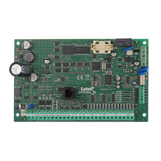
Page 13: Description Of The Mainboards
SATEL INTEGRA 5.4.1 Description of the mainboards Fig. 2. INTEGRA 24 control panel mainboard (version 1.5 E). Explanations for Fig. 2, 3 and 4: fuse for the battery charging circuit. battery connection cables (red +, black -). pins for setting battery charging current: ... - Page 14 Installer Manual SATEL lithium battery for clock and RAM backup. Its removal will result in loss of the clock settings and all data stored in RAM. Insert the battery in its socket just before starting the control panel (but not earlier).
- Page 15 SATEL INTEGRA...
-
Page 16: Connecting Devices To The Keypad Bus
Installer Manual SATEL Description of terminals: - power supply inputs - common ground - programmable outputs (n=output number): OUTn OUT1...OUT2 (INTEGRA 24 and INTEGRA 32) high-current: OUT1...OUT4 (INTEGRA 64 and INTEGRA 128) OUT3...OUT4 (INTEGRA24) low-current: OUT3...OUT8 (INTEGRA 32) OUT5...OUT16 (INTEGRA 64 and INTEGRA 128) -
Page 17: Addressing Devices Connected To The Keypad Bus
SATEL INTEGRA Fig. 5. Connection of keypads (other devices should be connected in a similar way). 5.5.1 Addressing devices connected to the keypad bus Each device to be connected to the keypad bus must have its own individual address from the 0 to 3 (INTEGRA 24 and INTEGRA 32) or from the 0 to 7 (INTEGRA 64 and INTEGRA 128) range. -
Page 18: Numeration Of Keypad Zones
Installer Manual SATEL n=0...7, currently set keypad address Fig. 6. Programming the keypad address with the service function. 6. To terminate the address change function, press the key. The function will be terminated automatically after 2 minutes from being started. Termination of the function is equivalent to restarting the keypad (the service mode menu will be displayed on the keypad with the lowest address). -
Page 19: Connecting Computer To The Keypad Rs-232 Port
SATEL INTEGRA 5.5.3 Connecting computer to the keypad RS-232 port In some keypads, the RS-232 port makes it possible to connect a computer with the GUARDX program installed (see Fig. 7). It is recommended that the straight-through unscreened cable be used for making the connection (using the twisted-pair type of cable, e.g. -
Page 20: Connecting The Int-Vg Or Int-Av Module Or Ca-64 Sm Expander
Installer Manual SATEL The bus wires must be run in one cable. The total length of the expander bus may not exceed 1000 m. The module may be powered directly from the control panel if the distance between control panel and module does not exceed 300 m. Where the distance is greater, another source of power must be provided for the module (a power supply unit or an expander with power supply). -
Page 21: Connecting The Detectors
SATEL INTEGRA If the device is connected to the second bus, its address in the system can be determined by adding the number 32 to the address set in it. The address affects numeration of zones and outputs in the system (see section p. -
Page 22: End-Of-Line Resistors
Installer Manual SATEL 5.7.1 End-of-line resistors For the control panel mainboard zones, use a 2.2 k resistor in Single EOL configuration and two 1.1 k resistors in Double EOL (2EOL) configuration. For some expanders, as well as for the INT-KSG keypad, the value of end-of-line resistors is programmable within the 500 ... -
Page 23: Connecting Power Supply
SATEL INTEGRA The system installer should inform the user about the way of connecting the control panel to the telephone network. The control panel must be connected directly to the telephone line (terminals marked TIP, RING). Other devices using the telephone line (e.g. telephone, fax) should be connected after the control panel (terminals marked T-1, R-1). -
Page 24: Backup Power Supply
Installer Manual SATEL The INTEGRA 64 and INTEGRA 128 control panels require 20 V AC (±10%) power supply. It is recommended that a transformer with at least 60 VA rating be used. Never connect two devices with power supply unit to one transformer. -
Page 25: First Start-Up Of The Control Panel
SATEL INTEGRA 5.11 First start-up of the control panel After the first start-up of the control panel, it is advisable to restore the factory S default settings using the C function ([S LEAR ALL ERVICE CODE ERVICE MODE R C ), and then quit the service mode. -
Page 26: Connecting Computer To The Control Panel
Installer Manual SATEL C 5. Restore the factory default settings using the C function (R LEAR ALL ESTARTS LEAR 6. Start the K . function (S H I K EYPADS ADDR TRUCTURE ARDWARE DENTIFICATION EYPADS .) and set individual addresses in the keypads (see p. 15). - Page 27 SATEL INTEGRA Fig. 14. Diagram of external analog modem connection to the control panel. 6 43 Fig. 15. Connection of the RS-232 ports of control panel and modem with the DB-9 socket. Shown on the left is RJ plug to be connected into the control panel mainboard socket. Shown on the right is DB-9 male plug (solder side view).
-
Page 28: Configuring Settings Of The Modem To Be Connected To Control Panel
(the SATEL made ETHM-1 / ETHM-1 Plus and GSM modules are connected in a similar way). Shown on the left is RJ plug to be connected into the control panel mainboard socket. Shown on the right is PIN5 plug. A ready cable is offered by SATEL company (RJ/PIN5). -
Page 29: Connecting The Printer
SATEL INTEGRA Fig. 18. Proper setting of the external modem parameters. 5.15 Connecting the printer The control panel RS-232 port makes it possible to connect a printer provided with serial port. The control panel may print events in a “compressed” format (single event is printed in a single line containing up to 80 characters) or “extended”... -
Page 30: Numeration Of Zones And Outputs In The System
Installer Manual SATEL Fig. 20. Connection of printer by means of DIN 5-pin plug (solder side view). Shown on the left is RJ plug to be connected into the control panel mainboard socket. 6. Numeration of zones and outputs in the system Numbers are automatically assigned to the zones and outputs: ... -
Page 31: Specifications
SATEL INTEGRA 7. Specifications Control panel INTEGRA 24 INTEGRA 32 INTEGRA 64 INTEGRA 128 Supply voltage 18 V AC ±15%, 50-60 Hz 20 V AC ±15%, 50-60 Hz Recommended transformer 40 VA 60 VA Standby current consumption 121 mA 127 mA... -
Page 32: Int-Klcd Keypad
Installer Manual SATEL 7.2 INT-KLCD keypad Supply voltage ....................12 V DC ±15% Standby current consumption ..................17 mA Maximum current consumption ..................101 mA Environmental class according to EN50130-5 .................II Operating temperature range................. -10…+55 °C Maximum humidity ......................93±3% Enclosure dimensions ................. 140 x 126 x 26 mm Weight.......................... -
Page 33: Int-Klfr Keypad
SATEL INTEGRA Maximum current consumption..................110 mA Environmental class according to EN50130-5 ................. II Operating temperature range................. -10…+55 °C Maximum humidity ......................93±3% Enclosure dimensions..................160 x 132 x 29 mm Weight..........................317 g INT-KLFR keypad Supply voltage ....................12 V DC ±15% Standby current consumption ..................60 mA...
Need help?
Do you have a question about the INTEGRA Series and is the answer not in the manual?
Questions and answers