Panasonic HL-G1 Series User Manual
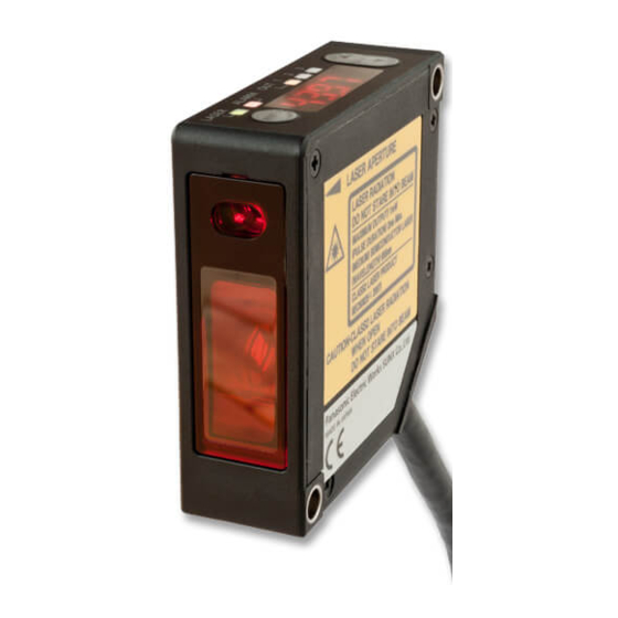
Compact laser displacement sensor
Hide thumbs
Also See for HL-G1 Series:
- User manual (158 pages) ,
- Manual (16 pages) ,
- Instruction manual (4 pages)
Table of Contents
Advertisement
Quick Links
Download this manual
See also:
User Manual
Advertisement
Table of Contents

Related Manuals for Panasonic HL-G1 Series


Summary of Contents for Panasonic HL-G1 Series
- Page 1 USER'S MANUAL Compact Laser Displacement Sensor HL-G1 Series (Console-dedicated Version) ME-HLG1DP(05)
-
Page 2: Introduction
4. The utmost attention has been paid to the creation of this manual. Should you find any errors, omissions or inaccuracies, contact the nearest office of Panasonic Industrial Devices SUNX Co., Ltd. 5. Panasonic Industrial Devices SUNX Co., Ltd. shall be in no case responsible for any consequences resulting from your operation of the product. Conventions The following conventions are used to indicate and classify precautions in this manual. -
Page 3: Table Of Contents
Introduction ......................0 Table of Contents ....................... 1 1. Introduction of HL-G1 Dedicated Console ............2 1-1 Using GT Series for HL-G1 Series................2 1-2 Applicable Programmable Display Models..............3 1-3 Steps to Introduce Dedicated Console................4 2. Nomenclature ..................... 5 3. -
Page 4: Introduction Of Hl-G1 Dedicated Console
1-1 Using GT Series for HL-G1 Series The HL-G1□□-S-J Compact Laser Displacement Sensor (a high-functional model of the HL-G1 Series) will work as a dedicated console or USB/RS-485 converter if the Panasonic Industrial Devices SUNX's GT-series Programmable Display is connected to the HL-G1□□-S-J and dedicated screen data is written to the Programmable Display. -
Page 5: Applicable Programmable Display Models
HL-G1 Series User’s Manual (Console-dedicated Version) 1-2 Applicable Programmable Display Models Panasonic Industrial Devices SUNX's GT-series Programmable Display (any of the following models sold separately) can be used as a dedicated console by connecting the Programmable Display to the high-functional model (HL-G1□□-S-J) of the HL-G1 Compact Laser Displacement Sensor and writing dedicated screen data to the Programmable Display. -
Page 6: Steps To Introduce Dedicated Console
HL-G1 Series User’s Manual (Console-dedicated Version) 1-3 Steps to Introduce Dedicated Console This section provides brief information on the introduction of the GT Series as a dedicated console. For the procedure in detail, refer to "3. Acquiring and Writing Screen Data”. -
Page 7: Nomenclature
1 2 3 4 MODE Reserved (not used) Always turned OFF The SD memory card slot or internal battery is not used in the case of using either one of the above as a dedicated console for the HL-G1 Series. -
Page 8: Acquiring And Writing Screen Data
B-E-20120101 Software License Agreement Panasonic Industrial Devices SUNX Co., Ltd. (“PIDSX”) grants to you a license to use this Software on condition that you accept this Agreement. You must read this Software License Agreement (this “Agreement”) carefully before using this Software. - Page 9 HL-G1 Series User’s Manual (Console-dedicated Version) LIMITED TO THE IMPLIED WARRANTIES OF MARCHANTABILITY, FITNESS FOR PARTICULAR PURPOSE, AND NON-INFRINGEMENT OF THIRD PARTY RIGHTS. 3-2. UNDER NO CIRCUMSTANCES SHALL PIDSX BE LIABLE FOR ANY DAMAGES (INCLUDING DIRECT, INDIRECT, INCIDENTAL, CONSEQUENTIAL OR SPECIAL OR WHATSOEVER) ARISING OUT OF THE USE OF THIS SOFTWARE, INABILITY TO USE THIS SOFTWARE, DEFECTS IN THIS SOFTWARE (e.g., BUGS, SECURITY...
- Page 10 HL-G1 Series User’s Manual (Console-dedicated Version) otherwise at the time of provision of such upgrades or updates. Article 8 Limitation on Liability AGGREGATE LIABILITIES OF PIDSX IN CONNECTION WITH THIS AGREEMENT OR THIS SOFTWARE SHALL IN NO EVENT EXCEED TEN THOUSAND (10,000) YEN.
-
Page 11: Downloading Dedicated Software
AIG12MQ14D GT12M AIG12MQ05D AIG12MQ15D Go to the download page from the top page of Panasonic Industrial Devices SUNX's website. http://panasonic.net/id/pidsx/global Download the applicable data file from the page for "HL-G1-series Compact Laser Displacement Sensor". The downloading file is compressed (in zip). Uncompress the file in an... -
Page 12: Installation Of Gt Virtual Uart Driver
HL-G1 Series User’s Manual (Console-dedicated Version) 3-3 Installation of GT Virtual UART Driver The GT Virtual UART driver is required when writing screen data from the PC. Therefore, the GT Virtual UART driver must be installed to the PC before writing screen data. - Page 13 HL-G1 Series User’s Manual (Console-dedicated Version) Select "System and Security" in the Control Panel. Select "System" in the System and Securityl. Select "Device Manager" in the System. The User Account Control window will be displayed. Click "Continue (C)."...
- Page 14 HL-G1 Series User’s Manual (Console-dedicated Version) Right-click "Panasonic GT" in the Device Manager window, and select "Update Driver." The Update Driver window will be displayed. Click "Browse my computer for driver software (R)." A list of drivers will appear. Select the folder copied and expanded in...
- Page 15 HL-G1 Series User’s Manual (Console-dedicated Version) The Windows Security window will be displayed. Click "Install this driver (I). The Update Complete window will be displayed. Click "Close (C)." The installation of the GT Virtual UART driver to the PC will be completed at...
-
Page 16: Writing Screen Data
HL-G1 Series User’s Manual (Console-dedicated Version) 3-4 Writing Screen Data Click the "GTDownLoader.exe" in the folder where the file has been expanded. The message "Execute Download?" will be displayed in the prompt screen for the screen data. Select the COM port where GT is connected, and click the "OK"... -
Page 17: Sensor Connections And Initial Settings
HL-G1 Series User’s Manual (Console-dedicated Version) 4. Sensor Connections and Initial Settings 4-1 Mounting Console For the installation of the GT Series in detail, refer to "Chapter 3 Installation and Wiring" of the "GT-series User's Manual”. Use the four mounting brackets and four mounting screws provided and mount the console to the mounting plate. -
Page 18: Connecting Dedicated Console To Hl-G1
HL-G1 Series User’s Manual (Console-dedicated Version) 4-2 Connecting Dedicated Console to HL-G1 For general handling information on the GT Series, refer to the GT-series User’s Manual. ● Connecting GT12 Series to HL-G1 (More than a single HL-G1 unit over RS-485) •... -
Page 19: Hl-G1 Settings
HL-G1 Series User’s Manual (Console-dedicated Version) 4-3 HL-G1 Settings Before using the compact console (GT-series unit) for communication with the HL-G1, select and set communications conditions on the HL-G1 side according to the communications specifications. ● HL-G1 Settings for communications conditions... -
Page 20: Changing And Saving Display Language Of Console
HL-G1 Series User’s Manual (Console-dedicated Version) 4-4 Changing and Saving Display Language of Console The console screen will display in English when the console is started with the sensor head connected after screen data is written. Environment settings for the console are required to change the displayed language on the screen. -
Page 21: Screen Configuration And Basic Operation
HL-G1 Series User’s Manual (Console-dedicated Version) 5. Screen Configuration and Basic Operation 5-1 Top Menu Screen and Basic Buttons ● Top menu GT12 top menu GT02 top menu The top menu screen shows the above items. The user can move to other screens through here. -
Page 22: Basic Console Operation
HL-G1 Series User’s Manual (Console-dedicated Version) 5-2 Basic Console Operation Moving between Setting Screens The operation screen is of hierarchic structure. Touch the Up and Down Keys ( ) to go to the target screen and make necessary settings. ····· The value of each item in the sensor setting menus (Pro1 through Pro7) will increase by 1. - Page 23 HL-G1 Series User’s Manual (Console-dedicated Version) Selection This section provides information on how to select the target item from multiple choices. [Selection from a few choices] The selectable item changes as shown each time the key is touched. Emission Emission...
- Page 24 HL-G1 Series User’s Manual (Console-dedicated Version) Numeric Input Set value This section provides information on how to input numeric values, such as limit values and offset values. The keyboard will be displayed Decimal point Enter for items for which numeric input is possible.
-
Page 25: Console-Dedicated Functions
HL-G1 Series User’s Manual (Console-dedicated Version) 5-3 Console-dedicated Functions Output setting menu (GT-12 setting screen) ● Display console measurement value Use this function to fix the console measurement value after the decimal point to 0. Set this item to disable the change in the display of the minute measurement value of the console. - Page 26 HL-G1 Series User’s Manual (Console-dedicated Version) ● Panel lock Use this function to prevent set value changes with console key manipulation. It is possible to move between screens. Set value: ON, OFF ● Touch beep Use this function to enable or disable the touch beep.
-
Page 27: Screen Transition Charts
HL-G1 Series User’s Manual (Console-dedicated Version) 6. Screen Transition Charts This section provides screen transition charts of the console dedicated to HL-G1. For details of each function, refer to the HL-G1 User's Manual provided with the sensor head. 6-1 GT02 Screen Transition ●... - Page 28 HL-G1 Series User’s Manual (Console-dedicated Version) ● Setting item screen for each setting menu (for GT02 use) Pro1: Sensing setting menu Pro2: Data processing menu Pro3: Output setting menu Sampling cycle Average times Judgment output selection Displacement judgment (Threshold a)
- Page 29 HL-G1 Series User’s Manual (Console-dedicated Version) Pro4: Analog setting menu Pro5: Alarm setting menu Pro7: System setting menu Analog output selection Analog output at alarm Timing mode Analog scaling (current) Digital output at alarm Laser control Analog scaling (voltage) Alarm delay times...
-
Page 30: Gt12 Screen Transition
HL-G1 Series User’s Manual (Console-dedicated Version) 6-2 GT12 Screen Transition ● Transition from top screen to each menu screen Top screen Environment setting menu Sensor setting menu Measurement value display [ALL] Sensor setting menu [NO. 1] Memory change Pro1 Sensing setting... - Page 31 HL-G1 Series User’s Manual (Console-dedicated Version) ● Setting item screen for each setting menu (for GT12 use) Pro1: Sensing setting menu Pro2: Data processing menu Pro3: Output setting menu Sampling cycle Average times Judgment output selection Shutter time Analysis mode...
- Page 32 HL-G1 Series User’s Manual (Console-dedicated Version) Pro7: System setting menu Pro4: Analog setting menu Pro5: Alarm setting menu Analog output selection Analog output at alarm Timing mode Analog scaling (current) Digital output at alarm Laser control Analog scaling (voltage) Alarm delay times...
-
Page 33: Procedure For Deleting Gt_Usb Driver
HL-G1 Series User’s Manual (Console-dedicated Version) 7. Procedure for Deleting GT_USB Driver The conventional GT_USB driver, if already installed, must be deleted before installing the GT Virtual UART driver. Pay the utmost attention not to delete other drivers. Devices will not operate if the corresponding drivers are deleted. - Page 34 HL-G1 Series User’s Manual (Console-dedicated Version) Select "System and Security" in the Control Panel. Double-click "System and Security." Select "System" in the System and Security. Double-click "System." Select "Device Manager" in the System. Click "Device Manager." The User Account Control window will be displayed. Click "Continue (C)."...
- Page 35 HL-G1 Series User’s Manual (Console-dedicated Version) Right-click "Panasonic GT USB Driver Ver1.0" in the Device Manager window, and select "Uninstall" Make sure not to delete drivers other than Panasonic GT USB Driver Ver1.0 for the GT. Click "USB (Universal Serial Bus) Drivers" in the Device Tree.
- Page 36 HL-G1 Series User’s Manual (Console-dedicated Version) Revision history Released date Revision No. October 2010 A first release December 2010 The 1st edition January 2011 The 2nd edition February 2013 The 3 edition September 2013 The 4 edition...
- Page 37 Overseas Sales Division (Head Office) 2431-1 Ushiyama-cho, Kasugai-shi, Aichi, 486-0901, Japan Phone: +81-568-33-7861 FAX: +81-568-33-8591 About our sale network, please visit our website. PRINTED IN JAPAN © Panasonic Industrial Devices SUNX Co., Ltd. 2013 September 2013...