Panasonic HL-G1 Series Manuals
Manuals and User Guides for Panasonic HL-G1 Series. We have 6 Panasonic HL-G1 Series manuals available for free PDF download: User Manual, Manual, Instruction Manual

Panasonic HL-G1 Series User Manual (158 pages)
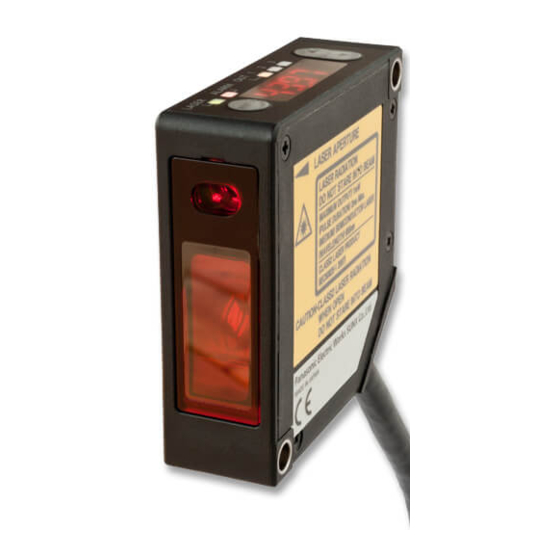
Compact Laser Displacement Sensor
Brand: Panasonic
|
Category: Security Sensors
|
Size: 2.02 MB
Table of Contents
Advertisement

Panasonic HL-G1 Series User Manual (152 pages)
Compact Laser Displacement Sensor
Brand: Panasonic
|
Category: Accessories
|
Size: 2.02 MB
Table of Contents

Panasonic HL-G1 Series User Manual (145 pages)
laser displacement sensor
Brand: Panasonic
|
Category: Accessories
|
Size: 9.24 MB
Table of Contents
Advertisement

Panasonic HL-G1 Series User Manual (37 pages)
Compact Laser Displacement Sensor
Brand: Panasonic
|
Category: Accessories
|
Size: 1.4 MB
Table of Contents
Panasonic HL-G1 Series Manual (16 pages)
Compact Laser Displacement Sensor
Brand: Panasonic
|
Category: Accessories
|
Size: 3.01 MB
Table of Contents

Panasonic HL-G1 Series Instruction Manual (4 pages)
Compact Laser Displacement Sensor
Brand: Panasonic
|
Category: Accessories
|
Size: 1.08 MB