
Related Manuals for JLG H340AJ


Summary of Contents for JLG H340AJ
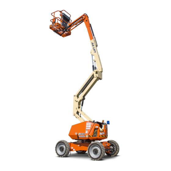
- Page 1 Operation and Safety Manual Original Instructions - Keep this manual with the machine at all times. Boom Lift Models H340AJ ANSI AS/NZS 3121633 ® November 5, 2018 - Rev G...
- Page 2 WARNING Operating, servicing and maintaining this vehicle or equipment can expose you to chemicals including engine exhaust, carbon monoxide, phthalates, and lead, which are known to the State of California to cause cancer and birth defects or other reproductive harm. To minimize exposure, avoid breathing exhaust, do not idle the engine except as necessary, service your vehicle or equipment in a well-ventilated area and wear gloves or wash your hands frequently when servicing.
- Page 3 The purpose of this manual is to provide owners, users, operators, lessors, and lessees with the precautions and operating procedures essential for the safe and proper machine operation for its intended purpose. Due to continuous product improvements, JLG Industries, Inc. reserves the right to make specification changes without prior notification. Contact JLG Industries, Inc. for updated information.
- Page 4 FOREWORD SAFETY ALERT SYMBOLS AND SAFETY SIGNAL WORDS This is the Safety Alert Symbol. It is used to alert you to the potential personal injury hazards. Obey all safety messages that follow this symbol to avoid possible injury or death INDICATES A POTENTIALLY HAZARDOUS SITUATION.
- Page 5 Modifications Product Safety JLG INDUSTRIES, INC. SENDS SAFETY RELATED BULLETINS TO THE OWNER OF RECORD OF THIS MACHINE. CONTACT JLG INDUSTRIES, INC. TO ENSURE THAT THE Contact: CURRENT OWNER RECORDS ARE UPDATED AND ACCURATE. Product Safety and Reliability Department JLG Industries, Inc.
- Page 6 FOREWORD REVISION LOG Original Issue A - January 13, 2015 Revised B - April 25, 2017 Revised C - June 5, 2017 Revised D - September 25, 2017 Revised E - February 28, 2018 Revised F - June 29, 2018 - Revised Covers, Prop 65 Revised G - November 5, 2018 3121633...
-
Page 7: Table Of Contents
TABLE OF CONTENTS SECTION - PARAGRAPH, SUBJECT PAGE SECTION - PARAGRAPH, SUBJECT PAGE SECTION - 1 - SAFETY PRECAUTIONS Function Check........2-8 SkyGuard Function Test. - Page 8 TABLE OF CONTENTS SECTION - PARAGRAPH, SUBJECT PAGE SECTION - PARAGRAPH, SUBJECT PAGE TRAVELING (DRIVING) ....... . 4-8 4.13 SHUT DOWN AND PARK/STORAGE POSITION .
- Page 9 TABLE OF CONTENTS SECTION - PARAGRAPH, SUBJECT PAGE SECTION - PARAGRAPH, SUBJECT PAGE Dimensional Data ....... . . 6-2 Capacities .
- Page 10 TABLE OF CONTENTS SECTION - PARAGRAPH, SUBJECT PAGE SECTION - PARAGRAPH, SUBJECT PAGE This Page Left Blank Intentionally 3121633...
- Page 11 LIST OF FIGURES FIGURE NUMBER - TITLE PAGE FIGURE NUMBER - TITLE PAGE 2-1. Basic Nomenclature........2-4 4-19.
- Page 12 LIST OF FIGURES FIGURE NUMBER - TITLE PAGE FIGURE NUMBER - TITLE PAGE This Page Left Blank Intentionally 3121633...
- Page 13 LIST OF TABLES TABLE NUMBER - TITLE PAGE TABLE NUMBER - TITLE PAGE Minimum Approach Distances (M.A.D.) ....1-6 Beaufort Scale (For Reference Only)....1-9 Inspection and Maintenance Table .
- Page 14 LIST OF TABLES TABLE NUMBER - TITLE PAGE TABLE NUMBER - TITLE PAGE This Page Left Blank Intentionally viii 3121633...
-
Page 15: Section 1 - Safety Precautions
JLG Industries, Inc. completed under the supervision of an experienced and quali- fied operator. -
Page 16: Workplace Inspection
JLG. unit. • Before operation, check work area for overhead hazards such •... -
Page 17: Machine Inspection
• Check the machine for modifications to original components. opposite direction. Always return switch to neutral and stop Ensure that any modifications have been approved by JLG. before moving the switch to the next function. Operate con- trols with slow and even pressure. -
Page 18: Trip And Fall Hazards
• Do not carry materials directly on platform railing unless • Hydraulic cylinders are subject to thermal expansion and con- approved by JLG. traction. This may result in changes to the boom and/or plat- form position while the machine is stationary. Factors •... -
Page 19: Electrocution Hazards
SECTION 1 - SAFETY PRECAUTIONS • Before operating the machine, make sure all gates are closed Electrocution Hazards and fastened in their proper position. • This machine is not insulated and does not provide protection from contact or proximity to electrical current. •... - Page 20 SECTION 1 - SAFETY PRECAUTIONS Table 1-1. Minimum Approach Distances (M.A.D.) Voltage Range MINIMUM APPROACH DISTANCE (Phase to Phase) in Feet (Meters) 0 to 50 KV 10 (3) Over 50KV to 200 KV 15 (5) Over 200 KV to 350 KV 20 (6) Over 350 KV to 500 KV 25 (8)
-
Page 21: Tipping Hazards
SECTION 1 - SAFETY PRECAUTIONS • The minimum approach distance may be reduced if insulating Tipping Hazards barriers are installed to prevent contact, and the barriers are • The user must be familiar with the surface before driving. Do rated for the voltage of the line being guarded. These barriers not exceed the allowable sideslope and grade while driving. - Page 22 Keep all loads within the confines of the platform, gusts, may exceed 28 mph (12.5 m/s). Factors affecting wind unless authorized by JLG. speed are; platform elevation, surrounding structures, local weather events, and approaching storms. Refer to Table 1-2, •...
- Page 23 SECTION 1 - SAFETY PRECAUTIONS DO NOT OPERATE THE MACHINE WHEN WIND CONDITIONS EXCEED 28 MPH (12.5 M/ Table 1-2. Beaufort Scale (For Reference Only) Wind Speed Beaufort Description Land Conditions Number 0-0.2 Calm Calm. Smoke rises vertically 0.3-1.5 Light air Wind motion visible in smoke 1.6-3.3 Light breeze...
-
Page 24: Crushing And Collision Hazards
SECTION 1 - SAFETY PRECAUTIONS Crushing and Collision Hazards • Keep non-operating personnel at least 6 ft. (1.8m) away from machine during all driving and swing operations. • Approved head gear must be worn by all operating and • Under all travel conditions, the operator must limit travel ground personnel. -
Page 25: Towing, Lifting, And Hauling
SECTION 1 - SAFETY PRECAUTIONS TOWING, LIFTING, AND HAULING MAINTENANCE • Never allow personnel in platform while towing, lifting, or This sub-section contains general safety precautions which must hauling. be observed during maintenance of this machine. Additional pre- cautions to be observed during machine maintenance are •... - Page 26 SECTION 1 - SAFETY PRECAUTIONS • DO NOT use your hand to check for leaks. Use a piece of card- • Do not use machine as a ground for welding. board or paper to search for leaks. Wear gloves to help protect •...
-
Page 27: Battery Hazards
SECTION 1 - SAFETY PRECAUTIONS Battery Hazards • Always disconnect batteries when servicing electrical compo- BATTERY FLUID IS HIGHLY CORROSIVE. AVOID CONTACT WITH SKIN AND CLOTHING AT ALL TIMES. IMMEDIATELY RINSE ANY CONTACTED AREA WITH CLEAN WATER AND nents or when performing welding on the machine. SEEK MEDICAL ATTENTION. - Page 28 SECTION 1 - SAFETY PRECAUTIONS NOTES: 1-14 3121633...
-
Page 29: Section 2. User Responsibilities, Machine Preparation, And Inspection
SECTION 2 - USER RESPONSIBILITIES, MACHINE PREPARATION, AND INSPECTION SECTION 2. USER RESPONSIBILITIES, MACHINE PREPARATION, AND INSPECTION 2.1 PERSONNEL TRAINING 6. The safest means to operate the machine where overhead obstructions, other moving equipment, and obstacles, The aerial platform is a personnel handling device; so it is neces- depressions, holes, or drop-offs exist. -
Page 30: 2.2 Preparation, Inspection, And Maintenance
SECTION 2 - USER RESPONSIBILITIES, MACHINE PREPARATION, AND INSPECTION 2.2 PREPARATION, INSPECTION, AND MAINTENANCE JLG INDUSTRIES, INC. RECOGNIZES A FACTORY TRAINED SERVICE TECHNICIAN AS A The following table covers the periodic machine inspections and PERSON WHO HAS SUCCESSFULLY COMPLETED THE JLG SERVICE TRAINING SCHOOL maintenance required by JLG Industries, Inc. - Page 31 Preventative Maintenance At intervals as specified in the Service and Maintenance Owner, Dealer, or User Qualified JLG Mechanic Service and Maintenance Manual Manual. NOTE: Inspection forms are available from JLG. Use the Service and Maintenance Manual to perform inspections. 3121633...
- Page 32 SECTION 2 - USER RESPONSIBILITIES, MACHINE PREPARATION, AND INSPECTION 1. Platform 2. Platform Console 3. SkyGuard (If Equipped) 4. Cross Rail 5. Jib 6. Fly Boom Section 7. Base Boom Section 8. Main Lift Cylinder 9. Master Cylinder 10. Upper Upright 11.
-
Page 33: Pre-Start Inspection
SECTION 2 - USER RESPONSIBILITIES, MACHINE PREPARATION, AND INSPECTION Pre-Start Inspection 5. Daily Walk-Around Inspection – Perform as instructed. 6. Battery – Charge as required. The Pre-Start Inspection should include each of the following: 7. Fuel (Combustion Engine Powered Machines) – Add the 1. -
Page 34: Daily Walk-Around Inspection
SECTION 2 - USER RESPONSIBILITIES, MACHINE PREPARATION, AND INSPECTION Daily Walk-Around Inspection OAC00300 3121633... - Page 35 SECTION 2 - USER RESPONSIBILITIES, MACHINE PREPARATION, AND INSPECTION General 5. Wheel/Tire Assemblies - Properly secured, no missing lug nuts. Inspect for worn tread, cuts, tears or other discrepan- cies. Inspect wheels for damage and corrosion. Begin the "Walk-Around Inspection" at Item 1, as noted on the diagram.
-
Page 36: Function Check
SECTION 2 - USER RESPONSIBILITIES, MACHINE PREPARATION, AND INSPECTION Function Check 4. Watch the Indicator Gauge on the Ground Control Console to verify the power is discon- Prior to performing the function check, verify that the battery dis- nected. connect on the side of the frame works properly. 1. - Page 37 SECTION 2 - USER RESPONSIBILITIES, MACHINE PREPARATION, AND INSPECTION Perform the Function Check as follows: 3. With the platform in the stowed position: 1. From the ground control console with no load in the plat- a. Drive the machine on a grade, not to exceed the rated form: gradeability, and stop to ensure the brakes hold;...
-
Page 38: Skyguard Function Test
SECTION 2 - USER RESPONSIBILITIES, MACHINE PREPARATION, AND INSPECTION SkyGuard Function Test 4. Disengage the SkyGuard sensor, release controls, then recy- cle the footswitch. Ensure normal operation is available. NOTE: Refer to Section 4.12 for additional information on SkyGuard NOTE: On machines equipped with SkyLine, reattach magnetic end of operation. -
Page 39: Oscillating Axle Lockout Test (If Equipped)
SECTION 2 - USER RESPONSIBILITIES, MACHINE PREPARATION, AND INSPECTION OSCILLATING AXLE LOCKOUT TEST (IF EQUIPPED) boom reaches center, stowed position, lockout cylinders should release and allow wheel to rest on ground, it may be necessary to activate Drive to release cylinders. 8. - Page 40 SECTION 2 - USER RESPONSIBILITIES, MACHINE PREPARATION, AND INSPECTION NOTES: 2-12 3121633...
-
Page 41: Section 3 - Machine Controls And Indicators
SECTION 3 - MACHINE CONTROLS AND INDICATORS SECTION 3. MACHINE CONTROLS AND INDICATORS GENERAL NOTE: The indicator panels use different shaped symbols to alert the operator to different types of operational situations that could arise. The meaning of those symbols are explained below. Indicates a potentially hazardous situation, which if THE MANUFACTURER HAS NO DIRECT CONTROL OVER MACHINE APPLICATION AND not corrected, could result in serious injury or death. -
Page 42: Ground Control Console
SECTION 3 - MACHINE CONTROLS AND INDICATORS 2. Indicator Gauge Registers the amount of time the machine TO AVOID SERIOUS INJURY, DO NOT OPERATE MACHINE IF ANY CONTROL LEVERS OR has been in use, with functions operating and TOGGLE SWITCHES CONTROLLING PLATFORM MOVEMENT DO NOT RETURN TO THE also displays the state of battery discharge. - Page 43 SECTION 3 - MACHINE CONTROLS AND INDICATORS 1. Indicator Panel 2. Indicator Gauge 3. Power/Emergency Stop 4. Platform/Ground Select 5. Telescope 6. Not Used 7. Main Boom Lift 8. Tower Boom Lift 9. Swing 10. Engine Start/Auxiliary Descent Enable/ Function Enable 11.
- Page 44 SECTION 3 - MACHINE CONTROLS AND INDICATORS 1. Indicator Panel 2. Indicator Gauge 3. Power/Emergency Stop 4. Platform/Ground Select 5. Telescope 6. Machine Safety System Override (MSSO) 7. Main Boom Lift 8. Tower Boom Lift 9. Swing 10. Engine Start/Auxiliary Descent Enable/ Function Enable 11.
- Page 45 SECTION 3 - MACHINE CONTROLS AND INDICATORS NOTE: When the Platform/Ground Select Switch is in the center posi- 6. Machine Safety System Override (MSSO) (CE tion, power is shut off to the controls at both operating consoles. Only) Remove the key to prevent the controls from being actuated. Provides emergency override of function 4.
- Page 46 SECTION 3 - MACHINE CONTROLS AND INDICATORS 9. Swing Provides 355 degrees non-con- ONLY USE THE PLATFORM LEVELING OVERRIDE FUNCTION FOR SLIGHT LEVELING OF tinuous turntable rotation. THE PLATFORM. INCORRECT USE COULD CAUSE THE LOAD/OCCUPANTS TO SHIFT OR FALL. FAILURE TO DO SO COULD RESULT IN DEATH OR SERIOUS INJURY. 12.
-
Page 47: Ground Control Indicator Panel
Indicates the Drive and Steer Disable function has been activated. 7. System Distress Indicator 2. High Engine Temperature Indicator The light indicates that the JLG Control System Indicates that engine coolant temperature is has detected an abnormal condition and a abnormally high and service is required. - Page 48 SECTION 3 - MACHINE CONTROLS AND INDICATORS 1. Drive and Steer Disable 2. High Engine Coolant Temperature 3. Low Engine Oil Pressure 4. Genset Automatic 5. Low Fuel 6. Glow Plug 7. System Distress 8. Platform Overload Figure 3-3. Ground Control Indicator Panel 3121633...
-
Page 49: Platform Console
SECTION 3 - MACHINE CONTROLS AND INDICATORS Platform Console ONLY USE THE PLATFORM LEVELING OVERRIDE FUNCTION FOR SLIGHT LEVELING OF (See Figure 3-4., Platform Control Console) THE PLATFORM. INCORRECT USE COULD CAUSE THE LOAD/OCCUPANTS TO SHIFT OR FALL. FAILURE TO DO SO COULD RESULT IN DEATH OR SERIOUS INJURY. 2. - Page 50 SECTION 3 - MACHINE CONTROLS AND INDICATORS 1. Maximum Speed/Reduced Speed 7. Drive Orientation Override 13. Tower Boom Lift 2. Platform Leveling Override 8. Drive/Steer 14. SkyGuard Indicator 3. Horn 9. Telescope 15. Platform Rotate 4. Power/Emergency Stop 10. Lights 16.
- Page 51 When in the on position NOTE: After turning on ignition, the JLG Control System (and the ground Emergency Stop Switch on will wait until glow plug indicator light goes out [pulled out]), the generator is enabled to automatically start before cranking engine.
- Page 52 SECTION 3 - MACHINE CONTROLS AND INDICATORS NOTE: To operate the Drive joystick, pull up on the lock- 11. Jib Lift ing ring below the handle. Provides for raising or lowering of the jib by positioning up/down. NOTE: The Drive joystick is spring loaded and will auto- 12.
- Page 53 SECTION 3 - MACHINE CONTROLS AND INDICATORS 15. Platform Rotate NOTE: To operate the Main Boom Lift/Swing joystick, pull up on the locking ring below the handle. Provides rotation of the platform when posi- tioned to the right or left. NOTE: The Main Boom Lift/Swing joystick is spring loaded and will automatically return to neutral...
-
Page 54: Platform Control Indicator Panel
SECTION 3 - MACHINE CONTROLS AND INDICATORS Platform Control Indicator Panel 3. Tilt Alarm Warning Light and Alarm This red illuminator indicates that the chassis is (See Figure 3-5., Platform Control Indicator Panel) on a slope. An alarm will also sound when the chassis is on an excessive slope and the boom NOTE: The indicator lights will illuminate for approximately 1 second... - Page 55 SECTION 3 - MACHINE CONTROLS AND INDICATORS 1001170083 C 1. AC Inverter 5. Enable/Footswitch 8. System Distress 2. Platform Overload 6. Fuel Level 9. Drive Orientation 3. Tilt 7. Creep 10. Low Battery 4. Glow Plug/Wait to Start Figure 3-5. Platform Control Indicator Panel 3121633 3-15...
- Page 56 SECTION 3 - MACHINE CONTROLS AND INDICATORS 4. Glow Plug/Wait to Start Indicator 6. Fuel Level Indicator Indicates the glow plugs are operating. Indicates the level of fuel in the tank. 5. Enable Indicator/Footswitch To operate any function, the footswitch must be depressed and the function selected within seven seconds.
- Page 57 (i.e. controls reversed situations). 8. System Distress Indicator 10. Low Battery Indicator The light indicates that the JLG Control System Indicates the batteries are low and need to be has detected an abnormal condition and a charged.
- Page 58 SECTION 3 - MACHINE CONTROLS AND INDICATORS NOTES: 3-18 3121633...
-
Page 59: Section 4 - Machine Operation
SECTION 4 - MACHINE OPERATION SECTION 4. MACHINE OPERATION DESCRIPTION The primary operator control console is in the platform. From this control console, the operator can drive and steer the machine in This machine is a mobile elevating work platform used to posi- both forward and reverse directions. -
Page 60: Boom Operating Characteristics And Limitations
1. Machine is positioned on a smooth, firm and level surface. NOTE: Contact JLG Customer Service for operation under abnormal 2. Load is within manufacturers rated design capacity. conditions. 3. All machine systems are functioning properly. -
Page 61: Auto Start Mode
Ground. The JLG Control System will automatically start the engine when the Generator Enable switch is in the On position and the JLG Control system reads the battery stack state of charge is in a Low 2. Pull the Power/Emergency Stop switch to On. -
Page 62: Shutdown Procedure
SECTION 4 - MACHINE OPERATION 5. Turn Platform/Ground Select switch to Plat- Shutdown Procedure form. If the genset is in automatic mode, the engine will shut down 6. Pull out the Ground Console Power/Emer- IF AN ENGINE MALFUNCTION CAUSES AN UNSCHEDULED SHUTDOWN, DETERMINE gency Stop switch to provide power to the THE CAUSE AND CORRECT IT BEFORE RESTARTING THE ENGINE. -
Page 63: Jump Starting
Fuel Reserve / Shut-Off System (Diesel Engines Only) stack voltage that is too low in power for the GenSet module to start the engine. The JLG Control System senses the machine is in Jump Start mode when an external battery has been connected The Fuel Shutoff System senses when the fuel level is getting low to machine jump terminal. - Page 64 SECTION 4 - MACHINE OPERATION MAIN BOOM MAIN BOOM FULLY EXTENDED HORIZONTAL MACHINE WILL "TIP OVER" IN THIkyg DIRECTION IF OVERLOADED OR OPERATED ON AN LOWER BOOM FULLY ELEVATED OUT-OF-LEVEL SURFACE Figure 4-1. Position of Least Forward Stability 3121633...
- Page 65 SECTION 4 - MACHINE OPERATION PLATFORM ROTATED 90 DEGREES MACHINE WILL "TIP OVER" IN THIS DIRECTION IF OVERLOADED OR OPERATED ON AN OUT-OF-LEVEL SURFACE MAIN BOOM FULLY ELEVATED AND FULLY RETRACTED LOWER BOOM FULLY ELEVATED Figure 4-2. Position of Least Backward Stability 3121633...
-
Page 66: Traveling (Driving)
SECTION 4 - MACHINE OPERATION TRAVELING (DRIVING) DO NOT DRIVE WITH BOOM OUT OF TRANSPORT MODE EXCEPT ON A SMOOTH, FIRM See Figure 4-3., Grade and Side Slopes AND LEVEL SURFACE. NOTE: Refer to the Operating Specifications table for Gradeability and Sideslope ratings. - Page 67 SECTION 4 - MACHINE OPERATION G R A D E S ID E S L O P E LE V E L Figure 4-3. Grade and Side Slopes 3121633...
-
Page 68: Traveling Forward And Reverse
SECTION 4 - MACHINE OPERATION Traveling Forward and Reverse 2. Push and release the Drive Orientation Over- ride switch. Within 3 seconds, slowly move the Drive control toward the arrow matching the 1. At Platform Controls, pull out Emergency Stop intended direction of machine travel. -
Page 69: Traveling On A Grade
SECTION 4 - MACHINE OPERATION Traveling on a Grade STEERING Position thumb switch on Drive/Steer controller to When traveling a grade, maximum braking and traction are obtained Right for steering right, or to Left for steering left. with the boom stowed, in position over the rear (drive) axle, and in line with the direction of travel. -
Page 70: Platform
SECTION 4 - MACHINE OPERATION PLATFORM BOOM Platform Level Adjustment A RED TILT WARNING LIGHT IS LOCATED ON THE CONTROL CONSOLE WHICH LIGHTS WHEN THE CHASSIS IS ON AN EXCESSIVE SLOPE. DO NOT SWING OR RAISE BOOM ABOVE HORIZONTAL WHEN LIGHT IS ONLY USE THE PLATFORM LEVELING OVERRIDE FUNCTION FOR SLIGHT LEVELING OF LIT. -
Page 71: Swinging The Boom
SECTION 4 - MACHINE OPERATION Raising and Lowering the Main Boom TO AVOID A COLLISION AND INJURY IF PLATFORM DOES NOT STOP WHEN A CONTROL To raise or lower the Main Boom, use Main Boom Lift SWITCH OR LEVER IS RELEASED, REMOVE FOOT FROM FOOTSWITCH OR USE EMER- controller to select UP or DOWN movement. -
Page 72: Generator
SECTION 4 - MACHINE OPERATION GENERATOR Battery Only Operating Mode The machine is equipped with an engine powered DC generator The machine will operate in the battery only mode when the fol- connected in parallel to the 48V DC battery bank. lowing two conditions apply: Automatic Operating Mode 1. -
Page 73: Manual (Charge) Operating Mode
SECTION 4 - MACHINE OPERATION Manual (Charge) Operating Mode INVERTER The inverter converts 48 VDC to 110 VAC to allow operation of The generator will operate in manual mode always when the fol- power tools from the machine’s batteries. lowing three conditions apply. •... -
Page 74: Machine Safety System Override (Msso)
SECTION 4 - MACHINE OPERATION 4.11 MACHINE SAFETY SYSTEM OVERRIDE (MSSO)(CE SkyGuard ONLY) The Machine Safety System Override (MSSO) is used to override function controls for Emergency Platform Retrieval only. Refer to Section 5.7, Machine Safety System Override (MSSO)(CE Only)for operating procedures. 4.12 SKYGUARD OPERATION SkyGuard provides enhanced control panel protection. -
Page 75: Skyguard - Skyeye
SECTION 4 - MACHINE OPERATION SkyGuard - SkyEye Reattach magnetic end of cable to bracket if it becomes discon- nected. Operator passes through path of sensor beam. SkyGuard Function Table Tower Boom Drive Drive Tower Boom Boom Boom Basket Basket Steer Swing Lift... -
Page 76: 4.13 Shut Down And Park/Storage Position
SECTION 4 - MACHINE OPERATION 4.13 SHUT DOWN AND PARK/STORAGE POSITION Storage Position Shut Down and Park (See Figure 4-6.) The procedure to place the machine in the storage position is as See Figure 4-5. follows: The procedures to shut down and park the machine are as fol- 1. - Page 77 SECTION 4 - MACHINE OPERATION Figure 4-5. Stowed Position 3121633 4-19...
- Page 78 SECTION 4 - MACHINE OPERATION 7.09 ft. TIE DOWN STRAP 2.15 m BLOCKING/SUPPORT Figure 4-6. Storage Position 4-20 3121633...
-
Page 79: 4.14 Lifting And Tie Down
SECTION 4 - MACHINE OPERATION 4.14 LIFTING AND TIE DOWN Tie Down (See Figure 4-7.) Lifting WHEN TRANSPORTING THE MACHINE IN THE STOWED POSITION, THE BOOM MUST BE FULLY LOWERED INTO THE BOOM REST. 1. Refer to the Serial Number Plate, refer to the Specifications section of this manual, or weigh the individual unit to find 1. - Page 80 SECTION 4 - MACHINE OPERATION H340AJ 43.4”/1.10m 41.4”/1.05m 1001119576 B Figure 4-7. Lifting and Tie Down Chart 4-22 3121633...
- Page 81 SECTION 4 - MACHINE OPERATION Figure 4-8. Decal Location - ANSI Markets - Sheet 1 of 6 3121633 4-23...
- Page 82 SECTION 4 - MACHINE OPERATION Figure 4-9. Decal Location - ANSI Markets - Sheet 2 of 6 4-24 3121633...
- Page 83 SECTION 4 - MACHINE OPERATION Figure 4-10. Decal Location - ANSI Markets - Sheet 3 of 6 3121633 4-25...
- Page 84 SECTION 4 - MACHINE OPERATION Figure 4-11. Decal Location - ANSI Markets - Sheet 4 of 6 4-26 3121633...
- Page 85 SECTION 4 - MACHINE OPERATION Figure 4-12. Decal Location - ANSI Markets - Sheet 5 of 6 3121633 4-27...
- Page 86 SECTION 4 - MACHINE OPERATION Figure 4-13. Decal Location - ANSI Markets - Sheet 6 of 6 4-28 3121633...
- Page 87 SECTION 4 - MACHINE OPERATION Item # ANSI Item # ANSI 1001169310-E 1001169310-E 1704277 1704412 1703797 1703798 1001131269 3252347 1701500 1703805 1701499 1001121801 1701504 1001121814 1701509 1702391 1703804 1703953 1701642 1001119576 1702300 1001170058 1702631 1702868 1705351 3121633 4-29...
- Page 88 SECTION 4 - MACHINE OPERATION Item # ANSI 1001169310-E 1001170056 1001170057 1001120002 1001119981 1701529 1001127549 1001127588 1701644 1702155 1705929 1001174449 1001170676 1001170061 1705514 1001182809 4-30 3121633...
- Page 89 SECTION 4 - MACHINE OPERATION Figure 4-14. Decal Location - CSA - Sheet 1 of 6 3121633 4-31...
- Page 90 SECTION 4 - MACHINE OPERATION Figure 4-15. Decal Location - CSA - Sheet 2 of 6 4-32 3121633...
- Page 91 SECTION 4 - MACHINE OPERATION 14 14 Figure 4-16. Decal Location - CSA - Sheet 3 of 6 3121633 4-33...
- Page 92 SECTION 4 - MACHINE OPERATION Figure 4-17. Decal Location - CSA - Sheet 4 of 6 4-34 3121633...
- Page 93 SECTION 4 - MACHINE OPERATION Figure 4-18. Decal Location - CSA - Sheet 5 of 6 3121633 4-35...
- Page 94 SECTION 4 - MACHINE OPERATION Figure 4-19. Decal Location - CSA - Sheet 6 of 6 4-36 3121633...
- Page 95 SECTION 4 - MACHINE OPERATION Item # Eng/French Item # Eng/French 1001169314-E 1001169314-E 1704277 1704412 1703924 1705347 1001131269 1703984 1701500 1703936 1701499 1001121803 1701504 1001121816 1701509 1001113169 1703948 1703942 1701642 1001119576 1702300 1001170058 1702631 1704000 1705429 3121633 4-37...
- Page 96 SECTION 4 - MACHINE OPERATION Item # Eng/French 1001169314-E 1001170056 1001170057 1001120004 1001119981 1701529 1001127549 1001127588 1701644 1702155 1706097 1001174449 1001170672 1001170061 1705514 1001182809 4-38 3121633...
- Page 97 SECTION 4 - MACHINE OPERATION Figure 4-20. Decal Location - CE/AUS - Sheet 1 of 6 3121633 4-39...
- Page 98 SECTION 4 - MACHINE OPERATION Figure 4-21. Decal Location - CE/AUS - Sheet 2of 6 4-40 3121633...
- Page 99 SECTION 4 - MACHINE OPERATION Figure 4-22. Decal Location - CE/AUS - Sheet 3 of 6 3121633 4-41...
- Page 100 SECTION 4 - MACHINE OPERATION Figure 4-23. Decal Location - CE/AUS - Sheet 4 of 6 4-42 3121633...
- Page 101 SECTION 4 - MACHINE OPERATION Figure 4-24. Decal Location - CE/AUS - Sheet 5 of 6 3121633 4-43...
- Page 102 SECTION 4 - MACHINE OPERATION Figure 4-25. Decal Location - CE/AUS - Sheet 6 of 6 4-44 3121633...
- Page 103 SECTION 4 - MACHINE OPERATION Item # Item # 1001169317-D 1001169311-E 1001169317-D 1001169311-E 1704277 1704277 1704412 1704412 1001170059 1705921 1705921 1705822 1705822 1705828 1705828 1701500 1701500 1705961 1705961 1701499 1701499 1705978 1705978 1701504 1701504 1701509 1701509 1701517 1701517 1701518 1701518 1701642 1701642 1001119576...
- Page 104 SECTION 4 - MACHINE OPERATION Item # 1001169317-D 1001169311-E 1001119981 1001119981 1701529 1701529 1001127549 1001127549 1001127588 1001127588 1701644 1701644 1702155 1702155 1706097 1706097 1001174449 1001174449 1001170060 1001170060 1001170061 1001170061 1001182809 1001182809 4-46 3121633...
- Page 105 SECTION 4 - MACHINE OPERATION Figure 4-26. Decal Location - ANSI Export - Sheet 1 of 6 3121633 4-47...
- Page 106 SECTION 4 - MACHINE OPERATION Figure 4-27. Decal Location - ANSI Export - Sheet 2 of 6 4-48 3121633...
- Page 107 SECTION 4 - MACHINE OPERATION Figure 4-28. Decal Location - ANSI Export - Sheet 3 of 6 3121633 4-49...
- Page 108 SECTION 4 - MACHINE OPERATION Figure 4-29. Decal Location - ANSI Export - Sheet 4 of 6 4-50 3121633...
- Page 109 SECTION 4 - MACHINE OPERATION Figure 4-30. Decal Location - ANSI Export - Sheet 5 of 6 3121633 4-51...
- Page 110 SECTION 4 - MACHINE OPERATION Figure 4-31. Decal Location - ANSI Export - Sheet 6 of 6 4-52 3121633...
- Page 111 SECTION 4 - MACHINE OPERATION Item # Japan Korea China Item # Japan Korea China 1001169312-D 1001169313-D 1001169315-D 1001169312-D 1001169313-D 1001169315-D 1704277 1704277 1704277 1704412 1704412 1704412 1703926 1703926 1703925 1705344 1705345 1705348 1703980 1703981 1703982 1701500 1701500 1701500 1703938 1703939 1703937 1701499...
- Page 112 SECTION 4 - MACHINE OPERATION Item # Japan Korea China 1001169312-D 1001169313-D 1001169315-D 1001170056 1001170056 1001170056 1001170057 1001170057 1001170057 1001120279 1001120280 1001120281 1001119981 1001119981 1001119981 1701529 1701529 1701529 1001127549 1001127549 1001127549 1001127588 1001127588 1001127588 1701644 1701644 1701644 1702155 1702155 1702155 1706077 1001171296 1706093...
-
Page 113: Section 5 - Emergency Procedures
BEEN REPAIRED, IF REQUIRED, AND THAT ALL CONTROLS ARE OPERATING COR- RECTLY. JLG Industries, Inc. must be notified immediately of any incident involving a JLG product. Even if no injury or property damage is EMERGENCY OPERATION evident, the factory should be contacted by telephone and pro- vided with all necessary details. -
Page 114: Platform Or Boom Caught Overhead
SECTION 5 - EMERGENCY PROCEDURES Platform or Boom Caught Overhead AUXILIARY DESCENT SYSTEM If the platform or boom becomes jammed or snagged in over- Refer to Figure 5-1., Auxiliary Descent Decal and Hand Pump. head structures or equipment, do the following: The auxiliary descent system allows the boom and jib to be low- 1. -
Page 115: Manual Swing Override
SECTION 5 - EMERGENCY PROCEDURES If it is necessary to raise the jib in order to properly perform the MANUAL SWING OVERRIDE auxiliary descent procedure, use the following procedure. The manual swing override is used to manually swing the boom and 1. - Page 116 SECTION 5 - EMERGENCY PROCEDURES HAND PUMP PUMP HANDLE 1001127549 B Figure 5-1. Auxiliary Descent Decal and Hand Pump 3121633...
-
Page 117: Emergency Towing Procedures
SECTION 5 - EMERGENCY PROCEDURES EMERGENCY TOWING PROCEDURES 3. Locate the brake release bolts on the turntable and remove them. Install the cap retaining screws in the turntable in place of the brake release screws so they are not lost. Towing this machine is prohibited. - Page 118 SECTION 5 - EMERGENCY PROCEDURES 4. Using a 5/16" allen wrench, install the brake release screw After moving machine, complete the following procedure: into the hub. 1. Position machine on a firm level surface. 2. Chock wheels securely. 3. Using a 5/16" allen wrench, remove the brake release screw from each hub.
-
Page 119: Machine Safety System Override (Msso)(Ce Only)
NOTE: If the MSSO functionality is used, the fault indicator will flash and a fault code is set in the JLG Control System which must be reset by a qualified JLG Service Technician. NOTE: No functional checks of the MSSO system are necessary. The JLG Control system will set a Diagnostic Trouble Code if the control switch is faulty. - Page 120 SECTION 5 - EMERGENCY PROCEDURES NOTES: 3121633...
-
Page 121: Section 6 - General Specifications & Operator Maintenance
SECTION 6 - GENERAL SPECIFICATIONS & OPERATOR MAINTENANCE SECTION 6. GENERAL SPECIFICATIONS & OPERATOR MAINTENANCE INTRODUCTION OPERATING SPECIFICATIONS AND PERFORMANCE DATA This section of the manual provides additional necessary infor- Operating Specifications mation to the operator for proper operation and maintenance of this machine. -
Page 122: Dimensional Data
SECTION 6 - GENERAL SPECIFICATIONS & OPERATOR MAINTENANCE Table 6-1. Operating Specifications Table 6-2. Dimensional Data Ground Bearing Pressure Up and Over Platform Height 17’ 0" (5.17 m) Pneumatic 52 psi (3.69 kg/cm Horizontal Reach 19’ 11" (6.06 m) Foam Filled 64 psi (4.5 kg/cm Solid 75 psi (5.3 kg/cm... -
Page 123: Tires
SECTION 6 - GENERAL SPECIFICATIONS & OPERATOR MAINTENANCE Tires Engine Data Table 6-4. Tires Table 6-5. Kubota Z482 Size 265/50 D20 (20" x 9") Type Liquid Cooled Number of Cylinders Maximum Tire Load 5000 lbs. (2268 kg) Bore 2.64 in. (67 mm) Type Air, Foam-Filled Stroke... -
Page 124: Hydraulic Oil
SECTION 6 - GENERAL SPECIFICATIONS & OPERATOR MAINTENANCE Hydraulic Oil NOTE: Aside from JLG recommendations, it is not advisable to mix oils of different brands or types, as they may not contain the same Table 6-6. Hydraulic Oil required additives or be of comparable viscosities. If use of... - Page 125 SECTION 6 - GENERAL SPECIFICATIONS & OPERATOR MAINTENANCE Figure 6-1. Oil Sampling Port 3121633...
- Page 126 SECTION 6 - GENERAL SPECIFICATIONS & OPERATOR MAINTENANCE HYDRAULIC FLUID OPERATION CHART MACHINE OPERAT ION USING NON-JLG APPROVED HYDRAULIC F LUIDS OR OPERAT ION OUT SIDE OF T HE T EMPERAT URE BOUNDARIES OUT LINED IN T HE "HYDRAULIC F LUID OPERAT ION CHART " MAY RESULT IN PREMAT URE WEAR OR DAMAGE TO COMPONENT S OF T HE HYDRAULIC SYST EM.
- Page 127 SECTION 6 - GENERAL SPECIFICATIONS & OPERATOR MAINTENANCE Fluid Properties Base Classifications Mobil DTE 10 Excel 32 Univis HVI 26 Mobil EAL Envirosyn H46 Quintolubric 888-46 * Readily biodegradable classification indicates one of the following: CO2 Conversion > 60% per EPA 560/6-82-003 CO2 Conversion >...
-
Page 128: Major Component Weights
SECTION 6 - GENERAL SPECIFICATIONS & OPERATOR MAINTENANCE Major Component Weights DO NOT REPLACE ITEMS CRITICAL TO STABILITY WITH ITEMS OF DIFFERENT WEIGHT OR SPECIFICATION (FOR EXAMPLE: BATTERIES, FILLED TIRES, PLATFORM) DO NOT MODIFY UNIT IN ANY WAY TO AFFECT STABILITY. Table 6-7. - Page 129 SECTION 6 - GENERAL SPECIFICATIONS & OPERATOR MAINTENANCE NOTICE: MACHINE OPERATION USING NON-JLG APPROVED ENGINE OIL OR OPERATION OUTSIDE OF THE TEMPERATURE BOUNDARIES OUTLINED IN THE "ENGINE OIL OPERATION CHART" MAY RESULT IN PREMATURE WEAR OR DAMAGE TO COMPONENTS OF THE ENGINE.
- Page 130 SECTION 6 - GENERAL SPECIFICATIONS & OPERATOR MAINTENANCE Figure 6-5. Operator Maintenance and Lubrication Diagram 6-10 3121633...
-
Page 131: Operator Maintenance
INCREASED ACCORDINGLY. Table 6-8. Lubrication Specifications. 1. Swing Bearing SPECIFICATIONS Bearing Grease (JLG Part No. 3020029) Mobilith SHC 460. Hydraulic Oil. API service classification GL-4, e.g. Mobilfluid 424. EPGL Extreme Pressure Gear Lube (oil) meeting API Service Classification GL-5 or Mil-Spec Mil-L-2105. - Page 132 SECTION 6 - GENERAL SPECIFICATIONS & OPERATOR MAINTENANCE 2. Swing Bearing/Worm Gear Teeth Lube Point(s) - Grease Fitting Lube Point(s) - Grease Fitting Capacity - A/R Capacity - A/R Lube - Mobil SHC 007 Lube - Lubriplate 930-AAA Interval - A/R Interval - A/R DO NOT OVERGREASE BEARINGS.
- Page 133 SECTION 6 - GENERAL SPECIFICATIONS & OPERATOR MAINTENANCE 3. Hydraulic Tank 4. Hydraulic Tank Return Filter and Breather Interval - Change after first 50 hrs. and every 6 months or 300 hrs. thereafter. Comments - For breather element, twist top to replace. Under Lube Point(s) - Fill Cap certain conditions, it may be necessary to replace both ele- Capacity - 5 Gal.
- Page 134 SECTION 6 - GENERAL SPECIFICATIONS & OPERATOR MAINTENANCE 5. Wheel Drive Hub 6. Oil Change with Filter - Kubota O IL LE V E L C H E C K A N D F ILL Lube Point(s) - Level/Fill Plug Capacity - 30.4 oz.
- Page 135 SECTION 6 - GENERAL SPECIFICATIONS & OPERATOR MAINTENANCE 7. Engine Coolant - Kubota 8. Fuel Filter/Water Separator - Kubota Lube Point(s) - Replaceable Element Lube Point(s) - Fill Cap Interval - Every year or 600 hours of operation Capacity - 1.6 gal. (6.0L) Lube - Anti-Freeze Interval - Check level daily;...
-
Page 136: Tires & Wheels
Size changes such as rim width, center piece location, JLG recommends a replacement tire be the same size, ply and brand larger or smaller diameter, etc., without written factory recommen- as originally installed on the machine. -
Page 137: Supplemental Information
SECTION 6 - GENERAL SPECIFICATIONS & OPERATOR MAINTENANCE 1. Start all nuts by hand to prevent cross threading. DO NOT 4. Wheel nuts should be torqued before first road use and after use a lubricant on threads or nuts. each wheel removal. Check and torque every 3 months or 150 hours of operation. - Page 138 SECTION 6 - GENERAL SPECIFICATIONS & OPERATOR MAINTENANCE NOTES: 6-18 3121633...
- Page 139 SECTION 7 - INSPECTION AND REPAIR LOG SECTION 7. INSPECTION AND REPAIR LOG Machine Serial Number _______________________________________ Table 7-1. Inspection and Repair Log Date Comments 3121633...
- Page 140 SECTION 7 - INSPECTION AND REPAIR LOG Table 7-1. Inspection and Repair Log Date Comments 3121633...
- Page 144 Corporate Office JLG Industries, Inc. 1 JLG Drive McConnellsburg, PA 17233-9533 USA (717) 485-5161 (Corporate) (877) 554-5438 (Customer Support) (717) 485-6417 Visit our website for JLG Worldwide Locations www.jlg.com...
Need help?
Do you have a question about the H340AJ and is the answer not in the manual?
Questions and answers