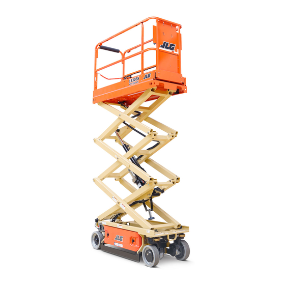
JLG 1930ES Operation And Safety Manual
Hide thumbs
Also See for 1930ES:
- Service maintenance manual (212 pages) ,
- Operation and safety manual (136 pages) ,
- Operation & safety manual (50 pages)

Related Manuals for JLG 1930ES


Summary of Contents for JLG 1930ES
- Page 1 Operation and Safety Manual Original Instructions, Keep this manual with the machine at all times. Models 1930ES/2030ES/ 2630ES/ 2646ES/3246ES ANSI P/N - 3121165 ® May 1, 2013...
- Page 2 IT IS A GOOD PRACTICE TO AVOID PRESSURE-WASHING ELECTRICAL/ELECTRONIC COMPONENTS. SHOULD PRESSURE-WASHING BE UTILIZED TO WASH AREAS CONTAINING ELECTRICAL/ELECTRONIC COMPONENTS, JLG INDUSTRIES, INC. RECOMMENDS A MAXIMUM PRESSURE OF 750 PSI (52 BAR) AT A MINIMUM DIS- TANCE OF 12 INCHES (30.5 CM) AWAY FROM THESE COMPONENTS. IF ELECTRICAL/ELECTRONIC COMPO- NENTS ARE SPRAYED, SPRAYING MUST NOT BE DIRECT AND BE FOR BRIEF TIME PERIODS TO AVOID HEAVY SATURATION.
- Page 3 INDICATES INFORMATION OR A COMPANY POLICY THAT RELATES AVOIDED, COULD RESULT IN SERIOUS INJURY OR DEATH. THIS DECAL DIRECTLY OR INDIRECTLY TO THE SAFETY OF PERSONNEL OR PRO- WILL HAVE AN ORANGE BACKGROUND. TECTION OF PROPERTY. – JLG Lift – 3121165...
- Page 4 JLG INDUSTRIES, INC. MUST BE NOTIFIED IMMEDIATELY IN ALL or Your Local JLG Office (See addresses on manual rear cover) INSTANCES WHERE JLG PRODUCTS HAVE BEEN INVOLVED IN AN ACCI- DENT INVOLVING BODILY INJURY OR DEATH OF PERSONNEL OR In USA:...
-
Page 5: Revision Log
Revised ......September 28, 2012 Revised ......May 1, 2013 – JLG Lift – 3121165... -
Page 6: Table Of Contents
MDI Description ......3-10 Operator Responsibility ..... 2-1 3121165 – JLG Lift –... - Page 7 4.12 TOWING ........4-13 Remote Electric Brake Release....4-13 – JLG Lift – 3121165...
- Page 8 Oil Check Procedure (1) ....6-12 Lower (2) & Upper Slide Pads (3) ... . 6-13 3121165 – JLG Lift –...
- Page 9 3-5. Decal Location - 1930ES - Sht. 2 of 2 ... 3-12 Platform Capacities ......6-5 3-6.
-
Page 10: Section 1 - Safety Precautions
In order to promote questions with regard to safety, training, inspection, mainte- proper machine usage, it is mandatory that a daily routine is nance, application, and operation, please contact JLG Industries, established based on the content of this manual. A mainte- Inc. (“JLG”). -
Page 11: Pre-Operation
JLG. of this manual, contact JLG Industries, Inc. • All operating personnel must be familiar with the emer- gency controls and emergency operation of the machine as specified in this manual. -
Page 12: Machine Inspection
• Check the work area for hazardous locations. Do not oper- ate the machine in hazardous environments unless approved for that purpose by JLG. MODIFICATION OR ALTERATION OF AN AERIAL WORK PLATFORM SHALL BE MADE ONLY WITH PRIOR WRITTEN PERMISSION FROM THE MANUFACTURER. - Page 13 50,000 volts. One foot additional clearance is required for every additional 30,000 volts or less. – JLG Lift – 3121165...
-
Page 14: Minimum Approach Distances (M.a.d.)
Over 350 KV to 500 KV 35 (11) Over 500 KV to 750 KV Over 750 KV to 1000 KV 45 (14) NOTE: This requirement shall apply except where employer, local or governmental regulations are more stringent. 3121165 – JLG Lift –... -
Page 15: Trip And Fall Hazards
SECTION 1 - SAFETY PRECAUTIONS Trip and Fall Hazards • JLG Industries, Inc. recommends that all persons in the plat- form wear a full body harness with a lanyard attached to an authorized lanyard anchorage point while operating this machine. For further information regarding fall protection requirements on JLG products, contact JLG Industries, Inc. -
Page 16: Tipping Hazards
• Never exceed the maximum work load as specified on the platform. Keep all loads within the confines of the platform, unless authorized by JLG. • Keep the chassis of the machine a minimum of 0.6 m (2 ft) from holes, bumps, drop-offs, obstructions, debris, con- cealed holes, and other potential hazards at the ground level. -
Page 17: Crushing And Collision Hazards
• Avoid operating over ground personnel. Warn personnel not to work, stand, or walk under a raised platform. Position barricades on floor as necessary. • During operation, keep all body parts inside platform rail- ing. – JLG Lift – 3121165... -
Page 18: Towing, Lifting, And Hauling
• Always relieve hydraulic pressure from all hydraulic circuits before loosening or removing hydraulic components. • Always disconnect batteries when servicing electrical com- ponents or when performing welding on the machine. 3121165 – JLG Lift –... -
Page 19: Battery Hazards
• Reference the Service and Maintenance Manual for the to batteries only after the batteries are fully charged. weights of critical stability items. MODIFICATION OR ALTERATION OF AN AERIAL WORK PLATFORM SHALL BE MADE ONLY WITH PRIOR WRITTEN PERMISSION FROM THE MANUFACTURER. 1-10 – JLG Lift – 3121165... -
Page 20: Section 2 - User Responsibilities, Machine Preparation & Inspection
5. Enough knowledge of the mechanical operation of the machine to recognize a malfunction or potential malfunction. 6. The safest means to operate the machine where over- head obstructions, other moving equipment, and obstacles, depressions, holes, drop-offs. 3121165 – JLG Lift –... -
Page 21: Inspection And Maintenance Table
PREPARATION, INSPECTION, AND MAINTENANCE The table below covers the periodic machine inspections and maintenance recommended by JLG Industries, Inc. Consult local reg- ulations for further requirements for aerial work platforms. The frequency of inspections and maintenance must be increased as necessary when the machine is used in a harsh or hostile environment, if the machine is used with increased frequency, or if the machine is used in a severe manner. -
Page 22: Pre-Start Inspection
Make sure all illegible decals and placards are cleaned or replaced. 4. Operation and Safety Manuals – Make sure a copy of the Operator and Safety Manual, AEM Safety Manual (ANSI markets only), and ANSI Manual of Responsibili- 3121165 – JLG Lift –... -
Page 23: Function Check
Drive the machine on a grade, not to exceed the when the Emergency Stop Button is depressed. rated gradeability, and stop to ensure the brakes hold. b. Check the tilt indicator light to ensure proper operation. The light should be illuminated when tilted. – JLG Lift – 3121165... -
Page 24: High Drive Speed Cutout Height
2030ES 66 in. 1.7 m 18.75 (Full) 2630ES 76 in. 1.9 m 1930ES 2646ES 76 in. 1.9 m 3246ES 76 in. 1.9 m 20 (Full) 2030ES 25.4 (Full) 2630ES 26 (Full) 2646ES 31.75 (Full) 3246ES 3121165 – JLG Lift –... - Page 25 SECTION 2 - USER RESPONSIBILITIES, MACHINE PREPARATION & INSPECTION Figure 2-1. Daily Walk-Around Inspection - Sheet 1 of 2 – JLG Lift – 3121165...
- Page 26 15. Sizzor Arms, Pivot Pins and Sliding Wear Pads (Not ual in storage box. Shown) - See Note 2. Steer Cylinder - See Note 16. Platform/Handrail Installation (Not Shown) - See Note Figure 2-2. Daily Walk-Around Inspection - Sheet 2 of 2 3121165 – JLG Lift –...
- Page 27 SECTION 2 - USER RESPONSIBILITIES, MACHINE PREPARATION & INSPECTION SWITCHES THROUGHOUT MACHINE NOTE: Item 1 - location for machines prior to S/N’s: 1930ES - USA built - S/N 0200150266 - Belgium built - S/N 1200007882 2030ES/2630ES - USA built - S/N 0200152825 - Belgium built - S/N 1200008481...
- Page 28 2. Rotary Angle Switch NOTE: Item 1 - location for machines from S/N’s to present: 1930ES - USA built - S/N 0200151266 - Belgium built - S/N 1200007882 2030ES/2630ES - USA built - S/N 0200152825 - Belgium built - S/N 1200008481...
- Page 29 SECTION 2 - USER RESPONSIBILITIES, MACHINE PREPARATION & INSPECTION NOTES: 2-10 – JLG Lift – 3121165...
-
Page 30: General
It is important that the machine to recognize a malfunction or potential all personnel who are assigned to and responsible for the opera- malfunction. tion and maintenance of the machine undergo a thorough 3121165 – JLG Lift –... -
Page 31: Training Supervision
JLG Distributor before proceeding. 1. Machine is positioned on a smooth, firm and level sur- NOTE: Manufacturer or Dealer will provide qualified persons for face. -
Page 32: Stability
With the power select switch This machine, as originally manufactured by JLG and operated in the center off position, power is shut off to both within its rated capacity on a smooth, firm and level supporting platform and ground controls. -
Page 33: Ground Control Station
Figure 3-2. Battery Charger Status operator an accurate read on the status of the battery charger. a. Green = Charge complete b. Yellow = Charging in process c. Red = Charging abnormal – JLG Lift – 3121165... -
Page 34: Platform Control Station
8. Lift/Drive Select Switch 9. Horn 10. Steer Switch 11. Controller 12. Emergency Stop Switch 13. Trigger Switch NOTE: *There is no light equipped on a single capacity ANSI machine. Figure 3-3. Platform Control Station 3121165 – JLG Lift –... - Page 35 2. Outdoor (CE) / Zone B Capacity (ANSI/AUS) - This indi- this switch is used to select either indoor or outdoor cator light will be illuminated when the Outdoor (CE) capacity zone. or Zone B (ANSI/AUS) capacity is selected. – JLG Lift – 3121165...
- Page 36 The speed on all selected func- form is elevated. tions is proportionally controlled by the distance of travel of the hand controller. The thumb-operated 3121165 – JLG Lift –...
- Page 37 DO NOT “LOWER” WITHOUT COMPLETELY RETRACTING THE PLATFORM EXTENSION. DO NOT OPERATE MACHINE IF HIGH DRIVE SPEED OPERATES WHEN PLAT- FORM IS RAISED ABOVE THE STOWED POSITION. – JLG Lift – 3121165...
-
Page 38: Mdi (Multifunction Digital Indicator)
SECTION 3 - USER RESPONSIBILITIES AND MACHINE CONTROLS MDI (MULTIFUNCTION DIGITAL INDICATOR) 1. Battery Compartment 2. Diagnostic Trouble Code LCD 3. Wrench Icon (Fault) 4. Fault LED 5. Battery Discharge Indicator (BDI) Figure 3-3. MDI Indicator - Location and Description 3121165 – JLG Lift –... -
Page 39: Mdi Description
• Under normal driving conditions the BDI’s will be illumi- NOTE: For DTC’s and descriptions, refer to Section 4.13, Diagnos- nated. When a DTC exists (other than 00x DTC’s) the BDI tic Trouble Codes (DTC) Check Tables. LEDs will not be illuminated. 3-10 – JLG Lift – 3121165... - Page 40 SECTION 3 - USER RESPONSIBILITIES AND MACHINE CONTROLS Both Both Sides Sides 40 21 27 41 22 12 Figure 3-3. Decal Location - 1930ES- Sheet 1 of 2 3121165 – JLG Lift – 3-11...
- Page 41 SECTION 3 - USER RESPONSIBILITIES AND MACHINE CONTROLS Both Sides 25 23 Figure 3-4. Decal Location - 1930ES - Sheet 2 of 2 3-12 – JLG Lift – 3121165...
- Page 42 SECTION 3 - USER RESPONSIBILITIES AND MACHINE CONTROLS Both Sides Both Sides Both Sides Both Sides 27 41 22 12 14 40 21 38 19 25 23 Figure 3-5. Decal Location - 2030ES & 2630ES - Sheet 1 of 2 3121165 – JLG Lift – 3-13...
- Page 43 SECTION 3 - USER RESPONSIBILITIES AND MACHINE CONTROLS 40 21 27 41 22 Figure 3-6. Decal Location - 2030ES & 2630ES - Sheet 2 of 2 3-14 – JLG Lift – 3121165...
- Page 44 SECTION 3 - USER RESPONSIBILITIES AND MACHINE CONTROLS Both Sides 32 29 Both Sides 40 21 41 22 Both Sides Both Sides 44 15 Figure 3-7. Decal Location - 2646ES & 3246ES - Sheet 1 of 2 3121165 – JLG Lift – 3-15...
- Page 45 SECTION 3 - USER RESPONSIBILITIES AND MACHINE CONTROLS Both Sides Figure 3-8. Decal Location - 2646ES & 3246ES - Sheet 2 of 2 3-16 – JLG Lift – 3121165...
-
Page 46: Decal Location Legend
1703811 1703811 1703814 1703814 1703814 1703814 1703814 1703814 1703814 1703814 1704277 1704277 1704277 1704277 1704277 1704277 1704277 1704277 1703819 1703819 1703819 1703819 1703819 1703819 1703819 1703819 1703822 1703822 1703822 1703822 1703822 1703822 1703822 1703822 3121165 – JLG Lift – 3-17... - Page 47 1705643 1705643 1705643 1705643 1705643 1705643 1705643 (2630ES) 1705644 1705644 1705644 1705644 1705644 1705644 1705644 1705644 (2646ES) 1705645 1705645 1705645 1705645 1705645 1705645 1705645 1705645 (3246ES) 1705646 1705646 1705646 1705646 1705646 1705646 1705646 1705646 3-18 – JLG Lift – 3121165...
- Page 48 1704134 1704134 1704134 1704134 1704134 (2630ES) 1706310 1706310 1706310 1706310 1706310 1706310 1706310 1706310 (2646ES) 1706311 1706312 1706312 1706311 1706311 1706311 1706311 1706311 (3246ES) 1706311 1706312 1706312 1706311 1706311 1706311 1706311 1706311 1705303 1705303 3121165 – JLG Lift – 3-19...
- Page 49 1706053 1701499 1701499 1701499 1701499 1701499 1701499 1701499 1701499 (1930ES) 1001092071 1001092497 1001092071 1001092580 1001092071 1001092071 1001092071 1001092071 1001094359 1001094359 1001094359 1001094359 1001094359 1001094359 1001094359 1001094359 1001146794 1001146795 1001146795 1001146794 1001146794 1001146794 1001146794 1001146794 3-20 – JLG Lift – 3121165...
-
Page 50: Section 4 - Machine Operation
The JLG Scissor Lift has a primary operator Control Station in the platform control station. The switch should be in the off position platform. From this Control Station, the operator can drive and when parking the machine overnight. -
Page 51: Raising
3. If operating from the ground controls, position the lift switch to up and hold until desired elevation is achieved. If operating from the platform controls, select lift function, squeeze and hold the red trigger switch, move the controller backward (up) and hold – JLG Lift – 3121165... -
Page 52: Arm Guards (If Equipped)
The machine is equipped with a mechanically extendable deck, stop lowering and an alarm will sound once it has reached a pre- giving the operator better access to worksites. On the 1930ES/ set height. At this point, the trigger switch and controller must 2030ES/2630ES this extension adds 3 ft (0.9 m) and on the... -
Page 53: Fold-Down Rails
Return drywall gate to the lowered position. AFTER THE RAILS HAVE BEEN FOLDED DOWN, USE EXTREME CAUTION WHEN EXITING AND ENTERING THE PLATFORM. – JLG Lift – 3121165... -
Page 54: Steering
SPECIFIED. REFERENCE FIGURE 4-1., GRADE AND SIDESLOPE. Driving Forward 1. Place power selector switch at ground control station to "Platform." 2. Position emergency stop switch at platform control station to "On" position. 3. Select "Drive" on the drive/lift select switch. 3121165 – JLG Lift –... - Page 55 SECTION 4 - MACHINE OPERATION HORIZONTAL Figure 4-1. Grade and Sideslope – JLG Lift – 3121165...
-
Page 56: Parking And Stowing
DO NOT OPERATE MACHINE FROM THE PLATFORM OR GROUND CONTROLS control station can be secured to it’s mount by placing a WITH THE ANTI-VANDAL COVERS CLOSED AND LOCKED IN PLACE. lock through one or more of the holes located on it’s upper mounting tabs. 3121165 – JLG Lift –... -
Page 57: Battery Charging
The battery charger receptacle is located at the right rear of the seconds. machine near the ground control panel. 3. The batteries are fully charged when green light on 1. Connect the charger to a grounded outlet. the battery charger status panel is illuminated. – JLG Lift – 3121165... -
Page 58: Battery Charger Fault Codes
30 seconds of operation. Once it has been determined that the batteries and connections are not faulty and fault 6 is again displayed after interrupting AC power for at least 10 seconds, the charger must be brought to a qualified service depot. 3121165 – JLG Lift –... -
Page 59: Platform Loading
To store the safety prop, raise the platform, swing the safety prop around and restore it back to its stowed position. 4-10 – JLG Lift – 3121165... -
Page 60: Tie Down/Lift Lugs
LIFTING THE MACHINE FROM THE SIDES USING A FORK TRUCK IS NOT REC- OMMENDED BY JLG. IN THE EVENT THAT THE MACHINE NEEDS TO BE LIFTED FROM THE SIDES CAUTION MUST BE USED TO AVOID JAMMING THE POT HOLE PROTECTION BARS UP AGAINST THE FRAME. -
Page 61: Lifting And Tie Down Diagram
SECTION 4 - MACHINE OPERATION FRONT (ANSI - CSA - CE) FRONT REAR (JAPAN - AUS) Figure 4-3. Lifting and Tie Down Diagram 4-12 – JLG Lift – 3121165... -
Page 62: Towing
1. Chock wheels or secure machine with tow vehicle. the emergency stop switch, or take the ground control 2. Pull the emergency stop switch out and position the keyswitch out of the ground mode position. keyswitch to ground mode. 3121165 – JLG Lift – 4-13... -
Page 63: Mechanical Brake Release
8. After towing is complete, chock wheels and remove 2 dis- engage bolts (3) from disengage holes (4). Insert bolts back into original holes in motor end cap. 9. Reinstall cover (2). Figure 4-4. Manual Disengage 4-14 – JLG Lift – 3121165... -
Page 64: Mechanical Brake Release
AFTER THE MACHINE IS TOWED, THE DISENGAGE BOLTS MUST BE REMOVED FROM THE BRAKE DISENGAGE HOLES. THE BRAKES CANNOT BE ENGAGED Machines, USA built s/n 0200170585 to Present: Machines, Belgium built s/n 1200015159 to Present: 3121165 – JLG Lift – 4-15... -
Page 65: Manual Disengage
FROM THE BRAKE DISENGAGE HOLES. THE BRAKES CANNOT BE ENGAGED WITH THE DISENGAGE BOLTS IN THE BRAKE DISENGAGE HOLES. THIS WILL Figure 4-6. Manual Disengage CAUSE THE MACHINE TO ROLL WHEN PARKED ON AN INCLINE. 4-16 – JLG Lift – 3121165... -
Page 66: Lifting And Tie Down Chart
1930ES 2030ES 73.9 38.5 2030ES 187.7 98.9 38.5 2630ES 73.9 97.8 187.7 2630ES 2646ES 43.8 20.5 82.32 2646ES 209.1 108.6 20.5 43.8 82.32 3246ES 209.1 108.4 3246ES Figure 4-7. Lifting and Tie Down Chart 3121165 – JLG Lift – 4-17... -
Page 67: Diagnostic Trouble Codes (Dtc)
DTCs are sorted in groups by the first two digits, which is also the system distress lamp flash code. To troubleshoot multiple DTCs, start with the DTC with the higher first two digits. If a correction is made during a check, conclude the check by cycling the machine power, using the emergency stop switch. 4-18 – JLG Lift – 3121165... -
Page 68: Help Comments
Error (Displayed on MDI) The MDI is powered, but cannot communi- cate with the control system. • Check the diagnostic connector. Refer problem to a qualified JLG mechanic. 001 EVERYTHING OK The normal help message in platform mode. Displays on the analyzer only. - Page 69 • Check that the elevation angle sensor is securely mounted. • Check that the pothole protection switches are securely mounted. Refer problem to a qualified JLG mechanic. 005 DRIVE & LIFT UP PREVENTED - TILTED Driving is not possible since the platform is •...
-
Page 70: Power-Up
• Check that the PHP switches are securely mounted. hole protection mechanism failed to Refer problem to a qualified JLG mechanic. retract. 008 FUNCTIONS LOCKED OUT - SYSTEM After 2 hours without activity, the control •... -
Page 71: Platform Controls
• Check if the horn switch is damaged, obstructed or jammed. NENTLY SELECTED up in platform mode. Refer problem to a qualified JLG mechanic. 222 FUNCTION PROBLEM - INDOOR / OUT- The indoor / outdoor (zone A / zone B) •... -
Page 72: Ground Controls
2210 TRIGGER CLOSED TOO LONG WHILE IN The trigger switch was closed for more NEUTRAL than five seconds while the joystick was Refer problem to a qualified JLG mechanic. centered. • Check if either function is active, if Yes; 2232 FUNCTION PROBLEM - DRIVE & LIFT... -
Page 73: Function Prevented
• Check that the platform elevation sensor is securely mounted and AGE OUT OF RANGE angle sensor input. undamaged. Refer problem to a qualified JLG mechanic. 252 ELEV ANGLE SENSOR HAS NOT BEEN The elevation angle sensor has not been Refer problem to a qualified JLG mechanic. - Page 74 DESCRIPTION CHECK 257 ELEV PROX PERMANENTLY CLOSED - The elevation proximity switch shows the Refer problem to a qualified JLG mechanic. CHECK PROX AND ANGLE ADJUST- platform to be stowed, while the elevation MENT angle sensor shows the platform to be raised.
-
Page 75: Line Contactor Open Circuit
DESCRIPTION CHECK 311 OPEN CIRCUIT LINE CONTACTOR There is a problem with the line contactor. Refer problem to a qualified JLG mechanic. 312 CONTACTOR DRIVER PERMANENTLY There is a problem with the power module Refer problem to a qualified JLG mechanic. -
Page 76: Ground Output Driver
DESCRIPTION CHECK 331 BRAKE SHORT TO BATTERY A problem has been detected in this func- Refer problem to a qualified JLG mechanic. tion. 332 BRAKE OPEN CIRCUIT A problem has been detected in this func- Refer problem to a qualified JLG mechanic. - Page 77 CHECK 3310 STEER RIGHT OPEN CIRCUIT A problem has been detected in this func- Refer problem to a qualified JLG mechanic. tion. 3311 GROUND ALARM SHORT TO BATTERY A problem has been detected in this func- Refer problem to a qualified JLG mechanic.
-
Page 78: Thermal Limit (Soa)
DESCRIPTION CHECK 33303 NEGATIVE SUPPLY - SHORT TO A problem has been detected in this func- Refer problem to a qualified JLG mechanic. GROUND tion. 33304 RIGHT BRAKE - SHORT TO GROUND A problem has been detected in this func- Refer problem to a qualified JLG mechanic. -
Page 79: Battery Supply
• Check for severely discharged battery, loose cables or for damaged bat- was measured to be out of normal operat- tery; otherwise; 4421 ing range. • Refer problem to a qualified JLG mechanic. 4422 4-30 – JLG Lift – 3121165... -
Page 80: Communication
DESCRIPTION CHECK 661 CANBUS FAILURE - POWER MODULE The control system failed to receive mes- Refer problem to a qualified JLG mechanic. sages from the power module. 662 CANBUS FAILURE - PLATFORM MOD- In platform mode, the control system Refer problem to a qualified JLG mechanic. -
Page 81: Electric Motor
DESCRIPTION CHECK 771 OPEN CIRCUIT DRIVE MOTOR WIRING The power module detected a problem in Refer problem to a qualified JLG mechanic. the drive motors' power circuit wiring. 772 STALLED TRACTION MOTOR OR POWER The power module detected a problem in Refer problem to a qualified JLG mechanic. -
Page 82: Tilt Sensor
DESCRIPTION CHECK 7710 PUMP P HIGH - CHECK POWER CIR- The power module detected a problem in Refer problem to a qualified JLG mechanic. CUITS the drive motors' power circuit wiring. 7711 PUMP P LOW - CHECK POWER CIR- The power module detected a problem in Refer problem to a qualified JLG mechanic. -
Page 83: Platform Load Sense
DESCRIPTION CHECK 821 LSS CELL #1 ERROR A problem has been detected with the load Refer problem to a qualified JLG mechanic. sense system. 822 LSS CELL #2 ERROR A problem has been detected with the load Refer problem to a qualified JLG mechanic. - Page 84 DESCRIPTION CHECK 994 LSS INTERNAL ERROR - DRDY MISSING A problem has been detected with the load Refer problem to a qualified JLG mechanic. FROM A/D sense system. 995 POWER MODULE FAILURE - PERSON- A problem has been detected with the Refer problem to a qualified JLG mechanic.
- Page 85 SECTION 4 - MACHINE OPERATION 9-9 Hardware FAULT MESSAGE DESCRIPTION CHECK 9924 FUNCTIONS LOCKED OUT - MACHINE A new ground board was installed but not Refer problem to a qualified JLG mechanic. NOT CONFIGURED configured. 4-36 – JLG Lift – 3121165...
- Page 86 POWER MODULE FAILURE - INTERNAL A problem has been detected with the Cycle machine power on /off a few times if this doesn’t clear the DTC, 9951 ERROR power module. refer problem to a qualified JLG mechanic. 9952 9953 9954 9955 9956...
- Page 87 SECTION 4 - MACHINE OPERATION NOTES: 4-38 – JLG Lift – 3121165...
-
Page 88: General
CHECK MACHINE DAILY TO MAKE SURE EMERGENCY STOP BUTTON IS IN PLACE AND THAT GROUND CONTROL INSTRUCTIONS ARE IN PLACE AND LEGI- BLE.GROUND CONTROL STATION 3121165 – JLG Lift –... -
Page 89: Emergency Operation
– JLG Lift – 3121165... -
Page 90: Platform Caught Overhead
It is imperative that JLG Industries, Inc. be notified immediately tures or equipment, do not continue operation of the machine of any incident involving a JLG product. Even if no injury or from either the platform or the ground until the operator and all property damage is evident, the Product Safety and Reliability personnel are safely moved to a secure location. - Page 91 SECTION 5 - EMERGENCY PROCEDURES NOTES: – JLG Lift – 3121165...
-
Page 92: Section 6 - General Specifications And Operator Maintenance
The maintenance portion of this section is intended as informa- tion to assist the machine operator to perform daily mainte- nance tasks only, and does not replace the more thorough Preventive Maintenance and Inspection Schedule included in the Service and Maintenance Manual. 3121165 – JLG Lift –... -
Page 93: Operating Specifications
2.5 mph 2.5 mph (4.8 kmh) (4.8 kmh) (4.4 kmh) (4 kmh) (4 kmh) Maximum Wind Speed 28 mph (12.5 m/s) (Depending on model, market, and indoor/outdoor selection, see Table 6-2, Platform Capacities on page 6-5) – JLG Lift – 3121165... - Page 94 90° 90° 90° Outside Steer Angle 69° 73° 73° 67° 67° Electrical System Voltage (DC) Approximate Gross Machine Weight - 4815 lbs (single) 2685 lbs 3830 lbs 4945 lbs 4945 lbs ANSI/CSA 4750 lbs (dual) 3121165 – JLG Lift –...
- Page 95 2257 kg 2257 kg 2155 kg (dual) Ground Clearance with pot hole protection system up 3.5 in (8.9 cm) Ground Clearance with pot hole protection system down 1 in (2.5 cm) .75 in (1.9 cm) – JLG Lift – 3121165...
-
Page 96: Platform Capacities
(454 kg) Zone A 3246ES to 26 ft. 1000 lb 450kg 320 kg 450 kg 320 kg (454 kg) Zone B 3246ES to 32 ft. 700 lb 320kg 320 kg 320 kg 320 kg (317 kg) 3121165 – JLG Lift –... -
Page 97: Dimensional Data
Overall Machine Width Overall Machine Length - Deck Retracted Overall Machine Length - Deck Extended 10.5 10.5 12.4 12.4 Platform Size - Length Platform Size - Width 0.76 Platform Extension Length Wheelbase 73.9 73.9 82.3 82.3 – JLG Lift – 3121165... -
Page 98: Motors
Power: 0.65 Horsepower @ 3750 rpm Amp Hour (Standard Battery) 220 Amp Hydraulic Pump/Electric Motor Assembly (All Models) Amp Hour (Optional High Output Battery) 245 Amp Type: Series Wound Permanent Magnet 24V DC Power: 3kW 3121165 – JLG Lift –... -
Page 99: Capacities
1930ES 2030ES 2630ES 2646ES 3246ES Size 323mm x 100mm 406 mm x 125 mm Max Tire Load 2500 lbs (1134 kg) 4000 lbs (1814 kg) Wheel Bolt Torque 105 - 120 ft lb (142-163 Nm) – JLG Lift – 3121165... -
Page 100: Critical Stability Weights
283 lbs (128 kg) Batteries: (each) 220 Amp 60 lbs (27 kg) 60 lbs (27 kg) 220 Amp (used with Inverter/Charger) 66 lbs (30 kg) 66 lbs (30 kg) 245 Amp 70 lbs (32 kg) 3121165 – JLG Lift –... -
Page 101: Lubrication
SECTION 6 - GENERAL SPECIFICATIONS AND OPERATOR MAINTENANCE Lubrication NOTE: Aside from JLG recommendations, it is not advisable to mix oils of different brands or types, as they may not contain the same required additives or be of comparable viscosities. -
Page 102: Operator Maintenance
SECTION 6 - GENERAL SPECIFICATIONS AND OPERATOR MAINTENANCE OPERATOR MAINTENANCE 1. Hydraulic Oil 2. Lower Slide Pads 3. Upper Slide Pads Figure 6-1. Lubrication Diagram 3121165 – JLG Lift – 6-11... -
Page 103: Oil Check Procedure (1)
5. To check the oil level, lower platform so it rests on the NOTE: The 2630ES/2646ES/3246ES platforms will have to be safety prop. raised higher than the 1930ES and 2030ES in order to access the oil plug. THERE MAY BE UP TO 10 PSI OF PRESSURE IN THE TANK. -
Page 104: Lower (2) & Upper Slide Pads (3)
(1, 2). Refer to cycle the scissor arms several times and refer to steps 3 Figure 6-2., Lower Slide Pad Channel. and 4 to recheck oil level. 3121165 – JLG Lift – 6-13... -
Page 105: Lower Slide Pad Channel
Figure 6-3. Upper Slide Pad Channel NOTE: Recommended lubricating intervals are based on machine operations under normal conditions. For machines used in multi-shift operations and/or exposed to hostile environments or conditions, lubrication fre- quencies must be increased accordingly. 6-14 – JLG Lift – 3121165... -
Page 106: Tires And Wheels
RATION OF WHEEL FROM THE AXLE. BE SURE TO USE ONLY THE NUTS MATCHED TO THE CONE ANGLE OF THE WHEEL. 3. The tightening of the nuts should be done in stages. Fol- lowing the recommended sequence, tighten nuts per wheel torque. 3121165 – JLG Lift – 6-15... -
Page 107: Wheel Torque Chart
The vibration total value to which the hand-arm system is subjected does not exceed 2,5 m/s2. The highest root mean square value of weighted acceleration to which the whole body is subjected does not exceed 0,5 m/s2. 6-16 – JLG Lift – 3121165... -
Page 108: Inspection And Repair Log
SECTION 7 - INSPECTION AND REPAIR LOG SECTION 7. INSPECTION AND REPAIR LOG Machine Serial Number ______________________________________ Table 7-1. Inspection and Repair Log Date Comments 3121165 – JLG Lift –... - Page 109 SECTION 7 - INSPECTION AND REPAIR LOG Table 7-1. Inspection and Repair Log Date Comments – JLG Lift – 3121165...
Need help?
Do you have a question about the 1930ES and is the answer not in the manual?
Questions and answers