
Related Manuals for Kuka KR 30 HA


Summary of Contents for Kuka KR 30 HA
- Page 1 ROBOT KR 30, 60 HA with KR C4 Assembly Instructions Issued: 20 May 2015 Version: 02 MA KR 30, 60 HA, KR C4 04.11.02 en 1 of 122...
- Page 2 Copyright 2015 KUKA Roboter GmbH Zugspitzstrasse 140 D- -86165 Augsburg This documentation or excerpts therefrom may not be reproduced or disclosed to third parties without the express permission of the publishers. Other functions not described in this documentation may be operable in the controller. The user has no claims to these functions, however, in the case of a replacement or service work.
-
Page 3: Table Of Contents
Contents Introduction ........... . . Robot documentation . - Page 4 Assembly Instructions 5.5.5 Labeling on the industrial robot ..........Safety measures .
- Page 5 11.3 Safety data sheet for Optigear Synthetic RO 150 oil ....... . 11.4 Safety data sheet for Microlube GL 261 lubricant .
- Page 6 Assembly Instructions MA KR 30, 60 HA, KR C4 04.11.02 en 6 of 122...
-
Page 7: Introduction
Introduction Valid for KR 30 HA KR 60 HA KR 60 L45 HA KR 60 L30 HA with KR C4 Introduction Robot documentation The documentation of this robot comprises the following parts: Assembly instructions for KR 30, 60 HA, KR C4 Parts catalog on storage medium Each of these parts is a separate document that is attached to the robot. - Page 8 Assembly Instructions MA KR 30, 60 HA, KR C4 04.11.02 en 8 of 122...
-
Page 9: Purpose
Notice! Deviations from the operating conditions specified in the technical data or the use of special functions or applications can lead to premature wear. KUKA Ro- boter GmbH must be consulted. MA KR 30, 60 HA, KR C4 04.11.02 en... -
Page 10: Target Group
Information! For optimal use of our products, we recommend that our customers take part in a course of training at KUKA College. Information about the training program can be found at www.kuka.com or can be obtained directly from our subsidiaries. -
Page 11: Product Description
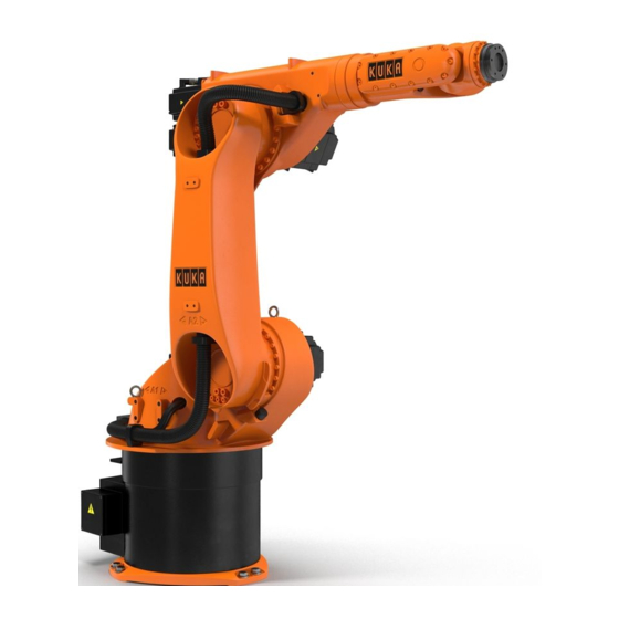
General The industrial robot consists of the manipulator (= robot arm and electrical installations), con- trol cabinet, teach pendant (KUKA smartPAD) and connecting cables (Fig. 1). The manipu- lator is dealt with in this document. The control cabinet, teach pendant and connecting cables are described in separate docu- mentation. -
Page 12: Wrist
Assembly Instructions Wrist The manipulator is equipped with a triple--axis in--line wrist (Fig. 2) for a payload of 30, 45 or 60 kg, depending on the type. The wrist is fastened onto the arm via the flange (4). The axes 6, 5, 4 are driven by shafts (1, 2, 3). An end effector can be attached to the mounting flange (5) of axis 6. -
Page 13: Arm
Product description (continued) The arm assembly (Fig. 3/2) embodies the driven element of axis 3 of the manipulator. The arm is flange--mounted to the side of the link arm (7) through a gear unit with integrated bear- ings and is driven by main axis motor unit A3 (6). The swivel axis (3) of the arm has been so selected that with the rated payload there is no need for an additional counterweight to balance the masses on the arm. -
Page 14: Wrist Axis Motor Units A4 To A6
Assembly Instructions 3.3.1 Wrist axis motor units A4 to A6 The wrist axes are driven by three motor units. These are fastened to the arm (Fig. 4/4) by means of screws. Motor units A4 (3) and A5 (1) are of the same design and drive the respec- tive wrist axes via toothed belts and shafts. -
Page 15: Link Arm
Product description (continued) Link arm The link arm (Fig. 5/1) is the driven element of axis 2. It pivots about rotational axis 2 (3) through an effective software range from +35° to --135° ⎯ referred to the zero position of axis 2, which corresponds to the horizontal position of the link arm in Fig. - Page 16 Assembly Instructions Reference notch A3 Rotational axis 2 Gear unit A3 Link arm Gear unit A2 Rotational axis 3 Gauge cartridge A2 Fig. 6 Structure of link arm MA KR 30, 60 HA, KR C4 04.11.02 en 16 of 122...
-
Page 17: Main Axis Motor Units A1 To A3
Product description (continued) 3.4.1 Main axis motor units A1 to A3 The robot axes 1, 2 and 3 are driven by motor units as shown in Fig. 7. Each motor unit for the main axis drives consists of a brushless AC servomotor (1) with a permanent--magnet single--disk brake and hollow--shaft resolver (2), both integrated. -
Page 18: Rotating Column
Rotating column Special reduction gear unit Base frame Main axis motor unit A2 Zero position A1 Fig. 8 Rotating column with turning range (shown here: KR 30 HA) MA KR 30, 60 HA, KR C4 04.11.02 en 18 of 122... -
Page 19: Base Frame
Product description (continued) The main axis motor unit for axis 1 (Fig. 9/3) is installed in the rotating column with a special reduction gear unit (4), and the main axis motor unit for axis 2 (1) is mounted on the side of the rotating column with its special reduction gear unit (2). -
Page 20: Working Range Limitation For A1 To A3
Assembly Instructions Special reduction gear unit A1 7 Junction box Cover 8 Cover Base frame housing 9 Bracket Attachment holes (6x) 10 MFH, multi- -function housing Base flange 11 Reference notch Locating boreholes (2x) Fig. 10 Structure of base frame Working range limitation for A1 to A3 Mechanical stops for task--related limitation of the respective working range for axes 1 to 3 can be supplied as the “Working range limitation”... -
Page 21: Working Range Monitoring For A1 And A2
Product description (continued) Working range monitoring for A1 and A2 Axes 1 and 2 can be equipped with position switches and slotted rings to which adjustable cams are attached (see documentation “Working Range Monitoring”). This allows the posi- tion of the manipulator to be continuously monitored. Up to three sectors of the movement range can be monitored on axis 1, and a maximum of one sector on axis 2. - Page 22 Assembly Instructions MA KR 30, 60 HA, KR C4 04.11.02 en 22 of 122...
-
Page 23: Technical Data
Technical data Technical data Information! This description applies analogously to all of the industrial robots listed in Chapter 1, regardless of the variant or model shown in the illustrations. General The industrial robots are six--axis manipulators for installation on the floor or on the ceiling. They are suitable for all continuous--path controlled tasks. - Page 24 Assembly Instructions Base frame In- -line wrist Connecting cables Link arm Control cabinet (see Rotating column separate documentation) Fig. 11 Principal robot components MA KR 30, 60 HA, KR C4 04.11.02 en 24 of 122...
-
Page 25: Principal Data
Technical data (continued) Principal data Type KR 30 HA KR 60 HA KR 60 L45 HA KR 60 L30 HA Number of axes 6 (Fig. 13) Load limits see following table and Fig. 12 Robot type KR 60 L45 KR 60 L30... - Page 26 Assembly Instructions KR 30 HA D In- -line wrist, rated payload 30 kg Axis Range of motion, Speed software--limited ±185˚ 140˚/s +35˚ 126˚/s --135˚ +158˚ 140˚/s --120˚ ±350˚ 260˚/s ±119˚ 245˚/s ±350˚ 322˚/s KR 60 HA D In- -line wrist, rated payload 60 kg...
- Page 27 Technical data (continued) KR 60 L30 HA D In- -line wrist, rated payload 30 kg Axis Range of motion, Speed software--limited ±185˚ 128˚/s +35˚ 102˚/s --135˚ +158˚ 128˚/s --120˚ ±350˚ 260˚/s ±119˚ 245˚/s ±350˚ 322˚/s Fig. 13 Rotational axes and their directions of rotation MA KR 30, 60 HA, KR C4 04.11.02 en 27 of 122...
- Page 28 Fig. 18 and Fig. 19. Working envelope The shape and dimensions of the working envelope may be noted from Fig. 18 and Fig. 19. Volume of working envelope KR 30 HA approx. 27.24 m KR 60 HA approx. 27.24 m KR 60 L45 HA approx.
- Page 29 DIN EN 60721--3--3, Class 3K3 Sound level < 75 dB (A) outside the working envelope (Fig. 18 and Fig. 19) Color Manipulator Manipulator overall: KUKA --Orange 2567 Motors: Black (RAL 9005) Cover A1 Black (RAL 9005) Plates see Fig. 22 to Fig. 30.
- Page 30 30 kg KR 30 HA Lz (mm) KR 60 L30 HA Fig. 14 Load center of gravity P and loading curves for KR 30 HA; KR 60 L30 HA MA KR 30, 60 HA, KR C4 04.11.02 en 30 of 122...
- Page 31 + Ly Lz = 150 mm) 18 kgm CAUTION: The mass inertia must be - -X verified using KUKA Load. It is imperative for the load data to be - -Z entered in the controller! - -Y Load center of gravity...
- Page 32 + Ly Lz = 150 mm) 13.5 kgm CAUTION: The mass inertia must be - -X verified using KUKA Load. It is - -Z imperative for the load data to be entered in the controller! - -Y Load center of gravity...
- Page 33 Technical data (continued) Mounting flange DIN/ISO mounting flange (Fig. 17). The mounting flange is depicted with axes 4 and 6 in the zero position. The sym- indicates the position of the locating element (bush- ing). M8 screws of grade 10.9 are to be used for attaching payloads.
- Page 34 Assembly Instructions IMPORTANT: The interference radius (safe area) lies approx. 181 mm beyond the reference point for the working envelope. 820, 1020, 1220 1218 1362 1446 1084 2033 1281 2230 1480 2429 NOTE: The supplementary load center of gravity must be located as close as possible to rotational axis 3 and to line a in Fig.
- Page 35 Technical data (continued) ---185˚ KR 30 HA R=2033 KR 60 HA R=2033 KR 60 L45 HA R=2230 KR 60 L30 HA R=2429 R=181 mm +185˚ IMPORTANT: The interference radius (safe area) lies approx. 181 mm beyond the reference point for the working envelope.
- Page 36 Assembly Instructions View Y from Fig. 18 Center A 3 Support brackets for suppl. load (2x) Max. dimension for suppl. load Fig. 20 Attachment holes for supplementary load MA KR 30, 60 HA, KR C4 04.11.02 en 36 of 122...
- Page 37 6 850 Nm rmax r normal Total mass robot total load for type 665 kg 65 kg KR 30 HA 665 kg 95 kg KR 60 HA 671 kg 80 kg KR 60 L45 HA 679 kg 65 kg KR 60 L30 HA Fig.
- Page 38 Assembly Instructions Fig. 22 Plates on robot (see also Fig. 23 to Fig. 30) Transportstellung: Transport position: Position de transport: 0° --- 135° +158° 0° +90° ACHTUNG! WARNING! ATTENTION! Vor dem Lösen der The robot must be Le robot doit être Fundamentbefesti- amené...
- Page 39 Technical data (continued) ACHTUNG! WARNING! ATTENTION! Vor dem Entfernen des Motors Roboterachse gegen Kippen sichern! Only remove motor when robot axis is secu- red! Avant démontage du moteur bloquer l’axe concerné! Artikel--Nr. 00--118--545 D/GB/F Fig. 24 Instructions for safeguarding against toppling of A2 and A3 Roboter GmbH Zugspitzstraße 140 86165 Augsburg.Germany...
- Page 40 Assembly Instructions ACHTUNG! WARNING! ATTENTION! Vor Aufstellung, Inbetriebnahme, Montage-- und Wartungsarbeiten die Betriebsanleitung und Sicherheitshinweise lesen und beachten! Before installation, start--up, maintenance or disassembling read and follow the safety directions and operating instructions! Avant installation, mise en service, réparation et maintenance veuillez lire les châpitres correspondants du manuel ainsi que les consignes de sécurité...
- Page 41 Technical data (continued) On all motors....................................................................Fig. 29 Drive motor rating plate 00--104--232 3x on base frame Fig. 30 Danger zone MA KR 30, 60 HA, KR C4 04.11.02 en 41 of 122...
- Page 42 Assembly Instructions MA KR 30, 60 HA, KR C4 04.11.02 en 42 of 122...
-
Page 43: Safety
Notice! This “Safety” chapter refers to a mechanical component of an industrial robot. If the mechanical component is used together with a KUKA robot controller, the “Safety” chapter of the operating instructions or assembly instructions of the robot controller must be used! This contains all the information provided in this “Safety”... -
Page 44: Liability
No modifications may be carried out to the industrial robot without the authorization of KUKA Roboter GmbH. Additional components (tools, software, etc.), not supplied by KUKA Ro- boter GmbH, may be integrated into the industrial robot. -
Page 45: Ec Declaration Of Conformity And Declaration Of Incorporation
Safety (continued) Misuse Any use or application deviating from the intended use is deemed to be impermissible mis- use. This includes e.g.: Transportation of persons and animals Use as a climbing aid Operation outside the permissible operating parameters Use in potentially explosive environments Operation without additional safeguards Outdoor operation Underground operation... -
Page 46: Terms Used
Test mode, Manual High Velocity (> 250 mm/s permissible) External axis Motion axis which is not part of the manipulator but which is controlled using the robot controller, e.g. KUKA linear unit, turn--tilt table, Posiflex. MA KR 30, 60 HA, KR C4 04.11.02 en 46 of 122... -
Page 47: Personnel
Safety (continued) Personnel The following persons or groups of persons are defined for the industrial robot: User Personnel Notice! All persons working with the industrial robot must have read and understood the industrial robot documentation, including the safety chapter. User The user must observe the labor laws and regulations. -
Page 48: Workspace, Safety Zone And Danger Zone
Assembly Instructions Operator The operator must meet the following preconditions: The operator must be trained for the work to be carried out. Work on the industrial robot must only be carried out by qualified personnel. These are people who, due to their specialist training, knowledge and experience, and their famil- iarization with the relevant standards, are able to assess the work to be carried out and detect any potential hazards. -
Page 49: Overview Of Protective Equipment
If the manipulator or an external axis hits an obstruction or a mechanical end stop or axis range limitation, this can result in material damage to the industrial robot. The manipulator must be taken out of operation and KUKA Roboter GmbH must be consulted before it is put back into operation. -
Page 50: Mechanical Axis Range Limitation (Optional)
This increases personal safety and protection of the system. Information! This option is not available for all robot models and not for the KR C4. Information on specific robot models can be obtained from KUKA Roboter GmbH. 5.5.4 Options for moving the manipulator without drive energy... - Page 51 Information about the options available for the various robot models and about how to use them can be found in the assembly and operating instructions for the robot or re- quested from KUKA Roboter GmbH. Notice! Moving the manipulator without drive energy can damage the motor brakes of the axes concerned.
-
Page 52: Labeling On The Industrial Robot
Assembly Instructions 5.5.5 Labeling on the industrial robot All plates, labels, symbols and marks constitute safety--relevant parts of the industrial robot. They must not be modified or removed. Labeling on the industrial robot consists of: Identification plates Warning labels Safety symbols Designation labels Cable markings Rating plates... - Page 53 Safety (continued) KCP/smartPAD The user must ensure that the industrial robot is only operated with the KCP/smartPAD by authorized persons. If more than one KCP/smartPAD is used in the overall system, it must be ensured that each device is unambiguously assigned to the corresponding industrial robot. They must not be interchanged.
-
Page 54: Transportation
External axis (optional) The prescribed transport position of the external axis (e.g. KUKA linear unit, turn--tilt table, etc.) must be observed. Transportation must be carried out in accordance with the operating instructions or assembly instructions of the external axis. -
Page 55: Manual Mode
Safety (continued) Function test The following tests must be carried out before start--up and recommissioning. It must be ensured that: The industrial robot is correctly installed and fastened in accordance with the specifica- tions in the documentation. There are no foreign bodies or loose parts on the industrial robot. All required safety equipment is correctly installed and operational. -
Page 56: Automatic Mode
Assembly Instructions If the setup work has to be carried out inside the safeguarded area, the following must be taken into consideration: In Manual Reduced Velocity mode (T1): If it can be avoided, there must be no other persons inside the safeguarded area. If it is necessary for there to be several persons inside the safeguarded area, the following must be observed: Each person must have an enabling device. - Page 57 Faulty components must be replaced using new components with the same article numbers or equivalent components approved by KUKA Roboter GmbH for this purpose. Cleaning and preventive maintenance work is to be carried out in accordance with the operat- ing instructions.
-
Page 58: Decommissioning, Storage And Disposal
Assembly Instructions Hazardous substances The following safety measures must be carried out when handling hazardous substances: Avoid prolonged and repeated intensive contact with the skin. Avoid breathing in oil spray or vapors. Clean skin and apply skin cream. Notice! To ensure safe use of our products, we recommend that our customers regularly request up- -to- -date safety data sheets from the manufacturers of hazardous sub- stances. -
Page 59: Applied Norms And Regulations
Safety (continued) Applied norms and regulations Name Definition Edition Machinery Directive: 2006/42/EC 2006 Directive 2006/42/EC of the European Parliament and of the Council of 17 May 2006 on machinery, and amending Directive 95/16/EC (recast) EMC Directive: 2004 2004/108/EC Directive 2004/108/EC of the European Parliament and of the Council of 15 December 2004 on the approximation of the laws of the Member States relating to electromagnetic compatibility and repealing Directive 89/336/EEC... - Page 60 Assembly Instructions MA KR 30, 60 HA, KR C4 04.11.02 en 60 of 122...
-
Page 61: Transportation
Transportation Transportation Information! This description applies analogously to all of the industrial robots listed in Chapter 1, regardless of the variant or model shown in the illustrations. Caution! If the manipulator is transported by fork lift truck, the forks must be placed in the fork slots. - Page 62 Assembly Instructions Fig. 32 Transport position With fork lift truck (Fig. 34, right--hand side) Caution! If the manipulator is transported by fork lift truck, the forks must be placed in the fork slots. It is forbidden to pick up the manipulator in any other way using a fork lift truck! 122.5 117.5...
- Page 63 Transportation (continued) Fig. 34 Transporting floor- -mounted and ceiling- -mounted manipulators If the manipulator is to be transported away from its site of operation, the following is to be observed: Warning! Turn the main switch on the robot control cabinet to “OFF” and secure it with a padlock to prevent unauthorized persons from switching it on again.
- Page 64 Assembly Instructions Fig. 35 Transport position for floor- -mounted manipulators * All angles are specified relative to the electrical 1309 “zero position” or to the KCP display. 1498 1685 KR 30, 60 HA, without arm extension 200 mm arm extension 400 mm arm extension 135°...
-
Page 65: Installation, Connection
Installation, connection Installation, connection Information! This description applies analogously to all of the industrial robots listed in Chapter 1, regardless of the variant or model shown in the illustrations. General Caution! Observe Chapter 5, “Safety”! With all work involving the connection of the manipulator (and of the control cabinet), the control cabinet documentation “Initial Start- -up”... -
Page 66: Information For Planning
Static axis positions, e.g. continuous vertical position of a wrist axis. If one or more of these conditions are to apply during operation of the kinematic system, KUKA Roboter GmbH must be consulted. MA KR 30, 60 HA, KR C4 04.11.02 en... -
Page 67: Principal Loads
6 850 Nm rmax r normal Total mass robot total load for type 665 kg 65 kg KR 30 HA 665 kg 95 kg KR 60 HA 671 kg 80 kg KR 60 L45 HA 679 kg 65 kg KR 60 L30 HA Fig. -
Page 68: Mounting Variants
Assembly Instructions Mounting variants The manipulator can be installed on the floor or on the ceiling. The mounting variants 1 to 3 are for installing the manipulator on the floor and variants 2 and 3 are for ceiling mounting: Variant 1, mounting base with centering, see Section 7.4.1. Fig. - Page 69 Installation, connection (continued) Variant 3, adapter plate; see Section 7.4.3 Fig. 40 Adapter plate If the manipulator is to be installed on the floor, being directly mounted on a concrete base, all pertinent construction specifications must be observed concerning the grade of concrete and the load--bearing capacity of the ground when preparing the concrete foundation.
- Page 70 Assembly Instructions Fig. 41 Orientation of working envelope and concrete foundation MA KR 30, 60 HA, KR C4 04.11.02 en 70 of 122...
-
Page 71: Variant 1, Mounting Base With Centering
Installation, connection (continued) 7.4.1 Variant 1, mounting base with centering Features: For floor--mounted manipulators only. Manipulator installed on the concrete foundation. Manipulator fastened by means of nine chemical anchors. Notice! When using chemical anchors (resin- -bonded anchors), only resin capsules and anchors (threaded rods) from the same manufacturer may be used. - Page 72 Assembly Instructions (5) If necessary, determine the differences in level. If large differences in level are present, steps (6) to (9) must be followed. (6) Apply leveling compound (Fig. 43/2) to the concrete foundation (4) or the underside of the bedplates. Information! “Knauf leveling compound”, for example, is a suitable compound for this purpose.
- Page 73 Installation, connection (continued) (13) Allow the resin to cure. The curing time is as follows: Temperature Time: +20 °C (293 K) 20 minutes +10 °C (283 K) 30 minutes 0 °C (273 K) 1 hour --5 °C (268 K) 5 hours (14) Mount the hexagon nuts (6) together with washers and tighten the hexagon nuts with a torque wrench in diagonally opposite sequence, increasing the tightening torque to the specified value in several stages (M...
-
Page 74: Variant 2, Machine Frame Mounting
Assembly Instructions 7.4.2 Variant 2, machine frame mounting Features: For floor--mounted and ceiling--mounted manipulators. Manipulator installed on a steel structure prepared by the customer, on a steel pedestal or on a linear unit of the KL 1500 series. Manipulator fastened by means of six M20x55 ISO 4017 hexagon bolts. Installation (1) Prepare the mounting surfaces (Fig. - Page 75 Installation, connection (continued) 16° 30° (147.5) 120° 3x 120° (=360°) 0.1 A Fig. 45 Fastening the manipulator, variant 2 The steel substructure is now ready for the manipulator to be installed. Install the manipulator in accordance with the procedures given in Section 7.5.1. MA KR 30, 60 HA, KR C4 04.11.02 en 75 of 122...
-
Page 76: Variant 3, Adapter Plate
Assembly Instructions 7.4.3 Variant 3, adapter plate Features: For floor--mounted and ceiling--mounted manipulators. Manipulator installed on steel structure or a KUKA linear unit. Easy removal and installation with optimum repeatability of the installation posi- tion. Accessory: Machine frame mounting Information! The adapter plate is mounted and screwed onto a substructure that is prepared by the user. -
Page 77: Connection
Please observe Section 7.1. This description applies to all mounting variants for floor--mounted manipulators only. If the manipulator is to be installed on the floor in an inclined position, KUKA Roboter GmbH must be consulted beforehand. The procedure for installing the manipulator (whether for the first time or as an exchange) is as follows: (1) Check that the locating pins (Fig. - Page 78 +90˚ 0˚ * All angles are specified relative to the electrical 155° “zero position” or to the KCP display. 90° KR 30 HA, 60 HA 135° without arm extension 200 mm arm extension 400 mm arm extension ; 38 ; 85...
- Page 79 Installation, connection (continued) Fig. 49 Installing the manipulator on the floor (4) Insert six M20x55 ISO 4017 hexagon bolts (1) together with spring washers and tighten them with a torque wrench in diagonally opposite sequence, increasing the tightening torque M to the specified value in several stages (M = 370 Nm).
-
Page 80: Ceiling--Mounted Manipulators
Ceiling- -mounted manipulators This description applies to all mounting variants for ceiling--mounted robots only, as de- scribed in Sections 7.4.2 and 7.4.3. If the robot is to be installed in an inclined position, KUKA Roboter GmbH must be consulted beforehand. - Page 81 Installation, connection (continued) (2) Lift the manipulator with a fork lift truck. Fig. 52 Transporting the manipulator Caution! If the manipulator is transported by fork lift truck, the forks must be placed in the slots in the base frame. It is forbidden to pick up the manipulator in any other way using a fork lift truck! (3) Move the manipulator (Fig.
- Page 82 Assembly Instructions Fig. 53 Installing the manipulator on the ceiling (4) Insert six M20x55 ISO 4017 hexagon bolts (1) together with spring washers and tighten them with a torque wrench in diagonally opposite sequence, increasing the tightening torque M to the specified value in several stages (M = 370 Nm).
-
Page 83: Moving The Manipulator Without Drive Energy
Installation, connection (continued) Moving the manipulator without drive energy The release device (optional) can be used for moving the manipulator after an accident or malfunction without drive energy. This option is only for use in exceptional circumstances and emergencies, e.g. for freeing people. Warning! Turn main switch on the manipulator control cabinet to “OFF”... - Page 84 Assembly Instructions MA KR 30, 60 HA, KR C4 04.11.02 en 84 of 122...
-
Page 85: Electrical Installations
Electrical installations Electrical installations Information! This description applies analogously to all of the industrial robots listed in Chapter 1, regardless of the variant or model shown in the illustrations. The electrical installations of the robot (manipulator) form a separate assembly. It includes the “cable set”... - Page 86 Assembly Instructions Cable from Cable from Protective circuit Bolt on Bolt on 00- -182- -118 base frame rotating column Bolt on Bolt on rotating column Motor cable A1 Connector X30/a Control cable A1 Connector X1 00- -181- -928 00- -181- -934 Motor cable A2 Connector X30/b Control cable A2...
- Page 87 Electrical installations (continued) Cable set assembly PE push- -in module Multi- -function housing, MFH Protective circuit Electronic Data Storage EDS Resolver Digital Converter RDC RDC box Fig. 56 Cable set assembly MA KR 30, 60 HA, KR C4 04.11.02 en 87 of 122...
-
Page 88: Cabling Plans And Wiring Diagrams
Assembly Instructions Cabling plans and wiring diagrams Housing YE/GN Type 5/99 4 mm 4 mm 4 mm 1 mm 1 mm 4 mm Power connector Type 07/99 0.25 mm 0.25 mm 0.25 mm 0.25 mm 0.25 mm 0.25 mm 0.25 mm 0.25 mm X02/X1 Fig. - Page 89 Electrical installations (continued) Housing YE/GN Type 4/99 4 mm 4 mm 4 mm 1 mm 1 mm 4 mm Power connector Type 07/99 0.25 mm 0.25 mm 0.25 mm 0.25 mm 0.25 mm 0.25 mm 0.25 mm 0.25 mm X02/X2 Fig.
- Page 90 Assembly Instructions Housing YE/GN Type 10/99 2.5 mm 2.5 mm 2.5 mm 2.5 mm 1 mm 1 mm Power connector 0.25 mm 0.25 mm 0.25 mm 0.25 mm 0.25 mm 0.25 mm 0.25 mm 0.25 mm Type 07/99 X02/X3 Fig. 59 Wiring diagram for drive A3 MA KR 30, 60 HA, KR C4 04.11.02 en 90 of 122...
- Page 91 Electrical installations (continued) Housing YE/GN Type 11/99 1 mm 1 mm 1 mm 1 mm 1 mm 1 mm Power connector Type 07/99 0.25 mm 0.25 mm 0.25 mm 0.25 mm 0.25 mm 0.25 mm 0.25 mm 0.25 mm X02/X4 Fig.
- Page 92 Assembly Instructions Housing YE/GN Type 11/99 1 mm 1 mm 1 mm 1 mm 1 mm 1 mm Power connector Type 07/99 0.25 mm 0.25 mm 0.25 mm 0.25 mm 0.25 mm 0.25 mm 0.25 mm 0.25 mm X02/X5 Fig. 61 Wiring diagram for drive A5 MA KR 30, 60 HA, KR C4 04.11.02 en 92 of 122...
- Page 93 Electrical installations (continued) Housing YE/GN Type 11/99 1 mm 1 mm 1 mm 1 mm 1 mm 1 mm Power connector Type 07/99 0.25 mm 0.25 mm 0.25 mm 0.25 mm 0.25 mm 0.25 mm 0.25 mm 0.25 mm X02/X6 Fig.
- Page 94 Assembly Instructions n.c. TYP06/07 WH/GN TPFO_ P TPFO_ N n.c. n. c. n. c. n. c. WH/OG TPFI_ P TPFI_ N n.c. AWG18 AWG18 24 V/PS buffered n. c. n. c. n. c. Fig. 63 Wiring diagram, RDC internal X31 n.c.
- Page 95 Electrical installations (continued) Bolt Bolt Rotating column Bolt Base frame Push- -in module RDC box Fig. 65 Ground conductor installation, protective circuit MA KR 30, 60 HA, KR C4 04.11.02 en 95 of 122...
- Page 96 Assembly Instructions MA KR 30, 60 HA, KR C4 04.11.02 en 96 of 122...
-
Page 97: Connecting Cables
Connecting cables Connecting cables Information! This description applies analogously to all of the industrial robots listed in Chapter 1, regardless of the variant or model shown in the illustrations. Description Connecting cables are all the cables running between the robot (= manipulator) and the con- trol cabinet (Fig. - Page 98 Assembly Instructions Caution! Before the manipulator is put into operation, the continuity of the ground conductor connection between the control cabinet and the manipulator must be tested with a ground conductor measurement in accordance with DIN EN 60204- -1 and the relevant national regulations. KR C4 Robot control cabinet...
-
Page 99: Routing Of Cables
Connecting cables (continued) Routing of cables The following points must be observed when routing the cables: Bending radius of the cables for fixed installation • Motor cable 150 mm • Control cable 60 mm must be observed Protect cables against exposure to mechanical stress. Route the cables without tension (no tensile forces on the connectors). -
Page 100: Junction Boxes On The Manipulator
Assembly Instructions Junction boxes on the manipulator The plug--in connections on the robot are located on the multi--function housing on the base frame for the motor cable, and on the RDC box for the data cable. The allocation of the junc- tion boxes to the respective connectors for the robot may be noted from Fig. -
Page 101: Connector Panel On The Control Cabinet
Connecting cables (continued) Connector panel on the control cabinet The connector panel (Fig. 69) is accessed by opening the door to the cabinet. The connected cables are routed under the control cabinet to the rear. Fig. 69 Connector panel on the control cabinet MA KR 30, 60 HA, KR C4 04.11.02 en 101 of 122... -
Page 102: Configuration Of The Connecting Cables
Assembly Instructions Configuration of the connecting cables Fig. 70 Motor cable Fig. 71 Data cable M8 ring cable lug 6 Conical spring washer M8 nut 7 Ground plate Conical spring washer 8 PE bolt 8.4 washer 9 Cable lug M8 nut 10 M8 tapped hole Fig. -
Page 103: Wiring Diagrams
Connecting cables (continued) Wiring diagrams n.c. 20/08 TPFO_ P TPFO_ N n. c. n. c. n. c. TPFI_ P TPFI_ N 24 V/PS1 buffered n. c. n. c. Cable gland Cable gland Fig. 73 Data cable X21 MA KR 30, 60 HA, KR C4 04.11.02 en 103 of 122... - Page 104 Assembly Instructions Motor M1 U Motor M1 V Motor M1 W Brake + Brake - - Motor M2 U Motor M2 V Motor M2 W Brake + Brake - - Motor M3 U Motor M3 V Motor M3 W Brake + Brake - - Motor M4 U Motor M4 V...
-
Page 105: Tightening Torques
Tightening torques Tightening torques Information! The following tightening torques are valid for screws and nuts where no other specifica- tions are given. The specified values apply to lightly oiled black (e.g. phosphated) and coated (e.g. mech.galv., zinc flake plating) screws and nuts. Notice! Too high a tightening torque can cause the screws to be overloaded and to frac- ture. - Page 106 Assembly Instructions MA KR 30, 60 HA, KR C4 04.11.02 en 106 of 122...
-
Page 107: Consumables, Safety Data Sheets
Consumables, safety data sheets Consumables, safety data sheets 11.1 Safety data sheet for Optitemp RB1 cable grease The following extract from the safety data sheet according to 91/155/EEC must be observed when han- dling Optitemp RB1. Designation of substance/formulation and manufacturer Trade name: Optitemp RB1 Art. - Page 108 Assembly Instructions Handling and storage Handling: No special measures required. Storage: Store product in original container only. Do not store in direct sunlight. Never leave the container open. Technical Instructions on Air Quality Control / Annex E (Class): Water hazard classification: 1 (manufacturer’s classification based on the law of mixtures acc.
- Page 109 The product may only be used for the scope of work specified above; any other use requires prior consultation with KUKA. Using the product for any purpose other than for its designated use could lead to risks which are not described in this document.
-
Page 110: Safety Data Sheet For Optimol Olit Cls Lubricating Grease
Assembly Instructions 11.2 Safety data sheet for Optimol Olit CLS lubricating grease The following extract from the safety data sheet according to 91/155/EEC must be observed when han- dling Optimol Olit CLS. Designation of substance/formulation and manufacturer Trade name: Optimol Olit CLS Art. - Page 111 Consumables, safety data sheets (continued) Handling and storage Handling: No special measures required if handled in accordance with specifications. Storage: Store in a dry, dust--free atmosphere in closed, original containers at temperatures between 10--20 °C. Avoid large variations in temperature! Do not store together with strong oxidizing agents.
- Page 112 The product may only be used for the scope of work specified above; any other use requires prior consultation with KUKA. Using the product for any purpose other than for its designated use could lead to risks which are not described in this document.
- Page 113 Consumables, safety data sheets (continued) 11.3 Safety data sheet for Optigear Synthetic RO 150 oil Designation of substance/formulation and manufacturer Product name: Optigear Synthetic RO 150 SDS no.: 465036 Historical SDS no.: DE- -05254, FR- -465036, SK- -5254 Use of substance or formulation: Lubricant For specific instructions for use, see the corresponding technical data sheet or contact a company representative.
- Page 114 Assembly Instructions First aid measures Eye contact: In case of contact, rinse eyes immediately with plenty of water for at least 15 minutes. If irritation occurs, consult a doctor. Skin contact: Wash affected areas of skin with soap and water, or use suitable cleaning agent. Change clothing and shoes if they become contaminated with product.
- Page 115 Consumables, safety data sheets (continued) Measures after unintended release Personal safety precautions: No measures should be taken that involve a risk to personnel or have not been adequately trained. Evacuate the environment. Refuse access to personnel who are not required or are unprotected. Do not touch or step on any spilled substance. Avoid breathing in any spray or vapors.
- Page 116 Assembly Instructions Exposure limits and personal protective equipment Ingredient name ACGIH TLVs: Base oil – unspecified Limits to monitor: ACGIH (USA). TWA: 5 mg/m 8 hour(s). Form: mineral oil mist STEL: 10 mg/m 15 minute(s). Form: mineral oil mist The ACGIH values are enclosed for information and orientation purposes. Further information can be obtained from your supplier.
- Page 117 Consumables, safety data sheets (continued) 10 Stability and reactivity Stability: The product is stable. No hazardous polymerization occurs under normal storage conditions and in normal use. Conditions to be avoided: No specific data. Substances to be avoided: Reactive or incompatible with the following substances: oxidizing materials. Hazardous decomposition products: The combustion products may include the following compounds: Carbon oxides...
- Page 118 Assembly Instructions 15 Regulations Classification and labeling have been performed according to EU directives 1999/45/EC and 67/548/EEC as amended and adapted. Labeling requirements Risk (R) phrases: R52/53 -- Harmful to aquatic organisms, may cause long--term adverse effects in the aquatic environment. Safety (S) phrases: S61 -- Avoid release to the environment.
- Page 119 Consumables, safety data sheets (continued) 16 Other information Full text of R- -phrases referred to in Sections 2 and 3: R41 -- Risk of serious damage to eyes. R38 -- Irritating to skin. R50/53 -- Very toxic to aquatic organisms, may cause long--term adverse effects in the aquatic environment.
- Page 120 Assembly Instructions 11.4 Safety data sheet for Microlube GL 261 lubricant The following extract from the safety data sheet according to 91/155/EEC must be observed when han- dling Microlube GL 261. Designation of substance/formulation and manufacturer Trade name: Microlube GL 261 Article no.: 020195 Use: Lubricant...
- Page 121 Consumables, safety data sheets (continued) Measures after unintended release Personal safety precautions: No special safety precautions required. Environmental protection measures: Contain polluted or extinguishing water. Prevent it from entering the drainage system, surface waters or other waterways. Procedure for cleaning/removing: Bind lubricant with a suitable binding agent and dispose of it in accordance with regulations.
- Page 122 Assembly Instructions 10 Stability and reactivity Thermal decomposition / conditions to be avoided: No decomposition if handled and stored correctly. Substances to be avoided: Oxidizing agents. Hazardous reactions: No hazardous reactions known. Hazardous decomposition products: None if used for designated purpose. 11 Toxicological information Prolonged contact with the skin can cause irritation and/or dermatitis.
Need help?
Do you have a question about the KR 30 HA and is the answer not in the manual?
Questions and answers