
Related Manuals for Kuka KR 30-2


Summary of Contents for Kuka KR 30-2
- Page 1 KUKA Roboter GmbH Robots KR 30-2 JET; KR 60-2 JET Specification KR 30-2 JET; KR 60-2 JET Issued: 08.09.2015 Version: Spez KR 30, 60-2 JET V1...
- Page 2 KR 30-2 JET; KR 60-2 JET © Copyright 2015 KUKA Roboter GmbH Zugspitzstraße 140 D-86165 Augsburg Germany This documentation or excerpts therefrom may not be reproduced or disclosed to third parties without the express permission of KUKA Roboter GmbH. Other functions not described in this documentation may be operable in the controller. The user has no claims to these functions, however, in the case of a replacement or service work.
-
Page 3: Table Of Contents
Contents Contents Introduction ....................Industrial robot documentation ................... Representation of warnings and notes ..............Purpose ......................Target group ......................Intended use ......................Product description ..................Overview of the robot system ..................Description of the robot ....................Technical data ....................Basic data ........................Basic data ........................ - Page 4 KR 30-2 JET; KR 60-2 JET 5.4.4 Options for moving the manipulator without drive energy ........5.4.5 Labeling on the industrial robot ................Safety measures ......................5.5.1 General safety measures ..................5.5.2 Transportation ...................... 5.5.3 Start-up and recommissioning ................5.5.4 Manual mode ......................
-
Page 5: Introduction
1 Introduction Introduction Industrial robot documentation The industrial robot documentation consists of the following parts: Documentation for the manipulator Documentation for the robot controller Operating and programming instructions for the System Software Instructions for options and accessories ... - Page 6 KR 30-2 JET; KR 60-2 JET Issued: 08.09.2015 Version: Spez KR 30, 60-2 JET V1 6 / 85...
-
Page 7: Purpose
For optimal use of our products, we recommend that our customers take part in a course of training at KUKA College. Information about the training program can be found at www.kuka.com or can be ob- tained directly from our subsidiaries. - Page 8 KR 30-2 JET; KR 60-2 JET Issued: 08.09.2015 Version: Spez KR 30, 60-2 JET V1 8 / 85...
-
Page 9: Product Description
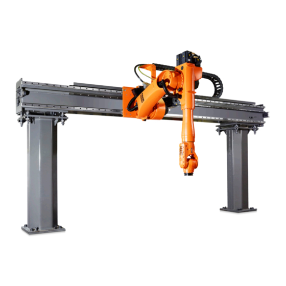
Axis module JET ROBOT Robot controller Connecting cables Teach pendant KCP (KUKA smartPAD) Software Options, accessories Fig. 3-1: KR 60 L30-2 JET robot system (example) KR 60 L30-2 JET KR C4 robot controller... - Page 10 KR 30-2 JET; KR 60-2 JET Fig. 3-2: Principal components Beam Carriage Energy supply chain Column The axis module can be assembled from the following column variants: Columns End column, bottom End column, side Intermediate column, rear-mounted, bottom ...
- Page 11 3 Product description Electrical installations Fig. 3-3: Main assemblies of the KR 30, 60 JET ROBOT In-line wrist Rotating column Link arm Electrical installations The robot (>>> Fig. 3-3 ) is fitted with a 3-axis in-line wrist (1). The in-line wrist In-line wrist contains axes 4, 5 and 6.
- Page 12 KR 30-2 JET; KR 60-2 JET Issued: 08.09.2015 Version: Spez KR 30, 60-2 JET V1 12 / 85...
-
Page 13: Technical Data
4 Technical data Technical data Basic data Basic data Type KR 30-2 JET ROBOT Number of axes Robot 5, JET ROBOT Linear axis 1 Workspace 5.7 m Repeatability ±0.07 mm (ISO 9283) Working envelope ref- Intersection of axes 4 and 5... -
Page 14: Basic Data
KR 30-2 JET; KR 60-2 JET For operation with KR C4, a ground conductor is always required, which can be ordered separately as an option. The cable length between the robot controller and the robot junction box must not exceed 50 m. The cable lengths in the energy supply chain must therefore also be taken into account. -
Page 15: Basic Data
Sound level < 75 dB (A) outside the working envelope Mounting position inverted, side-mounted Surface finish, paint- Moving parts: KUKA orange 2567 work Ambient temper- Operation 283 K to 328 K (+100 °C to +55 °C) ature Storage and transpor- 233 K to 333 K (-40 °C to +60 °C) -
Page 16: Basic Data
KR 30-2 JET; KR 60-2 JET Cable designation Connector designa- Interface with robot tion Data cable X21 - X31 Harting connectors at both ends Ground conductor Ring cable lug, both sides, Cable lengths Standard 7 m, 15 m, 25 m, 35 m... -
Page 17: Axis Data
4 Technical data Start-up In the case of start-up in the range of 278 K to 288 K (+5 °C to +15 °C), the robot may have to be warmed up. Other temperature limits available on request. Ambient conditions DIN EN 60721-3-3, Class 3K3 Connecting Cable designation... - Page 18 Working tion of axes 4 and 5. envelope Fig. 4-2: Working envelope for KR 30-2 JET The reference plane for the working envelope of the robot is axis 2. With side Reference plane mounting, it is offset 155 mm below the center of the beam. With inverted mounting, the offset is 155 mm to the rear.
-
Page 19: Axis Data
4 Technical data refer to the floor and to the center of the carriage in the case of side mounting, and to the bolt-on surface of the carriage in the case of inverted mounting. Fig. 4-3: Reference plane Bolt-on surface Center of beam Rotational axis A2 Column height... - Page 20 KR 30-2 JET; KR 60-2 JET Fig. 4-4: Direction of rotation of robot axes The diagram (>>> Fig. 4-8 ) shows the shape and size of the working enve- lope. The reference point for the working envelope (>>> Fig. 4-5 ) is the intersec- Working tion of axes 4 and 5.
-
Page 21: Axis Data
4 Technical data refer to the floor and to the center of the carriage in the case of side mounting, and to the bolt-on surface of the carriage in the case of inverted mounting. Fig. 4-6: Reference plane Bolt-on surface Center of beam Rotational axis A2 Column height... - Page 22 KR 30-2 JET; KR 60-2 JET Fig. 4-7: Direction of rotation of robot axes The diagram (>>> Fig. 4-8 ) shows the shape and size of the working enve- lope. The reference point for the working envelope is the intersection of axes 4 and...
-
Page 23: Axis Data
4 Technical data refer to the floor and to the center of the carriage in the case of side mounting, and to the bolt-on surface of the carriage in the case of inverted mounting. Fig. 4-9: Reference plane Bolt-on surface Center of beam Rotational axis A2 Column height... - Page 24 KR 30-2 JET; KR 60-2 JET Fig. 4-10: Direction of rotation of robot axes The diagram (>>> Fig. 4-8 ) shows the shape and size of the working enve- lope. The reference point for the working envelope (>>> Fig. 4-11 ) is the intersec- Working tion of axes 4 and 5.
-
Page 25: Order-Specific Technical Data
4 Technical data refer to the floor and to the center of the carriage in the case of side mounting, and to the bolt-on surface of the carriage in the case of inverted mounting. Fig. 4-12: Reference plane Bolt-on surface Center of beam Rotational axis A2 Column height... -
Page 26: Payloads
KR 30-2 JET; KR 60-2 JET Principal dimen- sions Fig. 4-13: Principal dimensions (example) 4.10 Payloads Payloads Robot KR 30 JET ROBOT In-line wrist IW 30, 45, 60 Rated payload 30 kg Distance of the load center of gravity L... - Page 27 For commissioning the robot, additional input data are required in accor- dance with the operating and programming instructions of the KUKA System Software. The mass inertia must be verified using KUKA.Load. It is imperative for the load data to be entered in the robot controller! Mounting flange...
- Page 28 KR 30-2 JET; KR 60-2 JET The mounting flange is depicted (>>> Fig. 4-15 ) with axes 4 and 6 in the zero position. The symbol X indicates the position of the locating element (bush- ing) in the zero position.
-
Page 29: Payloads
4 Technical data Fig. 4-16: Supplementary load on arm Center of mounts for supple- M8 hole, 16 deep mentary load Axis 3 Interference contour for sup- plementary load Mounting surface for sup- plementary load 4.11 Payloads Payloads Robot KR 60 JET ROBOT In-line wrist IW 30, 45, 60 Rated payload... - Page 30 For commissioning the robot, additional input data are required in accor- dance with the operating and programming instructions of the KUKA System Software. The mass inertia must be verified using KUKA.Load. It is imperative for the load data to be entered in the robot controller! Mounting flange...
- Page 31 4 Technical data Fig. 4-18: Mounting flange M8 fastening screws, grade 10.9 Depth of engagement: min. 12 mm max. 14 mm Ø63 usable fit depth 6 mm The robot can carry supplementary loads on the arm. When mounting the sup- Supplementary plementary loads, be careful to observe the maximum permissible total load.
-
Page 32: Payloads
KR 30-2 JET; KR 60-2 JET Fig. 4-19: Supplementary load on arm Center of mounts for supple- M8 hole, 16 deep mentary load Axis 3 Interference contour for sup- plementary load Mounting surface for sup- plementary load 4.12 Payloads Payloads... - Page 33 For commissioning the robot, additional input data are required in accor- dance with the operating and programming instructions of the KUKA System Software. The mass inertia must be verified using KUKA.Load. It is imperative for the load data to be entered in the robot controller! Mounting flange...
- Page 34 KR 30-2 JET; KR 60-2 JET Fig. 4-21: Mounting flange M8 fastening screws, grade 10.9 Depth of engagement: min. 12 mm max. 14 mm Ø63 usable fit depth 6 mm The robot can carry supplementary loads on the arm. When mounting the sup- Supplementary plementary loads, be careful to observe the maximum permissible total load.
-
Page 35: Payloads
4 Technical data Fig. 4-22: Supplementary load on arm Center of mounts for supple- M8 hole, 16 deep mentary load Axis 3 Interference contour for sup- plementary load Mounting surface for sup- plementary load 4.13 Payloads Payloads Robot KR 60 L45 JET ROBOT In-line wrist IW 30, 45, 60 Rated payload... - Page 36 For commissioning the robot, additional input data are required in accor- dance with the operating and programming instructions of the KUKA System Software. The mass inertia must be verified using KUKA.Load. It is imperative for the load data to be entered in the robot controller! Mounting flange...
- Page 37 4 Technical data Fig. 4-24: Mounting flange M8 fastening screws, grade 10.9 Depth of engagement: min. 12 mm max. 14 mm Ø63 usable fit depth 6 mm The robot can carry supplementary loads on the arm. When mounting the sup- Supplementary plementary loads, be careful to observe the maximum permissible total load.
-
Page 38: Foundation Loads
KR 30-2 JET; KR 60-2 JET Fig. 4-25: Supplementary load on arm Center of mounts for supple- M8 hole, 16 deep mentary load Axis 3 Interference contour for sup- plementary load Mounting surface for sup- plementary load 4.14 Foundation loads... - Page 39 4 Technical data The mounting base loads specified in the table are the maximum loads that may occur. They must be referred to when dimensioning the mounting bases and must be adhered to for safety reasons. The supplementary loads on the rotating column are not taken into consider- ation in the calculation of the foundation load.
-
Page 40: Plates And Labels
KR 30-2 JET; KR 60-2 JET L2 - L5 2 columns 6.5 m 3 - 2 columns 6.5 m 6.5 m Column spacing with two carriages L2 - L6 2 columns 6.5 m 3 - 7 columns 6.5 m 6.5 m... -
Page 41: Stopping Distances And Times
4 Technical data Fig. 4-27: Plates and labels 4.16 Stopping distances and times 4.16.1 General information Information concerning the data: The stopping distance is the angle traveled by the robot from the moment the stop signal is triggered until the robot comes to a complete standstill. The stopping time is the time that elapses from the moment the stop signal ... -
Page 42: Terms Used
KR 30-2 JET; KR 60-2 JET The data are given for the main axes A1, A2 and A3. The main axes are the axes with the greatest deflection. Superposed axis motions can result in longer stopping distances. Stopping distances and stopping times in accordance with DIN EN ISO ... -
Page 43: Stopping Distances And Stopping Times For Stop 0, Axis 1 To Axis 3
4 Technical data Fig. 4-28: Extension 4.16.3 Stopping distances and stopping times for STOP 0, axis 1 to axis 3 The table shows the stopping distances and stopping times after a STOP 0 (category 0 stop) is triggered. The values refer to the following configuration: Extension l = 100% ... -
Page 44: Stopping Distances And Stopping Times For Stop 1, Axis 1
KR 30-2 JET; KR 60-2 JET 4.16.4 Stopping distances and stopping times for STOP 1, axis 1 Fig. 4-29: Stopping distances for STOP 1, axis 1 Issued: 08.09.2015 Version: Spez KR 30, 60-2 JET V1 44 / 85... - Page 45 4 Technical data Fig. 4-30: Stopping times for STOP 1, axis 1 Issued: 08.09.2015 Version: Spez KR 30, 60-2 JET V1 45 / 85...
-
Page 46: Stopping Distances And Stopping Times For Stop 1, Axis 2
KR 30-2 JET; KR 60-2 JET 4.16.5 Stopping distances and stopping times for STOP 1, axis 2 Fig. 4-31: Stopping distances for STOP 1, axis 2 Issued: 08.09.2015 Version: Spez KR 30, 60-2 JET V1 46 / 85... - Page 47 4 Technical data Fig. 4-32: Stopping times for STOP 1, axis 2 Issued: 08.09.2015 Version: Spez KR 30, 60-2 JET V1 47 / 85...
-
Page 48: Stopping Distances And Stopping Times For Stop 1, Axis 3
KR 30-2 JET; KR 60-2 JET 4.16.6 Stopping distances and stopping times for STOP 1, axis 3 Fig. 4-33: Stopping distances for STOP 1, axis 3 Fig. 4-34: Stopping times for STOP 1, axis 3 Issued: 08.09.2015 Version: Spez KR 30, 60-2 JET V1... -
Page 49: Safety
No modifications may be carried out to the industrial robot without the autho- rization of KUKA Roboter GmbH. Additional components (tools, software, etc.), not supplied by KUKA Roboter GmbH, may be integrated into the indus- trial robot. The user is liable for any damage these components may cause to the industrial robot or to other material property. -
Page 50: Intended Use Of The Industrial Robot
KR 30-2 JET; KR 60-2 JET 5.1.2 Intended use of the industrial robot The industrial robot is intended exclusively for the use designated in the “Pur- pose” chapter of the operating instructions or assembly instructions. Any use or application deviating from the intended use is deemed to be misuse and is not allowed. -
Page 51: Terms Used
External axis Motion axis which is not part of the manipulator but which is controlled using the robot controller, e.g. KUKA linear unit, turn-tilt table, Posiflex. Personnel The following persons or groups of persons are defined for the industrial robot: User ... -
Page 52: Workspace, Safety Zone And Danger Zone
KR 30-2 JET; KR 60-2 JET Personnel All persons working with the industrial robot must have read and un- derstood the industrial robot documentation, including the safety chapter. The user must observe the labor laws and regulations. This includes e.g.: User The user must comply with his monitoring obligations. -
Page 53: Overview Of Protective Equipment
The manipulator must be taken out of operation and KUKA Roboter GmbH must be consulted before it is put back into operation (>>>... -
Page 54: Options For Moving The Manipulator Without Drive Energy
Information about the options available for the various robot models and about how to use them can be found in the assembly and oper- ating instructions for the robot or requested from KUKA Roboter GmbH. Moving the manipulator without drive energy can dam- age the motor brakes of the axes concerned. -
Page 55: Safety Measures
5 Safety Safety measures 5.5.1 General safety measures The industrial robot may only be used in perfect technical condition in accor- dance with its intended use and only by safety-conscious persons. Operator errors can result in personal injury and damage to property. It is important to be prepared for possible movements of the industrial robot even after the robot controller has been switched off and locked out. -
Page 56: Transportation
Avoid vibrations and impacts during transportation in order to prevent damage to the robot controller. The prescribed transport position of the external axis (e.g. KUKA linear unit, External axis turn-tilt table, positioner) must be observed. Transportation must be carried... - Page 57 If additional components (e.g. cables), which are not part of the scope of supply of KUKA Roboter GmbH, are integrated into the industrial robot, the user is responsible for ensuring that these components do not adversely affect or disable safety functions.
-
Page 58: Manual Mode
KR 30-2 JET; KR 60-2 JET 5.5.4 Manual mode Manual mode is the mode for setup work. Setup work is all the tasks that have to be carried out on the industrial robot to enable automatic operation. Setup work includes: Jog mode ... -
Page 59: Maintenance And Repair
Death or severe injuries may result. Faulty components must be replaced using new components with the same article numbers or equivalent components approved by KUKA Roboter GmbH for this purpose. Cleaning and preventive maintenance work is to be carried out in accordance with the operating instructions. -
Page 60: Decommissioning, Storage And Disposal
KR 30-2 JET; KR 60-2 JET Some robot variants are equipped with a hydropneumatic, spring or gas cylin- Counterbal- der counterbalancing system. ancing system The hydropneumatic and gas cylinder counterbalancing systems are pressure equipment and, as such, are subject to obligatory equipment monitoring and the provisions of the Pressure Equipment Directive. - Page 61 5 Safety 1997 97/23/EC Pressure Equipment Directive: Directive 97/23/EC of the European Parliament and of the Council of 29 May 1997 on the approximation of the laws of the Member States concerning pressure equipment (Only applicable for robots with hydropneumatic counterbal- ancing system.) 2008 EN ISO 13850...
- Page 62 KR 30-2 JET; KR 60-2 JET Issued: 08.09.2015 Version: Spez KR 30, 60-2 JET V1 62 / 85...
-
Page 63: Planning
If one or more of these conditions are to apply during operation of the kinemat- ic system, KUKA Roboter GmbH must be consulted. If the robot reaches its corresponding operation limit or if it is operated near the limit for a period of time, the built-in monitoring functions come into effect and the robot is automatically switched off. - Page 64 KR 30-2 JET; KR 60-2 JET Fig. 6-1: Mounting base, installation Column, base plate Bedplate Fastening elements Resin-bonded anchor Weld-on plate Leveling screw The following illustration (>>> Fig. 6-2 ) provides all the necessary information Dimensioned on the mounting base with bedplate, together with the required foundation da- drawing ta.
-
Page 65: Connecting Cables And Interfaces
6 Planning foundation. The quality of the concrete must meet the requirements of the fol- lowing standard: C20/25 according to DIN EN 206-1:2001/DIN 1045-2:2008 Connecting cables and interfaces The connecting cables comprise all the cables for transferring energy and sig- Description nals between the robot controller and the robot. - Page 66 KR 30-2 JET; KR 60-2 JET Issued: 08.09.2015 Version: Spez KR 30, 60-2 JET V1 66 / 85...
-
Page 67: Transportation
7 Transportation Transportation Transportation Move the robot into its transport position each time it is transported. It must be ensured that the robot is stable while it is being transported. The robot must remain in its transport position until it has been fastened in position. Before the robot is lifted, it must be ensured that it is free from obstructions. - Page 68 KR 30-2 JET; KR 60-2 JET Fig. 7-2: Transport dimensions Robot Fork slots Center of gravity The fork slots must be installed for transport. The robot can be transported by fork lift truck or using lifting tackle. The fork Transportation slots must be properly and fully installed.
- Page 69 7 Transportation The robot (>>> Fig. 7-4 ) can be transported using lifting tackle. The robot Transportation must be in the transport position. The lifting tackle is attached with hooks to using lifting the fork slots screwed to the rotating column. All ropes must be long enough tackle and must be routed in such a way that the robot is not damaged.
- Page 70 KR 30-2 JET; KR 60-2 JET Fig. 7-5: Transport frame Transport frame for inverted robot Transport frame for side-mounted robot Center of gravity The beam (>>> Fig. 7-6 ) can be transported with a fork lift truck or using lift- Transporting the ing tackle and a crane.
- Page 71 7 Transportation Lifting tackle Transport aid, load stands, M20 Beam Issued: 08.09.2015 Version: Spez KR 30, 60-2 JET V1 71 / 85...
- Page 72 KR 30-2 JET; KR 60-2 JET Issued: 08.09.2015 Version: Spez KR 30, 60-2 JET V1 72 / 85...
-
Page 73: Options
8 Options Options Release device (optional) The release device can be used to move the manipulator manually after an ac- Description cident or malfunction. The release device can be used for the motors of axes 1 to 5. It cannot be used for axis 6, as this motor is not accessible. It is only for use in exceptional circumstances and emergencies (e.g. - Page 74 KR 30-2 JET; KR 60-2 JET Issued: 08.09.2015 Version: Spez KR 30, 60-2 JET V1 74 / 85...
-
Page 75: Kuka Service
tions Diagnostic package KrcDiag: Additionally for KUKA Sunrise: Existing projects including applications For versions of KUKA System Software older than V8: Archive of the software (KrcDiag is not yet available here.) Application used External axes used ... - Page 76 KR 30-2 JET; KR 60-2 JET KUKA Automatisering + Robots N.V. Belgium Centrum Zuid 1031 3530 Houthalen Belgium Tel. +32 11 516160 Fax +32 11 526794 info@kuka.be www.kuka.be KUKA Roboter do Brasil Ltda. Brazil Travessa Claudio Armando, nº 171 Bloco 5 - Galpões 51/52 Bairro Assunção...
- Page 77 9 KUKA Service KUKA Automatisme + Robotique SAS France Techvallée 6, Avenue du Parc 91140 Villebon S/Yvette France Tel. +33 1 6931660-0 Fax +33 1 6931660-1 commercial@kuka.fr www.kuka.fr KUKA Robotics India Pvt. Ltd. India Office Number-7, German Centre, Level 12, Building No. - 9B...
- Page 78 Taman Perindustrian Puchong 47100 Puchong Selangor Malaysia Tel. +60 (03) 8063-1792 Fax +60 (03) 8060-7386 info@kuka.com.my KUKA de México S. de R.L. de C.V. Mexico Progreso #8 Col. Centro Industrial Puente de Vigas Tlalnepantla de Baz 54020 Estado de México Mexico Tel.
- Page 79 Werbnaja ul. 8A 107143 Moskau Russia Tel. +7 495 781-31-20 Fax +7 495 781-31-19 info@kuka-robotics.ru www.kuka-robotics.ru KUKA Svetsanläggningar + Robotar AB Sweden A. Odhners gata 15 421 30 Västra Frölunda Sweden Tel. +46 31 7266-200 Fax +46 31 7266-201 info@kuka.se...
- Page 80 KR 30-2 JET; KR 60-2 JET KUKA Robots IBÉRICA, S.A. Spain Pol. Industrial Torrent de la Pastera Carrer del Bages s/n 08800 Vilanova i la Geltrú (Barcelona) Spain Tel. +34 93 8142-353 Fax +34 93 8142-950 comercial@kukarob.es www.kuka.es Jendamark Automation LTD (Agency)
- Page 81 9 KUKA Service KUKA Robotics Hungaria Kft. Hungary Fö út 140 2335 Taksony Hungary Tel. +36 24 501609 Fax +36 24 477031 info@kuka-robotics.hu KUKA Robotics Corporation 51870 Shelby Parkway Shelby Township 48315-1787 Michigan Tel. +1 866 873-5852 Fax +1 866 329-5852 info@kukarobotics.com...
- Page 82 KR 30-2 JET; KR 60-2 JET Issued: 08.09.2015 Version: Spez KR 30, 60-2 JET V1 82 / 85...
-
Page 83: Index
ISO 9283, repeatability 13, 14, 15, 16 Carriage 10 CE mark 50 KCP 51, 55 Center of gravity 67 KCP, KUKA Control Panel 42 Cleaning work 59 Keyboard, external 55 Columns 10 KUKA Customer Support 75 Connecting cables 9, 13, 14, 15, 17, 49, 65... - Page 84 KR 30-2 JET; KR 60-2 JET Mechanical axis range limitation 53 STOP 2 51 Mechanical end stops 53 Stop category 0 51 Mounting base 63 Stop category 1 51 Mounting flange 11, 27, 30, 33, 36 Stop category 2 51...
- Page 85 KR 30-2 JET; KR 60-2 JET Issued: 08.09.2015 Version: Spez KR 30, 60-2 JET V1 85 / 85...
Need help?
Do you have a question about the KR 30-2 and is the answer not in the manual?
Questions and answers