Table of Contents
Advertisement
CONTENTS
Mounting to the wall
Relays
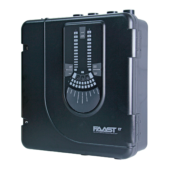
INTRODUCTION
The LT-200 FL01 Series is part of the Fire Alarm Aspiration Sensing
Technology
(FAAST) family. FAAST is an advanced fire detection
®
system for use where early warning and very early warning are a
requirement. The system continuously draws air from the controlled
environment through a series of sampling holes to monitor the
environment for smoke particulate.
The FL01 is the stand-alone version of the FAAST LT-200 range and is
available in 3 different models:
FL0111E-HS - Has single channel capability with one high sensitivity
smoke sensor.
FL0112E-HS - Has single channel capability with two high sensitivity
smoke sensors in a common chamber for coincidence detection.
FL0122E-HS - Has two channel capability with two high sensitivity
smoke sensors in separate chambers. (One sensor for each channel).
This guide provides information for mounting the unit, basic installation
and advice on pipe layout designs, together with an overview of
using the PipeIQ™ software (version 2.9.1 or higher) to achieve
EN54 compliant designs. For more complex designs using increased
functionality (experienced users only) please see the FAAST LT-200
Advanced Setup and Control Guide - reference D200-100-01.
Important Note
Aspirating Smoke Detectors supplied and installed within the EU must
conform to the EU Construction Products Regulation (CPR) 305/2011
and the related European Product Standard EN 54-20. FAAST LT-200
has been tested and certified to ensure that it conforms to the necessary
Standards, but strict adherence to this instruction guide is advised to
ensure that the installation meets the requirements of the CPR.
The PipeIQ™ software (use version 2.9.1 or higher) is a design
application to help a user create or verify EN54 compliant pipe layouts,
and to allow configuration of the FAAST LT-200 unit.
The performance of this system is dependent upon the pipe
network. Any extension or modification to the designed installation
may cause improper operation. The operational effects of such
changes need to be verified using the PipeIQ design software.
This equipment and all associated pipe work must be installed in
accordance with all relevant codes and regulations.
D200-101-01
Fire Alarm Aspiration Sensing Technology
FL0111E-HS FL0112E-HS FL0122E-HS
STAND-ALONE FAAST LT-200 MODELS
1
Front Panel
1
Buttons
1
Testing
2
Service
2
PipeIQ™ Software
2
3
Appendix A -
4
4
Appendix B -
5
Practical Pipe Designs
5
6
Warning
QUICK INSTALLATION GUIDE
6
7
8
8
9
11
PARTS LIST
Description
SPECIFICATIONS
Electrical Characteristics
Voltage Range:
Supply Current: 1 Channel: 170mA (typical); 360mA (max) @ 24
Configurable Input:
Relay Contact Ratings:
Environmental Ratings
Temperature:
Relative Humidity:
Flow Fault:
IP Rating:
Mechanical
Wiring:
Maximum Single Pipe Length: 100m (Class C)
Maximum Branched Pipe Length: 160m (2 x 80m, Class C)
Maximum Number of Holes: See Table 1A
Pipe Spec (EN54-20 Compliance): to EN 61386
Outside Pipe Diameter:
Shipping Weight:
1
®
Quantity
1
1
6
1
3
2
1
1
1
1
1
18.5 - 31.5 VDC
VDC 25
C (excluding sounders)
o
2 Channel: 270mA (typical); 570mA (max) @ 24
VDC 25
C (excluding sounders)
o
Activation Time: 2s (min)
2.0 A @ 30 VDC, 0.5A @ 30 VAC
-10°C to 55°C
10% to 93% (non-condensing)
± 20% of the reference flow
65
0.5 mm² to 2 mm² max
(Crush 1, Impact 1, Temp 31)
25mm (nom) or 27mm (nom)
6.5kg (inc sensors)
ENGLISH
I 56- 6574- 000
I56-6574-000
Advertisement
Table of Contents

Related Manuals for System Sensor FAAST FL0111E-HS


Summary of Contents for System Sensor FAAST FL0111E-HS
-
Page 1: Table Of Contents
ENGLISH Fire Alarm Aspiration Sensing Technology ® FL0111E-HS FL0112E-HS FL0122E-HS STAND-ALONE FAAST LT-200 MODELS I 56- 6574- 000 QUICK INSTALLATION GUIDE CONTENTS Introduction Front Panel Parts List Indicators and fault descriptions 7 Buttons Specifications Testing Physical Installation Service Front panel labels PipeIQ™... -
Page 2: Front Panel Labels
50 mm 50 mm 60 mm 65 mm 26 mm Cable Access Knock out cable gland holes where required. The location of the cable gland holes is shown in Figure 1, represented by the icon: Figure 4: How to Knock Out Cable Gland Holes Mounting the LT-200 FL01 to the Wall INDICATES CENTRE OF ASPIRATING PIPES... -
Page 3: 2-Pin Terminal Block
Pipe Hole Configuration Figure 7: Sequence (1 to 9) to Mount the Detector on the Bracket Figure 8 below shows the pipe holes available on the unit. Each unit has 2 pipe holes per channel connected together like a T-Piece. If 99 mm using a 1 channel unit, holes 3 and 4 do not function. -
Page 4: Wiring Installation
Exhaust Pipe Whenever the FAAST LT-200 is installed outside the risk area, return of the exhaust air back into the protected area can reduce flow faults due to pressure difference. SAMPLING AREA IMPORTANT NOTES 1) Do not glue the pipes into the inlets or outlets of the FAAST LT- 200 unit. -
Page 5: Terminal Designations
Fitting the Terminal Blocks WARNING: Switching Inductive Loads To insert the terminal blocks into the unit use the following method: FAAST LT Insert a corner of the block into the slot (see a). Push the length of the block into the slot until the block ‘clicks’ into place, the 2 upper hooks on the block should be visible (see c). -
Page 6: External Reset
POWERING UP Using Default Settings 1. Connect a suitable 24VDC supply (complying with European Standard EN 54-4) to pins 1 and 2 on terminal block T1 (See ALARM Table 2) PREALARM 2. Check the voltage at the connector. Make sure it is within the required voltage range. -
Page 7: Indicators And Fault Descriptions
Table 4: Front Panel Indicators and Fault Descriptions INDICATOR ACTION WARNING OR TROUBLE COMMENT / ACTION CHANNEL 1/2 ON Red Channel is in alarm (relay is set) No delay with default settings ALARM 1 BLINK Green when sensor is polled Not in alarm CHANNEL 1/2 PRE- ON Yellow... - Page 8 ALARM PREALARM ALARM PREALARM SMOKE Password Sequence to Enter Maintenance Mode Filters LEVEL 2 Periodic cleaning or replacement of the filters will be required. INITIALIZATION 1) Press and hold RESET; Left flow indicator will turn The filters are located inside the cabinet at the top of the unit (see POWER yellow, then green.
-
Page 9: Introduction
1) With PipeIQ open on the PC and the device in Maintenance mode, open the device front door by releasing the two Phillips screws. System Sensor Europe Life Safety Distribution GmbH 2) Connect a USB cable from the internal port in the centre of the... -
Page 10: Appendix A - Pipeiq™ And Pipe System Design
APPENDIX A - PipeIQ™ and PIPE SYSTEM DESIGN USING PipeIQ™ for SYSTEM DESIGN Pipe Design Methodology Flow Chart PIPE DESIGN METHODOLOGY FLOW CHART PipeIQ is a design application to help a user create EN54 compliant Start Project pipe layouts. Generating a suitable working design will require some and create thought and understanding of the interacting variables in an aspirating pipe layout... - Page 11 APPENDIX B - PRACTICAL PIPE DESIGNS for ASPIRATING SYSTEMS The following tables show some typical EN54 CLASS C PIPE DESIGNS WITH SINGLE SAMPLE HOLE/END HOLE SIZE AND 10m SPACING compliant pipe designs for FAAST LT-200 1 PIPE devices with different overall pipe lengths. Pipe Number Hole End Air Flow Average Alarm Fan Total hole Each design has a one size sample hole for Length ...
- Page 12 CLASS C PIPE DESIGNS WITH SINGLE SAMPLE HOLE SIZE (Inc. SAMPLING END HOLE) AND 10m SPACING ‐ 2 PIPE (T‐FORM) Pipe Number Hole Air Flow Average Alarm Fan Total Length of holes size flow balance sensitivity level hole area (m) (mm) (I/min) (%/m) ) 80 X ‐ ‐ ‐ ‐ ‐ ‐ ‐ 70 X ‐ ‐ ...
- Page 13 CLASS A PIPE DESIGNS WITH SINGLE SAMPLE HOLE SIZE (Inc. SAMPLING END HOLE) AND 10m SPACING 1 PIPE Pipe Number Hole End Air Flow Average Alarm Fan Total hole Length of holes size hole flow balance sensitivity level area (m) (mm) (mm) (I/min) (%/m) ) 80 X ‐ ‐ ‐ ‐ ‐ ‐ ‐ ‐ ...
Need help?
Do you have a question about the FAAST FL0111E-HS and is the answer not in the manual?
Questions and answers