Advertisement
Quick Links
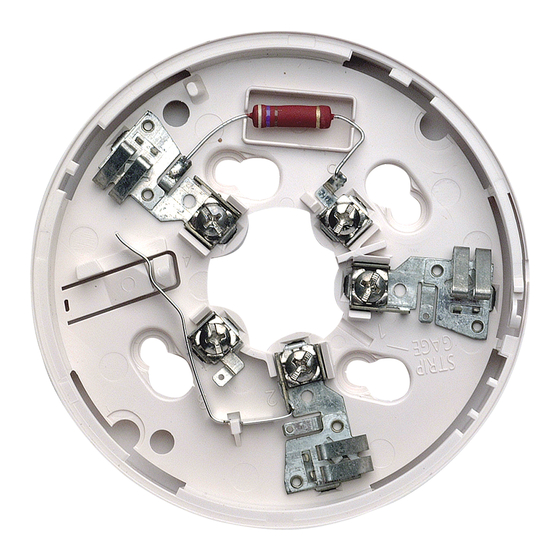
INSTALLATION AND MAINTENANCE INSTRUCTIONS
B401 Plug-In Detector Base
For use with the following detectors:
US Models:
1151, 1451, 2151, 2451, 2451TH, 5451
European Models:
1151E, 1451E, 2151E, 2451E, 5451E
Australian Models:
1151AUS, 1451AUS, 2151AUS, 2451AUS, 4451AUS
5451AUS, 51A51, 51B51, 51C51, 51D51
Specifications
Base Diameter:
Base Height:
Weight:
Mounting:
Operating Temperature Range:
Operating Humidity Range:
Electrical Ratings — includes base and detector
System Voltage:
Maximum Ripple Voltage:
Start-up Capacitance:
Standby Ratings:*
Alarm Ratings:
Reset Voltage:
Reset Time:
Start-up Time:
* 1151E: 30 µA Maximum.
** Alarm current MUST be limited to 100 mA maximum (130 mA for models 1151 and 2151) by the control panel.
If used, the RA400Z Remote Annunciator operates within the specified detector alarm currents.
Before Installing
Please thoroughly read the System Smoke Detectors
Application Guide, which provides detailed information
on detector spacing, placement, zoning, wiring, and spe-
cial applications. Copies of this manual are available from
System Sensor.
NOTICE: This manual should be left with the owner/user
of this equipment.
IMPORTANT: The detector used with this base must be
tested and maintained regularly following NFPA 72 require-
ments. The detector used with this base should be cleaned
at least once a year.
10.2 cm (4.0 inches)
2.0 cm (0.8 inches)
152 g (0.34 lb.)
50 mm box
60 mm box
–10° to +60°C (14° to 140°F) — European Installation
0° to 49°C (32° to 120°F) — US/Australian Installation
10% to 93% Relative Humidity
Base And Smoke Detector
12/24 VDC
4 Volts peak to peak
0.02 µF Maximum
8.5 VDC Minimum
35 VDC Maximum
120 µA Maximum
4.2 VDC Minimum at 10 mA**
6.6 VDC Maximum at 100 mA**
2.5 VDC Minimum
0.3 Seconds Maximum
34 Seconds Maximum
1
3825 Ohio Avenue, St. Charles, Illinois 60174
Base And Heat Detector
24 VDC
4 Volts peak to peak
0.02 µF Maximum
15 VDC Minimum
35 VDC Maximum
100 µA Maximum
4.2 VDC Minimum at 10 mA**
6.6 VDC Maximum at 100 mA**
2.5 VDC Minimum
0.3 Seconds Maximum
34 Seconds Maximum
General Description
This B401 plug-in detector base is used with System Sensor
smoke and heat detector heads. The capability of plugging
these detectors into a variety of special bases makes them
more versatile than equivalent direct-wired models. Refer
to the System Sensor catalog for other available plug-in
detector bases.
The B401 base is intended for use in 2-wire systems, with
screw terminals provided for power and remote annuncia-
tor connections.
1-800-SENSOR2, FAX: 630-377-6495
www.systemsensor.com
I56-0338-010R
03-11
Advertisement

Related Manuals for System Sensor B401


Summary of Contents for System Sensor B401
- Page 1 NOTICE: This manual should be left with the owner/user of this equipment. The B401 base is intended for use in 2-wire systems, with screw terminals provided for power and remote annuncia- IMPORTANT: The detector used with this base must be tor connections.
- Page 2 System Sensor maintains a list of two-wire detectors and control panels that are listed as compatible. The 2-Wire Compatibility Chart is available from System Sensor at no charge.
- Page 3 Figure 2. Typical 2-wire detector wiring configuration: REMOTE REMOTE ANNUNCIATOR ANNUNCIATOR CLASS A OPTIONAL WIRING C0529-00 erly wired and mounted to an electrical box, make sure tant tab before installing the detector (see Figure 3A). The that the shorting spring is in contact with terminal 3. This tamper-resistant tab is on the detector mounting base.
- Page 4 Please refer to insert for the Limitations of Fire Alarm Systems Three-Year Limited Warranty System Sensor warrants its enclosed smoke detector base to be free from Honeywell, 12220 Rojas Drive, Suite 700, El Paso TX 79936 USA. Please defects in materials and workmanship under normal use and service for a include a note describing the malfunction and suspected cause of failure.
Need help?
Do you have a question about the B401 and is the answer not in the manual?
Questions and answers