Advertisement
Quick Links
INSTALLATION AND MAINTENANCE INSTRUCTIONS
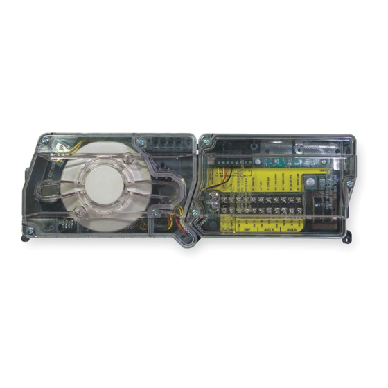
D4120A Duct Smoke Detector
D4SA Sensor Component
D4P120A Power Board Component
NOTE: The D4120A duct detector consists of D4P120A Power Board component and the D4SA Sensor component.
SPECIFICATIONS
Operating Temperature:
Storage Temperature:
Humidity:
Air Velocity:
D4120A Footprint Dimensions:
D4SA/D4P120A Footprint Dimensions: 7.75 in L x 5 in W x 2.5 in D (19.7cm L x 12.7cm W x 6.35cm D)
D4120A Weight:
Electrical
Power supply voltage:
Input capacitance:
Reset Voltage:
Reset Time (with RTS451):
Reset Time (by power down):
Power Up Time:
Alarm response time:
Sensitivity Test:
Current Requirements (Using No Accessories)
Standby current
Alarm current
CONTACT RATINGS
Alarm initiation contacts
(SPST)
Alarm auxiliary contatcs
(DPDT)
NOTE: Alarm auxiliary contacts shall not be connected to initiating
circuits of control panels. Use the alarm initiation contact for this
purpose.
Supervisory Contacts
(SPDT)
TABLE OF CONTENTS
[1] Limitations of Duct Smoke Detectors
[2] Exploded View of Duct Smoke Detector Components
[3] General Description
[4] Contents of Duct Smoke Detector Kit
[5] Detector Installation
[6] Sampling Tube Installation
[7] Measurement Tests
[8] Field Wiring Installation Guidelines
[9] Unit Configuration
[10] Detector Status Indication
[11] Interconnection (Multiple Fan Shut Down)
[12] Verification of Operation
[13] Detector Cleaning Procedures
[14] Sensor replacement
[15] Optional Accessories
Wiring Diagrams
Warranty
BEFORE INSTALLING
Read the System Sensor Guide for Proper Use of Smoke Detectors in Duct
Applications (HVAG53), which provides information on detector spacing,
placement, zoning, wiring, and special applications. This manual is available
online at www.systemsensor.ca. CAN/ULC S524 should also be referenced
for detailed information.
NOTICE: This manual shall be left with the owner/user of this equipment.
D4120A & D4SA: –4° to 158° F (–20° to 70° C) D4P120A: –40° to 158° F (–40° to 70° C)
D4120A & D4SA: –22° to 158° F (–30° to 70° C) D4P120A: –40° to 158° F (–40° to 70° C)
0% to 95% Relative Humidity Non-condensing
100 to 4000 ft./min. (0.5 to 20.3 m/sec.)
Rectangular - 14.38 in L x 5 in W x 2.5 in D (37cm L x 12.7cm W x 6.36cm D)
Square - 7.75 in L x 9 in W x 2.5 in D (19.7cm L x 22.9cm W x 6.35cm D)
2.5 pounds; 1.14 kg
20-29 VDC
270 µF max.
3.0 VDC min.
.03 to 0.3 sec.
0.6 sec. max.
35 sec. max.
15 sec.
See detector label
21 mA @ 24 VDC
65 mA @ 24 VDC
2.0A @ 30 VDC (resistive)
10A @30 VDC (resistive)
10A @250 VAC (resistive)
1
/
HP @240 VAC
2
1
/
HP @120 VAC
4
2.0A @ 30 VDC (resistive)
2.0A @ 125 VAC (resistive)
24 VAC 50-60-Hz
270 µF max.
2.0 VAC min.
.03 to 0.3 sec.
0.6 sec. max.
35 sec. max.
15 sec.
See detector label
65 mA RMS @ 24VAC 60Hz
135 mA RMS @ 24 VAC 60 Hz
ACCESSORY CURRENT LOADS AT 24 VDC
DEVICE
MHRA/MHWA
RA400ZA
RTS451
RTS451KEYA
NOTE: Any combination of accessories may be used such that the given
accessory loads are: 110mA or less at the Aux output, and 50mA or less at
the Alarm output.
PAGE
IMPORTANT: This detector must be tested and maintained regularly follow-
1
ing CAN/ULC S536 requirements. The detector should be cleaned at least
2
once a year.
2
[1] LIMITATIONS OF DUCT SMOKE DETECTORS
2
2
3
The National Fire Protection Association has established that DUCT DETEC-
3
TORS MUST NOT BE USED AS A SUBSTITUTE FOR OPEN AREA DE-
4
TECTOR PROTECTION as a means of providing life safety. Nor are they a
5
substitute for early warning in a building's regular fire detection system.
6
6
System Sensor supports this position and strongly recommends that the user
6
read NFPA Standards 90A, 72, 101and CAN/ULC S524. The D4120A Air
7
Duct Smoke Detectors are listed per ULC.
7
This device will not operate without electrical power. Fire situations may
7
cause an interruption of power. The system safeguards should be discussed
5-7
with your local fire protection specialist.
8
This device will not sense smoke unless the ventilation system is operating
and the cover is installed.
For this detector to function properly, it MUST be installed according to the in-
structions in this manual. Furthermore, the detector MUST be operated within
ALL electrical and environmental specifications listed in this manual. Failure
to comply with these requirements may prevent the detector from activating
when smoke is present in the air duct.
1
3333 Unity Drive, Mississauga, ON L5L 3S6
1-800-SENSOR2, FAX: 905-812-0771
www.systemsensor.ca
120 VAC 50-60 Hz
N/A
10 VAC min.
.03 to 0.3 sec.
0.6 sec. max.
35 sec. max.
15 sec.
See detector label
20 mA RMS @ 120 VAC 60 Hz
35 mA RMS @ 120 VAC 60 Hz
STANDBY
TROUBLE
0mA
n/a
0mA
n/a
0mA
n/a
12mA
n/a
WARNING
ALARM
29mA Max.
12mA Max.
12mA Max.
12mA Max.
I56-3102-003
7/8/2019
Advertisement

Related Manuals for System Sensor Innovair flex D4120A


Summary of Contents for System Sensor Innovair flex D4120A
- Page 1 BEFORE INSTALLING and the cover is installed. Read the System Sensor Guide for Proper Use of Smoke Detectors in Duct Applications (HVAG53), which provides information on detector spacing, For this detector to function properly, it MUST be installed according to the in- placement, zoning, wiring, and special applications.
- Page 2 [2] FIGURE 1. EXPLODED VIEW OF DUCT SMOKE DETECTOR COMPONENTS EXHAUST TUBE 4-WIRE POWER BOARD POWER BOARD MODULE COVER SENSOR MODULE COVER METAL SAMPLING TUBE (sold seperately) SENSOR HEAD MAGNET TEST LOCATION H0549-06 [3] GENERAL DESCRIPTION [5.2] DETERMINE MOUNTING LOCATION AND CONFIGURATION Smoke introduced into an air duct system will be distributed throughout the On ducts wider than 18 inches it is recommended that the detector be entire building.
- Page 3 pilot holes at target “A” centers and cut two 1.375 inch diameter holes using duit fitting. Make sure that the holes on both sections of the air inlet inch hole saw or punch. Drill .156 inch diameter holes using a inch sampling tube are lined up and facing into the airflow.
- Page 4 difference is greater than 0.15 volts, there is enough air flow through the duct tions for the total loop resistance allowed for the particular control panel being smoke detector for proper operation. used before wiring the detector loop. [8.1] WIRING INSTRUCTIONS FIGURE 5.
- Page 5 FIGURE 7. SYSTEM WIRING DIAGRAM FOR 4-WIRE DUCT SMOKE DETECTORS CAUTION Do not loop wire under terminals when wiring detectors. Break wire runs to provide system supervision of connections. POWER INPUTS (NOTE 1) POWER INPUTS (NOTE 1) 24VAC/DC AUXILIARY CONTACTS AUXILIARY CONTACTS FOR FAN SHUTDOWN, ETC.
- Page 6 [10] DETECTOR STATUS INDICATION [12.2] POWERING THE UNIT Detector Staus is indicated by the LED sensor, and the correcsponding LED Apply 24 VDC power to 9 and 10 terminals on the D4P120A or apply 120 on the power board. The power board has two separate LED’s to indicate the VAC on terminals named 120VAC.
- Page 7 alarm. Refer to the manufacturer’s published instructions for proper use of FIGURE 10. DETECTOR SENSOR EXPLODED VIEW the canned smoke agent. SENSOR COVER CAUTION Canned aerosol simulated smoke (canned smoke agent) formulas will vary by manufacturer. Misuse or overuse to these products may have long term adverse effects on the smoke detector.
- Page 8 Please refer to insert for the Limitations of Fire Alarm Systems THREE-YEAR LIMITED WARRANTY System Sensor warrants its enclosed product to be free from defects in materials and 6335 Edwards Blvd., Mississauga, Ontario L5N 2W7, RA #__________. Please include workmanship under normal use and service for a period of three years from date of man- a note describing the malfunction and suspected cause of failure.
Need help?
Do you have a question about the Innovair flex D4120A and is the answer not in the manual?
Questions and answers