Table of Contents
Advertisement
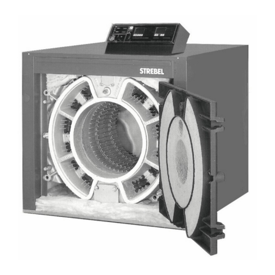
BOILER INSTALLATION INSTRUCTIONS FOR
ASSEMBLY INSTRUCTIONS
General Instructions:
The STREBEL RU boilers are special boilers for oil or gas-fired
(forced) burners. They can be fitted in hot-water heating
installations.
Operating Conditions:
Hot-water Heating installations boiler
Maximum Heat limit Temperature 110ºC / 130ºC
Operating excess pressure normal working 4 bar
Operating excess pressure multi-storey working 6 bar
Please note all relevant instructions when assembling the boilers
The Installation: The connecting and initial setting in operation
should be carried out by a qualified heating specialist.
The boiler base is to be constructed in accordance with our
diagrams.
THERE IS A STOP NUT BETWEEN THE BOILER DOOR AND THE DOOR SEAL
(TO PROTECT THE DOOR SEAL DURING TRANSIT)
THIS NUT MUST BE REMOVED ON SITE.
IMPORTANT
RU 1S / BRU 1
RU 2S / BRU 2
RU 3S
11/07/00
Advertisement
Table of Contents

Related Manuals for Strebel RU 1S Series


Summary of Contents for Strebel RU 1S Series
- Page 1 RU 1S / BRU 1 RU 2S / BRU 2 RU 3S ASSEMBLY INSTRUCTIONS General Instructions: The STREBEL RU boilers are special boilers for oil or gas-fired (forced) burners. They can be fitted in hot-water heating installations. Operating Conditions: Hot-water Heating installations boiler Maximum Heat limit Temperature 110ºC / 130ºC...
-
Page 2: Table Of Contents
ASSEMBLY INSTRUCTIONS FOR: CONTENTS: Page : Assembly instructions & tools Boiler base details & Important assembly advice Wall clearance dimensions Pulling up sections Pulling up sections Positioning & Influence of baffles Diagram of RU1 injector tube Fitting the flue-gas collector hood Fitting the rear wall protective refractory Converting the burner door hinge Assembly of boiler connections... -
Page 3: Assembly Instructions & Tools
ASSEMBLY INSTRUCTIONS FOR: ASSEMBLY INSTRUCTIONS FOR: RU 1s Assembly ASSEMBLY INSTRUCTIONS Please follow the installation instructions very carefully. The installation of all RU and BRU boilers are very similar through the RU 1, RU 2, RU 3, & BRU 1, & BRU 2. For all installations please follow the instructions for the RU1 model and, if installing the RU 2 or RU 3 models, refer to the relevant information in the appendix at the rear of this... -
Page 4: Boiler Base Details & Important Assembly Advice
ASSEMBLY INSTRUCTIONS FOR: ASSEMBLY INSTRUCTIONS FOR: RU 1s Assembly Boiler base Base Dimensions The boiler base is to be constructed in accordance with the base plans. The boiler block may stand on an iron frame set in concrete but is not essential. The boiler must stand on a level non-combustible base which is capable of adequately supporting the weight of the boiler, water content and any ancillary equipment. -
Page 5: Wall Clearance Dimensions
ASSEMBLY INSTRUCTIONS FOR: ASSEMBLY INSTRUCTIONS FOR: RU 1s Assembly WALL CLEARANCE DIMENSIONS KEY: A = Boiler length + min. 200mm B = Projection of burner + min. 100mm Page 5 11/07/00... -
Page 6: Pulling Up Sections
ASSEMBLY INSTRUCTIONS FOR: ASSEMBLY INSTRUCTIONS FOR: RU 1s Assembly Driving Nipple into Boring Stage 1: Drive nipple into nipple port with care Inspect nipple and nipple port for damage. Smear nipple jointing oil sealing compound over nipple and boring. Gently drive nipple into flow and return nipple ports using a mallet or synthetic hammer. -
Page 7: Pulling Up Sections
ASSEMBLY INSTRUCTIONS FOR: ASSEMBLY INSTRUCTIONS FOR: RU 1s Assembly Assembly of the boiler block from individual sections Assembling boiler block (NB: White section) Starting with the rear section to the front, the boiler block is assembled on the boiler base, or on the boiler base sound reducing framework. -
Page 8: Positioning & Influence Of Baffles
ASSEMBLY INSTRUCTIONS FOR: ASSEMBLY INSTRUCTIONS FOR: RU 1s Assembly Positioning the baffles Push the Baffles into the flue–ways as far as the stop Fit standard equipment in accordance with table below. Flue gas temperature can be raised by removing the baffles. Positioning the Baffles Standard boilers are equipped with the following baffles. -
Page 9: Diagram Of Ru1 Injector Tube
ASSEMBLY INSTRUCTIONS FOR: ASSEMBLY INSTRUCTIONS FOR: RU 1s Assembly STREBEL RU 1s Injector tube in the STREBEL RU 1s return NOTE: Injector tube is not a requirement for the RU 2s and RU 3s boilers. Page 9 11/07/00... -
Page 10: Fitting The Flue-Gas Collector Hood
ASSEMBLY INSTRUCTIONS FOR: ASSEMBLY INSTRUCTIONS FOR: RU 1s Assembly To fit flue gas collector hood to rear section Flue-gas collector hood assembly The flue gas housing is fitted on ex works, but not sealed in place. Fitting the flue gas collector hood Dismantle flue gas collector hood (1) Cover joint of the rear section and flue gas collector hood with boiler mastic sealing strand... -
Page 11: Assembly Of Boiler Connections
ASSEMBLY INSTRUCTIONS FOR: ASSEMBLY INSTRUCTIONS FOR: RU 1s Assembly Boiler Assembly Completion Assembly of the boiler connections Fit blank flanges top and bottom at the front. Fit boiler flow header to the rear at the top and boiler return header to the rear at the bottom. Assembly of boiler connections Fit the 2 ½”... -
Page 12: Assembling The Jackets And Insulation
ASSEMBLY INSTRUCTIONS FOR: ASSEMBLY INSTRUCTIONS FOR: RU 1s Assembly To assemble the jackets and insulation Follow the number sequence. Floor insulation and side jackets 1. Floor insulation on right and left-hand side 125x440xL 2. Right and left hand side jackets 3. -
Page 13: Bru 1S Bicalor Assembly Completion
ASSEMBLY INSTRUCTIONS FOR: BRU 1s 10. Covering Rosette BRU 1 Side View BICALOR Combination Boiler Assembly Completion The BICALOR can be fitted with top mounted calorifiers of types CS 400-9, CS 500-4, CS500-6 and CS 625-8 depending on the boiler output and the hot water requirement Assembly of calorifier Fit blank flanges at the top and bottom front Fit boiler flow header to the rear at the top and boiler return... -
Page 14: Bru 1S Bicalor Jacket & Insulation Assembly
ASSEMBLY INSTRUCTIONS FOR: BRU 1s Assemble the jacket and insulation Floor insulation and boiler side jackets. 1. Floor insulation on right and left hand side 125x440xL 2. Right and left hand side jackets 3. Insulation at the bottom front 50x90x990 4. -
Page 15: Assembling The Burner
ASSEMBLY INSTRUCTIONS FOR: ASSEMBLY INSTRUCTIONS FOR: RU 1s Assembly Assembling the burner 1. The burner must be commissioned by a qualified combustion engineer. Cables and pipes for electricity and oil should be fitted flexible to allow full swing of door. 2. -
Page 16: Gas Connections
ASSEMBLY INSTRUCTIONS FOR: ASSEMBLY INSTRUCTIONS FOR: RU 1s Assembly Page 16 11/07/00... -
Page 17: Opening & Closing Burner Door
ASSEMBLY INSTRUCTIONS FOR: ASSEMBLY INSTRUCTIONS FOR: RU 1s Assembly Page 17 11/07/00... -
Page 18: Wiring Details For Control Panel
The following schematic diagram is to assist in the installation of single phase and three phase burners, when used with Strebel RU and BRU boiler instrument control panel. For full details of the instrument panel wiring refer to the relevant electrical diagrams. - Page 19 ASSEMBLY INSTRUCTIONS FOR: ASSEMBLY INSTRUCTIONS FOR: RU 2S / BRU 2S RU 2s Assembly NOTE: RU 2s does NOT have a white patch section. Boiler base details Individual approximate weights of boiler components are listed in the table below: Rear section 254 kg Intermediate section 213 kg...
- Page 20 ASSEMBLY INSTRUCTIONS FOR: ASSEMBLY INSTRUCTIONS FOR: ASSEMBLY INSTRUCTIONS FOR: RU 2S / BRU 2S RU 2S / BRU 2S RU 2s Assembly Pulling-up kit Key: Pulling-up flange at the top rear section Pulling-up flange at the bottom rear section Pulling tool for nipples Pulling-up flange for intermediate sections Pulling-up flange for front section Basic bar...
- Page 21 ASSEMBLY INSTRUCTIONS FOR: ASSEMBLY INSTRUCTIONS FOR: ASSEMBLY INSTRUCTIONS FOR: RU 2S / BRU 2S RU 2S / BRU 2S RU 2s Assembly Follow the RU 1s instructions on the baffles using data below for the RU 2s boiler are as follows: Boiler sections 2nd Pass 3rd Pass...
-
Page 22: Ru 2S Jacket Assembly 22
ASSEMBLY INSTRUCTIONS FOR: ASSEMBLY INSTRUCTIONS FOR: RU 2S / BRU 2S RU 2s Assembly Follow the number order for jacket assembly completion Page 22 11/07/00... - Page 23 ASSEMBLY INSTRUCTIONS FOR: ASSEMBLY INSTRUCTIONS FOR: RU 2S / BRU 2S RU 2s Assembly Page 23 11/07/00...
- Page 24 ASSEMBLY INSTRUCTIONS FOR: ASSEMBLY INSTRUCTIONS FOR: ASSEMBLY INSTRUCTIONS FOR: RU 3s Assembly RU 3s Boiler Assembly Boiler base details Generally the boiler assembly is similar to the assembly of the RU 1s and RU 2s boilers. Individual approximate weights of boiler components are listed in the table below: Rear section 290 kg...
- Page 25 ASSEMBLY INSTRUCTIONS FOR: ASSEMBLY INSTRUCTIONS FOR: ASSEMBLY INSTRUCTIONS FOR: RU 3s Assembly Assembly of boiler connections. Legend (Fig. 4.3) Door Tapered centre pins Door closing bolts Channel jacking bracket Hinge pins Jacking bolts Holding pins Jacking bolts Flange bolts Blank flange and joint gasket Blank flange and joint gasket Slotted hinge bracket (Fig.
- Page 26 ASSEMBLY INSTRUCTIONS FOR: ASSEMBLY INSTRUCTIONS FOR: ASSEMBLY INSTRUCTIONS FOR: RU 3S RU 3s Assembly Pulling-up kit (Fig. 8.3) Key: Pulling-up flange at the top rear section Pulling-up flange at the bottom rear section Nipple flange Pulling-up flange for intermediate setions Pulling-up flange for front section Basic bar Extension bar...
-
Page 27: Ru 3S Jacket Assembly 27
ASSEMBLY INSTRUCTIONS FOR: ASSEMBLY INSTRUCTIONS FOR: ASSEMBLY INSTRUCTIONS FOR: RU 3S RU 3s Assembly Follow the number order for jacket assembly completion Page 27 11/07/00... - Page 28 ASSEMBLY INSTRUCTIONS FOR: ASSEMBLY INSTRUCTIONS FOR: ASSEMBLY INSTRUCTIONS FOR: RU 3S RU 3s Assembly Page 28 11/07/00...
- Page 29 ASSEMBLY INSTRUCTIONS FOR: Page 29 11/07/00...
- Page 30 THE COMPANY RESERVES THE RIGHT TO CHANGE SPECIFICATIONS AND DIMENSIONS WITHOUT NOTICE STREBEL LTD 1F Albany Park Industrial Estate Frimley Road, Camberley, Surrey, GU16 7PB Telephone: 01276 685422 Fax: 01276 685405 E-mail address: info@strebel.co.uk Website: www.strebel.co.uk Page 30 11/07/00 E. & O.E...
Need help?
Do you have a question about the RU 1S Series and is the answer not in the manual?
Questions and answers