
Subscribe to Our Youtube Channel
Related Manuals for Kane 9206 Quintox


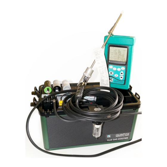
Summary of Contents for Kane 9206 Quintox
- Page 1 KANE9206 Quintox Flue Gas Analyser Stock No: 19332-5 November 2014 © Kane International Ltd...
-
Page 2: Table Of Contents
HANDSET MAIN ANALYSER UNIT OPTIONS ELECTROCHEMICAL SENSORS OTHER OPTIONS PROBE OPTIONS SPARE PARTS LIST KANE9206 WITH KANE LIVE PC SOFTWARE ANALYSER LAYOUT AND FEATURES HANDSET FEATURES ANALYSER LAYOUT ANALYSER LAYOUT WITH KMDM110/230 SAMPLE CONDITIONING UNIT FITTED TYPICAL PROBE CONFIGURATION (KMCP6) - Page 3 SETUP: CONFIGURING THE ANALYSER’S SET-UP LANGUAGE MAIN PURGE PRINTER AUTO SET TIME SET TIME SET DATE HEATER STATUS SELECT ANALYSER UNIT SERIAL NUMBER WIRELESS SET UP WIRELESS PASSKEY ANALYSER UNITS: CONFIGURES ALL THE DATA SOURCES AND SETTINGS FUEL ORIGIN FUEL TYPE EFFICIENCY GAS UNITS TEMPERATURE...
- Page 4 REPORTS: CONFIGURES REPORTS VIEW REPORTS DELETE ALL REPORTS AUTO LOG TIME START AUTO LOG START AUTO PRINTING HEADER 1 HEADER 2 FORM FEED SERVICE MANUAL AIR ZERO MANUAL PRESSURE ZERO BEFORE USING THE ANALYSER FOR THE FIRST TIME SAFETY WARNING FIRST TIME USE NORMAL START UP SEQUENCE EVERY TIME YOU USE THE ANALYSER...
- Page 5 TO START PAPER FEED CHANGING THE PRINTER RIBBON PROBLEM SOLVING HOW TO GET EXPERT HELP ANALYSER ANNUAL RECALIBRATION AND SERVICE RETURNING YOUR ANALYSER TO KANE PACKING YOUR ANALYSER SENDING YOUR ANALYSER WHEN WE RECEIVE YOUR ANALYSER SERVICE RETURNS PRODUCT SPECIFICATION...
- Page 6 ELECTROMAGNETIC COMPATIBILITY (CE) STATEMENT END OF LIFE DISPOSAL BATTERY DISPOSAL EN50379 REGULATED INSTRUCTIONS APPENDICES A. PARAMETER MEANINGS B. NOx CALCULATIONS ONLY AN NO SENSOR FITTED WORKING IN PPM: NOX REFERENCED TO NO WORKING IN MG/M3: NOX REFERENCED TO NO OR NO WORKING IN MG/M3: REFERENCED TO NO WORKING IN MG/M3: NOX REFERENCED TO NO NORMALISING READINGS...
-
Page 7: Safety Warning
It also has a USB connector to link to a PC via a cable and has an infra-red output to link to the portable Kane KMIRP-2 printer. The main analyser unit also contains significant enhancements over the KM9106. -
Page 8: Main Analyser Unit
MAIN ANALYSER UNIT: AS STANDARD KANE9206 Measures: Oxygen Carbon monoxide Ambient temperature Atmospheric pressure Inlet temperature Flue temperature Differential pressure Features: Main purge Flow control* NiMh battery packs Plain paper printer *Flow control To compensate for different suction levels in flues, hose lengths and filter contamination levels, all of which can affect the flow of sample gases, there is an active flow control system fitted to the KANE9206. -
Page 9: Options
OPTIONS: ELECTROCHEMICAL SENSORS : (UP TO 5 SENSORS) CHOOSE FROM: KNO1L/Q Nitric oxide (low range) KNO1H/Q Nitric oxide (high Range) KNO2/Q Nitrogen dioxide KSO2L/Q Sulphur dioxide (low range) KSO2H/Q Sulphur dioxide (high range) KH2S/Q Hydrogen sulphide OTHER OPTIONS: KHSA Heater for toxic sensors KHC/Q IR triple bench (CO, HC, CO KHPUR/Q... -
Page 10: Kane9206 With Kanelive Pc Software
It can be downloaded from the Kane website (www.kane.co.uk) once an analyser has been registered in the MY KANE section of the website. In the current configuration, the handset needs to be connected to the main unit by a cable and the wireless setting for the handset needs to be changed to TO PC using MENU, SETUP, WIRELESS SETUP. -
Page 11: Analyser Layout And Features
ANALYSER LAYOUT AND FEATURES HANDSET FEATURES PROTECTIVE COVER REMOTE LEAD SOCKET (8 PIN DIN) INFRA RED LED GRAPHICAL DISPLY PUMP ON/OFF KEY PRINT KEY BATTERY COMPARTMENT (BACK) ENTER KEY MENU KEY STORE KEY ON/OFF KEY SCROLL UP KEY SCROLL DOWN KEY SERIAL USB CONNECTION... -
Page 12: Analyser Layout
ANALYSER LAYOUT CONNECTION LEAD OXYGEN SENSOR FOR OXYGEN SENSOR FILTER BRIDGE OR SULPHUR FILTER WATERTRAP CONNECTION PARTICLE FILTER DUAL PRESSURE PORTS BATTERY ENCLOSURE PRINTER UNIT HANDSET (STORED IN POCKET) WATERTRAP LOCATED ON SIDE OF INSTRUMENT INSTRUMENT CASE ACCESSORY STORAGE SPACE (LEADS, WATERTRAP ETC) - Page 13 ANALYSER LAYOUT WITH KMDM110/230GAS CONDITIONING MODULE FITTED PARTICLE FILTER PRINTER UNIT HEATED LINE CONNECTION OXYGEN SENSOR GAS DRYER ASSEMBLY INSTRUMENT CASE DUAL PRESSURE PORTS WATERTRAP CONNECTION INLET SOCKET FLUE SOCKET AUX CONNECTOR OXYGEN SENSOR (25 PIN 'D') CONNECTOR CHARGER INPUT SOCKET ANALYSER 'ON' SWITCH RED POWER LED REMOTE HANDSET...
-
Page 14: Typical Probe Configuration (Kmcp6)
TYPICAL PROBE CONFIGURATION (KMCP6) THERMOCOUPLE CONNECTION (FLUE) INLET SOCKET FOR OPTIONAL AIR TEMPERATURE PROBE DEPTH STOP CONE WATERTRAP LOCATED ON SPIGOT IN CASE PROBE GAS CONNECTION TO WATERTRAP SAMPLING PROBE... -
Page 15: Analyser Connections
ANALYSER CONNECTIONS AUX CONNECTOR(25 PIN 'D') ANALYSER 'ON' SWITCH INLET SOCKET REMOTE HANDSET CONNECTION (8 PIN DIN) FLUE SOCKET RED POWER LED OXYGEN SENSOR CHARGER INPUT SOCKET CONNECTOR DUAL PRESSURE PORTS (8 PIN DIN) -
Page 16: Getting Started
To charge the handset; connect the handset to the main analyser unit using its cable. Whilst switched off, but charging, the display will show the Kane logo and a battery charging icon in the bottom right hand corner of the handset screen. Note: the handset battery is charged via the external battery charger and not from the analyser’s internal... -
Page 17: Menu: All The Options
MENU: ALL THE OPTIONS Press the MENU key. ----------------------------------MENU--------------------------------- > STATUS SETUP ANALYSER UNITS CO ALARM SCREEN REPORTS SERVICE MANUAL AIR ZERO MANUAL PRESSURE ZERO 11:33:56 23/03/13 > symbol acts as the cursor. It can be moved up or down by pressing the UP or DOWN keys. -
Page 18: Status: Establishing The Analyser'sset-Up
STATUS: ESTABLISHING THE ANALYSER'S SET-UP Press MENU and then select STATUS by pressing ENTER. ----------------------------------MENU--------------------------------- HANDSET SW19170 V1.01 SERIAL NO. 999999107 ANALYSER SW19171 V1.01 SERIAL NO, 999999207 MAIN BATTERY HEATER BATTERY 100% CAL DATE = 331 11:33:56 23/03/13 This screen lists : the software version in the handset ... - Page 19 Press DOWN to move to the next screen. ----------------------------------MENU--------------------------------- REFERENCE O2 = 3.0% NOx CALCULATION = SUM REFERENCE NOx = 5% EFFICIENCY = NET FUEL = NATURAL GAS FUEL SOURCE = UK CO ALARM SET = NO CO ALARM LEVEL = 400ppm 11:33:56 23/03/13...
-
Page 20: Setup: Configuring The Analyser'sset-Up
SETUP: CONFIGURING THE ANALYSER’S SETUP ----------------------------------MENU--------------------------------- > LANGUAGE MAIN PURGE PRINTER AUTO SET TIME SET TIME SET DATE HEATER STATUS SELECT ANALYSER BOX SERIAL No. WIRELESS SETUP WIRELESS PASS KEY BACK 11:33:56 23/03/13 LANGUAGE: Align cursor using UP or DOWN keys, then press ENTER. Use UP or DOWN keys to scroll through the selection. -
Page 21: Main Purge
MAIN PURGE: ----------------------------------MENU--------------------------------- > AUTO PURGE MAIN PURGE DURATION TIME MAIN PURGE INTERVAL TIME AUTO ZERO CAL AUTO PUMP FLOW BACK 11:33:56 23/03/13 AUTO PURGE: Set YES or NO AUTO PURGE DURATION TIME: Set fresh air purge duration to between 2 and 30 minutes MAIN PURGE INTERVAL TIME : Set the interval between fresh air purges to... -
Page 22: Auto Set Time
The choices of outputs are: KANEIRP KANEIRP-2 ANALYSER PRINTER SERIAL WIRELESS Use UP or DOWN keys to scroll through the selection. Press ENTER to select. AUTO SET TIME: This function is locked off if reports have been stored. To allow the function to operate, delete the reports. -
Page 23: Set Date
SET DATE: This function can only be set manually, not by GPS. If this function is locked, delete the reports. ----------------------------------MENU--------------------------------- SET DATE DD:MM:YY 26:04:13 11:33:56 23/03/13 If manual setting is enabled use UP or DOWN keys to change values. Press ENTER to select. -
Page 24: Wireless Set Up
WIRELESS SET UP: The handset can communicate with an analyser unit or a PC. Wireless can also be switched off and a cable can be used. Use UP or DOWN keys to scroll through the selection. Press ENTER to select. WIRELESS PASSKEY: This confirms the Passkey setting. -
Page 25: Analyser Units: Configures All The Data Sources And Settings
ANALYSER UNITS: CONFIGURES ALL THE DATA SOURCES AND SETTINGS ----------------------------------MENU--------------------------------- FUEL ORIGIN FUEL TYPE EFFICIENCY GAS UNITS COMPENSATION TEMPERATURE PRESSURE SET PERCENTAGE REFERENCE O2 SET NOx CALCULATION SET COMPENSATION CONVERSION FACTORS BACK 11:33:56 23/03/13 FUEL ORIGIN: Select from a list of country specific fuel tables. Use UP or DOWN keys to scroll through the selection. -
Page 26: Gas Units
GAS UNITS: Select ppm or ppm(n) or mg/m3 or mg/m3(n). Use UP or DOWN keys to scroll through the selection. Press ENTER to select. TEMPERATURE: Allows the selection of Fahrenheit or Celsius. Use UP or DOWN keys to scroll through the selection. Press ENTER to select. PRESSURE: Allows the selection of pressure units. -
Page 27: Co Alarm
CO ALARM: ----------------------------------MENU--------------------------------- CO ALARM SET CO ALARM LEVEL BACK 11:33:56 23/03/13 CO ALARM SET: Switch the alarm ON or OFF. Use UP or DOWN keys to scroll through the selection. Press ENTER to select. CO ALARM LEVEL: Allows a specific CO level in ppm to be set as the alarm trigger point. Use UP or DOWN keys to change the digits. -
Page 28: Screen
SCREEN: The screen display is fully configurable. ----------------------------------MENU--------------------------------- CONTRAST B’LIGHT MODE LINES 1 - 6 LINES 7 - 12 LINES 13 - 18 LINES 19 - 24 LINES 25 - 30 BACK 11:33:56 23/03/13 CONTRAST: Allows the display to be darkened or lightened. Default value is 14. Use UP or DOWN keys to change the digits. -
Page 29: Lines
LINES: This feature allows users to customise the screen display to suit their own requirements. Use UP or DOWN keys to change the selection. Press ENTER to select and move to the next digit. So for Lines 1-6, the screen shows: ----------------------------------MENU--------------------------------- LINE 1 = CO 0ppm... -
Page 30: Reports: Configures Reports
REPORTS: CONFIGURES REPORTS ----------------------------------MENU--------------------------------- VIEW REPORTS DELETE ALL REPORTS AUTO LOG TIME START AUTO LOG START AUTO PRINTING HEADER 1 HEADER 2 FORM FEED BACK 11:33:56 23/03/13 VIEW REPORTS: This selection displays a 'main screen' with a LOG No near the top left hand of the display. This number can be changed using UP or DOWN and the display automatically changes. -
Page 31: Delete All Reports
DELETE ALL REPORTS: All reports can be deleted. A confirmation YES is required Use UP or DOWN keys to scroll through the selection. Press ENTER to select. AUTO LOG TIME: Automatic logging/printing can be selected for intervals between 10 seconds and 90 minutes Use UP or DOWN keys to scroll through the selection. -
Page 32: Service
SERVICE: CODE: For use by authorised service agents. CAL DATE = number of days before annual re-calibration is due. MANUAL AIR ZERO: Select this and press ENTER to initiate a fresh air purge and sensor zeroing MANUAL PRESSURE ZERO: Select this and press ENTER to re-zero the pressure sensor... -
Page 33: Before Using The Analyser For The First Time
BEFORE USING THE ANALYSER FOR THE FIRST TIME. SAFETY WARNING This analyser extracts combustion gases that may be toxic in relatively low concentrations. These gases are exhausted from the bottom of the instrument. This instrument must only be used in well ventilated locations. It must only be used by trained and competent persons after due consideration of all the potential hazards. -
Page 34: Automatic Calibration
During this sequence the analyser pumps fresh air into the sensors to allow toxic sensors to be set to zero and the oxygen sensor to be set to 20.9 %. During this sequence the handset display will show the following: KANE QUINTOX SW 19170 v1.01 SERIAL NO. - Page 35 If there is no wireless communication between the handset and the main unit the following will appear on the screen. WIRELESS COMMS ERROR TO ANALYSER UNIT REFER TO INSTRUCTIONS PRESS ENTER TO CONTINUE 11:33:56 23/03/13 Press ENTER to continue and follow the instructions. Once wireless communication is established the main measurement screen will appear:...
-
Page 36: Main Measurement Screen
MAIN MEASUREMENT SCREEN IN SMALL FONT MODE ZERO TIME 60M ----% NETT -N\F-deg C ----ppm LOSS ----- 0ppm ----- 0ppm -N\F- 0ppm CO LOSS 0ppm P INDEX 0.00% 0ppm CO/CO2 R0.0000 ----ppm EFF (G) ----% 19.98% XAIR ----% FLUE -N\F-deg C PRESSURE 0.00mbar INLET... -
Page 37: In Large Font Mode
IN LARGE FONT MODE There are 5 screens that are accessed using the UP or DOWN keys -----------------------------------MENU---------------------------------- > LINE 1= CO2 ----% LINE 2= HC ----ppm LINE 3= CO 0ppm LINE 4= NO 0ppm LINE 5= NO2 0ppm LINE 6= NOx 0ppm BACK 11:33:56... - Page 38 -----------------------------------MENU---------------------------------- > LINE 13= NETT -N\F-deg C LINE 14= LOSS ----- LINE 15= DRY ----- LINE 16= WET -N\F- LINE 17= CO LOSS LINE 18= P INDEX 0.00% BACK 11:33:56 23/03/13 -----------------------------------MENU---------------------------------- > LINE 19= CO/CO2 R0.0000 LINE 20= EFF (G) ----% LINE 21= XAIR ----%...
-
Page 39: Sampling The Flue Gas
SAMPLING THE FLUE GAS Once the automatic calibration procedure has been completed and the specific fuel has been selected the probe can be inserted into the desired sampling point. It is recommended that the sampling point be located at least two flue diameters downstream of any bend and that the probe tip is in the centre of the flue (this is normally the point of the hottest temperature). -
Page 40: Kmdm110/230 Sample Conditioning Unit
fitted. Electrochemical sensors need regular refreshing with fresh air, prefereably at around 50% RH. They also need a small percentage of oxygen to be present in the sampled gas. If there is zero oxygen the output from the sensors will decay over time (10 mins or so). In such circumstances, fresh air purge should be programmed for a 50% duty cycle every 10 minutes. - Page 41 is used. The peristaltic pump operates automatically. Always check that the drain of the peristaltic pump is clear and that there are no blockages. The peristaltic pump needs to have its flexible rotor replaced after every 1000 hours of operation. To operate efficiently the chiller needs to be well ventilated so the case lid must be removed, however the unit must be protected externally to prevent ingress of water from either the plant being tested or from rainfall.
-
Page 42: Maintenance
MAINTENANCE EMPTYING AND CLEANING THE IN-LINE WATER TRAP The water trap should be checked and emptied on a regular basis. Water vapour will condense and gather in the probe line this may move suddenly to the trap when the probe is moved. -
Page 43: Charging The Battery
CHARGING THE BATTERY It is important that the battery is charged on a regular basis. The instrument constantly powers the internal sensors and may flatten the battery if left unattended for some months. Connect the charger supplied with the instrument to the correct mains supply. Note: The correct charger type may be required for your local voltage i.e. - Page 44 Fit a new ribbon guiding the paper roll between the exposed ribbon and cartridge body. Refit printer cover.
-
Page 45: Problem Solving
The following is a list of problems that may occur on the instrument through its operating life. If the cause of the fault is not easy to identify then we advise you to contact the Kane International Service Department or an International Distributor for expert advice. -
Page 46: Analyser Annual Recalibration And Service
Hertfordshire (Tel: 01707-384834), the primary service centre for non-UK customers. By sending your analyser back to Kane for an annual service (check www.kane.co.uk for details) you have the opportunity to extend the warranty on your analyser to 5 years. -
Page 47: Returning Your Analyser To Kane
Once the analyser has been securely packed then your package is ready for shipment back to Kane. If you do not have an account with a courier company you can take your package to your local Post Office. It is advisable to send the package by Special Delivery so that it is insured and traceable while in transit. -
Page 48: Service Returns
Service Returns (Simply cut out and attach to your package) Southern Service Centre Kane International Ltd Kane House, Swallowfield Welwyn Garden City Hertfordshire AL7 1JG Northern Service Centre Kane International Ltd Gibfield Park Avenue Atherton Manchester M46 0SY Southern Service Centre... -
Page 50: Product Specification
PRODUCT SPECIFICATION UNIT Temp Measurement Resolution Range Accuracy Flue Temperature (C/F) 0-1100°C C +0.3% of reading 32-2140°F * Use high temperature probe for gases >600°C/1112°F Inlet Temperature (C/F) 0-600°C C +0.3% of reading 0-999°F Gas Measurement Resolution Range Overrange Reading Accuracy Oxygen (0 0.01%... -
Page 51: Optional Ir Module
OPTIONAL IR MODULE Hydrocarbons: Range: Overrange Accuracy Resolution 0-5,000ppm 10,000ppm +5% of reading and + 12ppm vol. 1ppm Range: Overrange Accuracy Resolution 0-20% +5% of reading and + 0.5% vol. 0.1% Range: Overrange Accuracy Resolution 0-10% +5% of reading and + 0.2% vol. 0.1% <30% Response time T90:... -
Page 52: Extension Cable
EXTENSION CABLE Specification: 8 pin DIN cable Cable lengths: 10m Standard 5-20m-Optional MAIN BATTERY AND OPTIONAL HEATER BATTERY Type: NiMH Rechargeable (12V, 2AH) Life: 8 hours from full charge Charge time: 12 hours trickle 4 hours fast charge BATTERY CHARGER Input: 100V-240V AC 60 watts Output:... -
Page 53: Kmhl3000: Heated Sample Line
KMHL3000: HEATED SAMPLE LINE Power supply: 220V ac @ maximum 300 watts KMHP1200: HEATED PROBE: KMHP1200 Power supply: 220V ac @ maximum 100 watts 1200mm insertion length, 8 mm diameter rated to 1000 KMDM110/230: SAMPLE CONDITIONING UNIT Power supply: 220 Vac @ 5 amps peak. PROBE Choose from a range of probe options. -
Page 54: Electromagnetic Compatibility (Ce) Statement
ELECTROMAGNETIC COMPATIBILITY (CE) STATEMENT This product has been tested for compliance with the following generic standards: EN 61000-6-3 : 2011 EN 61000-6-1 : 2007 and is certified to be compliant Specification EC/EMC/KI/KANE9206 details the specific test configuration, performance and conditions of use. This product complies with the EN61010 SAFETY STANDARD Safety Standard... -
Page 55: En50379 Regulated Instructions
EN 50379 REGULATED INSTRUCTIONS EN 50379 Section 4.3.3 “Instructions” defines a number of specific points that must be included in the relevant instruction manuals. The paragraph numbering below relates to that section of EN 50379. The KANE9206 is compliant the EN 50379 Part 2 as detailed in the third party approvals issued by TÜV. - Page 56 Some commonly occurring materials, vapour or gases may affect the operation of the KANE9206 in the long or the short term though in normal use Kane International Ltd is not aware of any specific issues that have affected the product. The following list...
- Page 57 Main purge interval time: 10 to 120 minutes Auto zero: Yes & No Auto pump flow: Yes & No Printer: KANE IRP, KANE IRP-2, Serial, Wireless, Analyser printer Auto set time: Yes & No Set time: 00:00:00 to 23:59:59 Set date:...
- Page 58 Display Lines (1 to 30): Analyser main battery, Analyser heater battery, CO2 reading, HC reading, CO reading, NO reading, NO2 reading, NOx reading, SO2 reading, H2S reading, O2 reading, flue temperature reading, inlet temperature reading, ambient temperature reading, nett temperature reading, total loss reading, dry loss reading, wet loss reading, CO loss reading, poison index reading, CO_CO2 ratio reading, efficiency reading, excessive air reading, pressure...
-
Page 60: Appendices
APPENDICES A – PARAMETER MEANINGS The parameters and their meanings are detailed as follows : - DATE : Analyser date. TIME : Analyser time. MAIN BATTERY/ Displays the battery level from 0-100%. The analyser will flash HEATER BATTERY: RECHARGE BATTERY at less than 10 % of charge. The analyser may show levels greater than 100% when the charger is connected. - Page 61 Oxygen reading in percentage %. CO : Carbon monoxide reading indicated in ppm or mg/m3. If the figures are referenced to oxygen then the display will show ppmn or mg/m3n. Note with a high CO sensor fitted the reading will be displayed in percentage %.
- Page 62 PRESSURE: Pressure reading. Units can be changed to different scales. Nitric oxide reading in ppm or mg/m3. Displayed when nitric oxide sensor fitted. Reading can also be referenced to oxygen ppmn or mg/m3n. Nitrogen dioxide reading in ppm or mg/m3. Displayed when nitrogen dioxide sensor fitted.
-
Page 63: Nox Calculations
B. NOx CALCULATIONS ONLY AN NO SENSOR FITTED WORKING IN PPM: NOX REFERENCED TO NO The user can select the assumed NO percentage and the O normalised level then: NOx in ppm = NO in ppm multiplied by (1 + assumed NO percentage) in this setup NOx can only be displayed as NOx = NO then normalising:... -
Page 64: Working In Mg/M3: Nox Referenced To
WORKING IN mg/m NOX REFERENCED TO NO NOx in mg/m = NO in ppm multiplied by 2.05 multiplied by (1 + assumed percentage) NOx in mg/m = NO in mg/m divided by 1.34, multiplied by 2.05 and multiplied by (1 + assumed NO percentage) NORMALISING READINGS... -
Page 65: Normalising Readings
NORMALISING READINGS ppmn = initial reading in ppm multiplied by (21 minus the O setting) and then divided 2norm by (21 minus the actual O reading) mg/m n = initial reading in mg/m multiplied by (21 minus the O setting) and then 2norm divided by (21 minus the actual O reading) -
Page 66: Combustion Efficiency Calculation
C. COMBUSTION EFFICIENCY CALCULATION The efficiency calculation is based upon British Standard BS845. This identifies three sources of loss associated with fuel burning: LOSSES DUE TO FLUE GASSES: Dry Flue gas loss, Moisture and hydrogen Sensible heat of water vapour Unburned gas LOSSES DUE TO REFUSE: Combustible in ash... - Page 67 %CO 2 = (20.9 - %O m) x K2 / 20.9 Tnet = Flue Temperature - Inlet Temperature Dry flue gas loss = 20.9 x K1n x (Tnet) / K2 x (20.9 - %O Wet loss = 9 x %H 2 + %H 2 O / Qgr x [2488 + 2.1Tf - 4.2 Ti] simplified = [(9 x %H 2 + %H 2 O) / Qgr] x 2425 x [1 + 0.001 Tnet] Wet loss...
-
Page 68: Calculation Of Fuel Data
D. CALCULATION OF FUEL DATA For any fuel not specified by Kane International the net calorific value, gross calorific value and composition should be obtained from the fuel supplier. The following fuel data has been calculated with reference to the efficiency calculation. -
Page 69: Product Registration
PRODUCT REGISTRATION Please complete, detach and return to: Kane International Ltd Kane House, Swallowfield, Welwyn Garden City, Hertfordshire, AL7 1JG Your Details Name: Job Title: Company Name: Company Address 1: Address 2: Town/City: County: Postcode: Country: Phone Number: Fax Number:... - Page 70 Your feedback is important to us, please add any additional comments you would like to make with regard to your recent Kane purchase: Thank you for completing this survey. All the information we have collected is confidential. We do not sell or share data with any other company or organisation...
- Page 72 Thank you for reading this data sheet. For pricing or for further information, please contact us at our UK Office, using the details below. UK Office Keison Products, P.O. Box 2124, Chelmsford, Essex, CM1 3UP, England. Tel: +44 (0)330 088 0560 Fax: +44 (0)1245 808399 Email: sales@keison.co.uk...
Need help?
Do you have a question about the 9206 Quintox and is the answer not in the manual?
Questions and answers