
Related Manuals for Allen-Bradley CompactLogix 5480


Summary of Contents for Allen-Bradley CompactLogix 5480
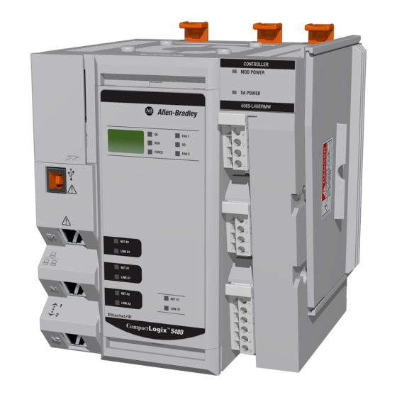
- Page 1 User Manual Original Instructions CompactLogix 5480 Controller Catalog Number 5069-L46ERMW...
- Page 2 Important User Information Read this document and the documents listed in the additional resources section about installation, configuration, and operation of this equipment before you install, configure, operate, or maintain this product. Users are required to familiarize themselves with installation and wiring instructions in addition to requirements of all applicable codes, laws, and standards.
-
Page 3: Table Of Contents
Controller Features..........15 CompactLogix 5480 System........16 Design a CompactLogix 5480 System . - Page 4 Table of Contents Set the Controller IP Address with RSLinx Classic Software . . 64 Set the Controller IP Address with the Logix Designer Application ..........66 Use a Secure Digital Card to Set the Controller IP Address .
- Page 5 Table of Contents EtherNet/IP Network Topologies ......120 DLR Network Topology ........120 Linear Network Topology.
- Page 6 Table of Contents Add to the I/O Configuration While Online ....175 Modules and Devices That Can Be Added While Online ..176 Determine When Data Is Updated .
- Page 7 Table of Contents Chapter 10 Commercial Operating System System Overview ..........211 Clock Synchronization with Logix Control Engine .
- Page 8 Table of Contents Controller Diagnostics with RSLinx Classic Software ... 256 General Tab..........256 Port Diagnostics Tab .
- Page 9 • Use of Windows 10 IoT Enterprise LTSB 64-bit operating system; referred to as the COS (commercial operating system) throughout the rest of this publication IMPORTANT The CompactLogix 5480 controller has a licensed, pre-installed COS on it. You are not required to use the COS on the controller.
-
Page 10: Preface
Controllers Reference Manual, • ControlLogix® 5560/5570 controller with a ControlLogix® 5580 publication 1756-RM100 controller • CompactLogix 5370 L3 controllers with a CompactLogix 5480 controller Compact 5000 Digital I/O Modules, Provides information on how to install, configure, and operate Compact publication 5000-UM004 5000 digital I/O modules. - Page 11 Preface Table 1 - Additional Resources Resource Description Integrated Motion on the EtherNet/IP Reference descriptions of the AXIS_CIP_DRIVE attributes and the Network Reference Manual, Logix Designer application Control Modes and Methods publication MOTION-RM003 Electronic Keying in Logix5000 Describes how to use electronic keying in Logix5000™ control systems. Control Systems Application Technique, publication LOGIX-AT001...
- Page 12 Preface Notes: Rockwell Automation Publication 5069-UM002A-EN-P - January 2019...
-
Page 13: Compactlogix 5480 System
Secure Digital (SD) Card Replaceable Fans This chapter describes a CompactLogix™ 5480 system. The CompactLogix 5480 controller has minimum programming software and Minimum Requirements firmware revision requirements. For example, you must use Studio 5000 Logix Designer® application, version 32.00.00 or later with the controller. -
Page 14: Software Application Requirements
CompactLogix 5480 System Software Application Requirements In addition to the Logix Designer application requirement, there are other minimum software version requirements in a CompactLogix 5480 system. If a CompactLogix 5480 system does not meet the minimum requirements, it does not work. -
Page 15: Controller Features
CompactLogix 5480 System Chapter 1 Controller Features Table 2 describes features available on CompactLogix 5480 controllers. Table 2 - CompactLogix 5480 Controller Features Feature Description Onboard memory Logix control engine: 20 MB Windows 10 (commercial operating system on controller): • RAM - 6 GB •... -
Page 16: Compactlogix 5480 System
Chapter 1 CompactLogix 5480 System CompactLogix 5480 System The CompactLogix 5480 system is a DIN rail-mounted system that is part of the Logix 5000 family of controllers. The controllers can operate in various applications, for example, standalone systems that include local Compact 5000™ I/O modules, as shown in... - Page 17 The controller can also operate in more complex systems with devices that are connected to the controller via an EtherNet/IP network, as shown in Figure Figure 2 - CompactLogix 5480 Controller in a More Complex System CompactLogix 5480 Controller Compact 5000™ I/O Standard Modules Compact 5000 I/O EtherNet/IP™...
-
Page 18: Design A Compactlogix 5480 System
CompactLogix 5480 System Design a CompactLogix 5480 Table 3 describes components that are used when you design a CompactLogix 5480 control system. System Table 3 - Components in a CompactLogix 5480 System Component Purpose Required For More Information DIN rail... - Page 19 CompactLogix 5480 System Chapter 1 Table 3 - Components in a CompactLogix 5480 System Component Purpose Required For More Information Ethernet ports A1 and A2 Connect to device-level network — Chapter 6, Connect to Different EtherNet/IP Network Levels on page 127...
-
Page 20: Power The System
Chapter 1 CompactLogix 5480 System Power the System The CompactLogix 5480 controller provides power to the system as follows: • MOD Power - System-side power that powers the CompactLogix 5480 system and lets modules transfer data and execute logic. System-side power is connected via the MOD power RTB. -
Page 21: Mod Power
For example, if separate external power supplies are used and SA power is lost, MOD power remains available for the CompactLogix 5480 controller and Compact 5000 I/O modules. - Page 22 Chapter 1 CompactLogix 5480 System • The total continuous current draw across the MOD power bus must not be more than 10 A, max, at 18...32V DC. IMPORTANT The controller itself draws 4 A at 18…32V DC and passes 6 A at 18…32V DC to the local I/O modules.
-
Page 23: Sa Power
TD001. SA Power SA power provides power to devices that are connected to some of the Compact 5000 I/O modules in the CompactLogix 5480 system. SA power is connected to the controller via an SA power RTB. Remember the following: •... - Page 24 Chapter 1 CompactLogix 5480 System • If the SA power source uses DC voltage, the total continuous current draw across the SA power bus must not be more than 10 A, max at 18…32V DC. • If the SA power source uses AC voltage, the total continuous current draw across the SA power bus must not be more than 10 A, max at 18…240V AC.
- Page 25 CompactLogix 5480 System Chapter 1 • Connections to an SA power bus use a shared common. All inputs that draw current from an SA power bus to power field-side devices have a return through circuitry to the SA - terminal on the SA power connector.
- Page 26 SA Power Bus When the SA power source is turned on, the following occurs. 1. The CompactLogix 5480 controller draws current from the SA power bus and passes the remaining current through to the next module. IMPORTANT The level of current that the controller draws from the SA power bus is negligible.
- Page 27 Track SA Power Bus Current Draw We recommend that you track the SA power bus current draw, max, per module, and collectively for the CompactLogix 5480 system. You must make sure that the Compact 5000 I/O modules that are installed on an SA power bus do not consume more than 10 A.
- Page 28 Chapter 1 CompactLogix 5480 System • System SA power bus current is calculated as each module draws SA power bus current. The calculation begins with the controller. The controller SA power bus current draw used for the calculation is 10 mA for DC power.
- Page 29 Figure 7 shows a CompactLogix 5480 system that uses a 5069-FPD field potential distributor to create a second SA power bus. Figure 7 - CompactLogix 5480 System - Create a New SA Power Bus 5069-FPD Field Potential Distributor DC INPUT...
- Page 30 Chapter 1 CompactLogix 5480 System IMPORTANT You must install DC-type modules and AC-type modules on separate SA Power bus. You use 5069-FPD field potential distributors to establish SA Power buses that are separate from the SA Power bus that the controller or adapter establishes.
- Page 31 CompactLogix 5480 System Chapter 1 • The actual current in a Compact 5000 I/O system changes based on the operating conditions at a given time. For example, the SA power bus current draw on some modules is different if all channels power field devices or half of the channels power field devices.
-
Page 32: Uninterruptible Power Supply
As a result, when power is restored, the controllers resume operation from the state that was saved. The CompactLogix 5480 controller does not have an internal energy storage module. You must connect an external uninterruptible power supply (UPS) to... - Page 33 CompactLogix 5480 System Chapter 1 Figure 8 shows a 1606-XLS240-UPS power supply that is connected to a CompactLogix 5480 controller. Figure 8 - Power Connected to UPS RTB UPS Ready 12V DC Battery FAN 1 Buffering – FORCE FAN 2...
-
Page 34: Secure Digital (Sd) Card
– Neither the controller nor the COS is shut down in an orderly manner. An SD card ships with the CompactLogix 5480 controller. It is installed in the Secure Digital (SD) Card controller behind the door on the front of the controller. -
Page 35: Replaceable Fans
CompactLogix 5480 System Chapter 1 Replaceable Fans The CompactLogix 5480 controller uses fans at the top and bottom of the controller to help maintain lower operating temperatures when the controller is operating. TIP In your Logix Designer application project, you can use the HardwareStatus object with GSV instructions to obtain status information about the fans and temperatures. - Page 36 Replacement fans are available from your local Allen-Bradley distributor or Rockwell Automation sales representative via catalog number 5069-FANKIT. The fans are labeled Fan 1 - Top and Fan 2 - Bottom.
-
Page 37: Remove The Top Fan
CompactLogix 5480 System Chapter 1 Remove the Top Fan 1. Push up on the front of the fan. TIP If the hinges do not disengage when you push up on the front of the fan, then use a screwdriver as a pry tool. -
Page 38: Install The Top Replacement Fan
Chapter 1 CompactLogix 5480 System Install the Top Replacement Fan 1. Insert the top replacement fan into the slot at the top of the controller. Make sure the tabs at the back of the fan are inserted in the holes at the back of the slot. -
Page 39: Remove The Bottom Fan
CompactLogix 5480 System Chapter 1 Remove the Bottom Fan 1. Push down on the front of the fan. TIP If the hinges do not disengage when you push down on the front of the fan, then use a screwdriver as a pry tool. -
Page 40: Install The Bottom Replacement Fan
Chapter 1 CompactLogix 5480 System Install the Bottom Replacement Fan 1. Insert the bottom replacement fan into the slot at the bottom of the controller. Make sure the tabs at the back of the fan are inserted in the holes at the back of the slot. -
Page 41: Connect To The Controller
Chapter Connect to the Controller Topic Page Out-of-box State Configure EtherNet/IP and USB Drivers on Your Workstation Connection Options Set the Controller IP Address Update Controller Firmware This chapter describes how to connect to the CompactLogix™ 5480 controller before you use it. IMPORTANT The content in this chapter describes how to connect to the controller to use the Logix control engine. -
Page 42: Out-Of-Box State
Chapter 2 Connect to the Controller Out-of-box State The following conditions apply when the CompactLogix 5480 controller is in the out-of-box state: • EtherNet/IP™ mode is Dual-IP mode. For more information on the EtherNet/IP mode options, see Chapter 6, Connect to Different EtherNet/IP Network Levels on page 127. -
Page 43: Configure Ethernet/Ip And Usb Drivers On Your Workstation
Connect to the Controller Chapter 2 Configure EtherNet/IP and Before you can connect to the controller through the Ethernet or USB port, you must configure the EtherNet/IP or USB driver in Linx-based software on USB Drivers on Your your workstation. Workstation A workstation running the Studio 5000 Logix Designer application can use these communication drivers:... -
Page 44: Configure The Ethernet/Ip Communication
Chapter 2 Connect to the Controller Configure the EtherNet/IP Communication Driver in RSLinx Classic Software Before you add an Ethernet driver, confirm that the following conditions exist: • The workstation is properly connected to the EtherNet/IP network. • The workstation IP address and other network parameters are configured correctly. - Page 45 Connect to the Controller Chapter 2 The Add New RSLinx Driver dialog box appears. 4. You can use the default name for the new drive or type a new name, and click OK. The Configure driver dialog box appears. 5. Click Browse Local Subnet. TIP To view devices on another subnet or VLAN from the workstation running RSLinx Classic software, click Browse Remote Subnet.
-
Page 46: Classic Software
Chapter 2 Connect to the Controller The new driver is available on the Configure Drivers dialog box. Configure the Ethernet Devices Drivers in RSLinx Classic Software The following conditions must exist to configure an Ethernet devices driver: • The workstation is connected to another Ethernet network than the target controller. - Page 47 Connect to the Controller Chapter 2 The Configure Drivers dialog box appears. 2. From the Available Driver Types pull-down menu, choose Ethernet devices. 3. Click Add New. The Add New RSLinx Driver dialog box appears. 4. You can use the default name for the new drive or type a new name, and click OK.
- Page 48 Chapter 2 Connect to the Controller The Configure driver dialog box appears. 5. On the Configure driver dialog box, enter a host name for each station to which RSLinx Classic software browses. The host name is the IP address for the device. 6.
-
Page 49: Configure The Usb Communication Driver
Configure the USB Communication Driver You must use RSLinx Classic software, version 4.10.00 or later, or FactoryTalk Linx software, version 6.10.00, with the CompactLogix 5480 controller. A USB driver automatically appears in the software when you connect the USB cable from your workstation to the controller. Once the cable is disconnected, the driver disappears from the software. - Page 50 Chapter 2 Connect to the Controller 3. Click Install the software automatically (Recommended) and click Next. The software is installed. 4. Click Finish to configure your USB driver. 5. In RSLinx Classic software, from the Communications pull-down menu, choose RSWho. The USB Port Driver appears.
-
Page 51: Connection Options
Connect to the Controller Chapter 2 Connection Options Before you can use the controller, you must connect one of the following: • Ethernet cable to an Ethernet port - The controller Ethernet ports support communication rates of 10 Mbps, 100 Mbps, and 1 Gbps. •... -
Page 52: Connect A Usb Cable
Chapter 2 Connect to the Controller Connect a USB Cable Use the USB connection to update firmware and download programs. ATTENTION: The USB port is intended only for temporary local programming purposes and not intended for permanent connection. The USB cable is not to exceed 3.0 m (9.84 ft) and must not contain hubs. WARNING: Do not use the USB port in hazardous locations. -
Page 53: Set The Controller Ip Address
For more information on how the EtherNet/IP modes affect the controller IP address, see page 131. Multiple Ethernet Ports on Controller The CompactLogix 5480 controller offers the following Ethernet ports to use the Logix control engine side of the controller: • A1 • A2 • B1 IMPORTANT The controller also has Ethernet port X1. - Page 54 Chapter 2 Connect to the Controller When the controller is in the out-of-the-box state, the following apply regarding IP addresses: • The Ethernet ports are DHCP-enabled. That is, the Ethernet ports are configured to obtain an IP address via a DHCP server. If there is no DHCP server or the DHCP server is not configured to set the IP address, you must set the IP address manually.
-
Page 55: Set The Ip Address With The Bootp-Dhcp Ethernet/Ip Commissioning Tool
Set the IP Address with the BOOTP-DHCP EtherNet/IP Commissioning Tool The Ethernet ports on a CompactLogix 5480 controllers are DHCP-enabled by default. The BOOTP-DHCP tool is a standalone tool that you can use to set an IP address. - Page 56 Chapter 2 Connect to the Controller To set the IP address with a BOOTP-DHCP tool, complete the following steps. 1. Connect your workstation to the Ethernet network where the controller resides. 2. Start the BOOTP-DHCP tool. The MAC address of the controller appears in the Request History window.
- Page 57 Connect to the Controller Chapter 2 The New Entry dialog box appears. 4. Type an IP address, Hostname, and Description for the module. Hostname and Description are optional. 5. Click OK. IMPORTANT If your controller is operating in Dual-IP mode, you must set an IP address for each controller Ethernet port.
-
Page 58: Disable Bootp/Dhcp With The Bootp-Dhcp
Chapter 2 Connect to the Controller Disable BOOTP/DHCP with the BOOTP-DHCP EtherNet/IP Commissioning Tool After an IP address is assigned to the controller, we recommend that you disable BOOTP/DHCP. Click Disable BOOTP/DHCP. The module now uses the assigned configuration and does not issue a BOOTP or DHCP request. -
Page 59: Disable Bootp/Dhcp With Rslinx Classic Software
Connect to the Controller Chapter 2 Disable BOOTP/DHCP with RSLinx Classic Software To disable BOOTP/DHCP from RSLinx Classic software, complete the following steps. 1. Start RSLinx Classic software. After several seconds, an RSWho dialog box appears. 2. If no RSWho dialog box appears, from the Communications pull-down menu, choose RSWho. - Page 60 Chapter 2 Connect to the Controller 5. On the Port Configuration tab, click Manually configure IP settings for the port, and click OK. Rockwell Automation Publication 5069-UM002A-EN-P - January 2019...
-
Page 61: Set The Controller Ip Address With The Dhcp Server
Connect to the Controller Chapter 2 Set the Controller IP Address with the DHCP Server Because the CompactLogix 5480 controllers are DHCP-enabled when they are in the out-of-box condition, you can use a DHCP server to set the IP address. - Page 62 Chapter 2 Connect to the Controller Duplicate IP Address Detection The controller verifies that its IP address does not match any other network device IP address when you perform either of the following tasks: • Connect the controller to a EtherNet/IP network. •...
- Page 63 Connect to the Controller Chapter 2 DNS Addressing You can also use DNS addressing to specify a host name for a controller, a domain name, and DNS servers. DNS addressing makes it possible to configure similar network structures and IP address sequences under different domains.
-
Page 64: Set The Controller Ip Address With Rslinx Classic Software
Chapter 2 Connect to the Controller Set the Controller IP Address with RSLinx Classic Software Complete the following steps to use RSLinx Classic software to set the controller IP address when it is in the out-of-box state. 1. Confirm that your computer is connected to the controller via a USB cable. - Page 65 Connect to the Controller Chapter 2 6. On the Port Configuration tab, click Manually configure IP settings for the port. 7. Assign the port configuration parameters and click OK. Rockwell Automation Publication 5069-UM002A-EN-P - January 2019...
-
Page 66: Set The Controller Ip Address With The Logix Designer
Chapter 2 Connect to the Controller Set the Controller IP Address with the Logix Designer Application IMPORTANT You must install firmware on your controller before you can use the Logix Designer application to set the controller IP address. Complete the following steps to use the Logix Designer application to set the controller IP address when it is in the out-of-box state. - Page 67 Connect to the Controller Chapter 2 7. When the Connected To Go Online dialog box appears, click Download. 8. When the Download dialog box appears, click Download. Rockwell Automation Publication 5069-UM002A-EN-P - January 2019...
-
Page 68: Use A Secure Digital Card To Set The Controller Ip Address
Chapter 2 Connect to the Controller 9. On the Online toolbar, click the Controller Properties icon. 10. On the Internet Protocol tab, choose the port from the Port pull-down menu. 11. Click Manually configure IP settings, enter the necessary values, and click Apply. -
Page 69: Update Controller Firmware
Connect to the Controller Chapter 2 Update Controller Firmware In the out-of-box state, the controller uses firmware revision 1.xxx. You must update the firmware revision before you can use it in a Logix Designer application project and before you can use the COS. Future firmware updates do not impact COS use. - Page 70 Chapter 2 Connect to the Controller Determine Required Controller Firmware IMPORTANT The controller must be in Remote Program or Program mode and all major recoverable faults must be cleared to accept updates. The firmware major revision level must match the software major version level. For example, if the controller firmware revision is 32.011, you must use the Logix Designer application, version 32.
- Page 71 Chapter 2 Use ControlFLASH or ControlFLASH Plus Software to Update Controller Firmware Only IMPORTANT You must use ControlFLASH software, version 15.01.00 or later, or ControlFLASH Plus, version 1.01.00 or later, with CompactLogix 5480 controllers. The software is available as follows: •...
- Page 72 Chapter 2 Connect to the Controller 3. Click Next. 4. Select the controller, and click Next. Rockwell Automation Publication 5069-UM002A-EN-P - January 2019...
- Page 73 Connect to the Controller Chapter 2 5. Expand the network driver to find the controller. 6. Select the controller and click OK. 7. Select the firmware revision and click Next. Rockwell Automation Publication 5069-UM002A-EN-P - January 2019...
- Page 74 Chapter 2 Connect to the Controller TIP If you experience a Script File Error after you select the firmware revision number, as shown, there can be a problem with your firmware files. We recommend that you use the latest version of the ControlFLASH software.
- Page 75 WARNING: Let the firmware update complete before you cycle power or otherwise interrupt the update. IMPORTANT If the firmware update is interrupted, the CompactLogix 5480 controller reverts to boot firmware, that is, revision 1.xxx. When the update is complete, the Update Status dialog box indicates that the update is complete.
- Page 76 Chapter 2 Connect to the Controller Use AutoFlash to Update Firmware To update the controller firmware with the AutoFlash feature, complete the following steps. ATTENTION: If the Secure Digital Card is locked and set to load on power-up, this update can be overwritten by firmware on the SD card. 1.
- Page 77 Connect to the Controller Chapter 2 5. On the Choose Firmware Revision dialog, browse to the location of the firmware files. 6. Select the firmware revision, and click Update. 7. On the Confirmation dialog, click Yes. 8. On the ControlFlash Attention dialog, click OK. The firmware update begins.
-
Page 78: Windows Kit
Chapter 2 Connect to the Controller Download Controller Firmware Files as Part of the Windows Kit You can download controller firmware as part of the Windows kit that is also available at the PCDC. http://compatibility.rockwellautomation.com/Pages/home.aspx The file not only provides you with the latest controller firmware revision but also the Windows files necessary to install the latest Operating System installer on your controller. -
Page 79: Start To Use The Controller
Chapter Start to Use the Controller Topic Page Create a Logix Designer Application Project Go Online with the Controller Download a Project to the Controller Upload from the Controller Choose the Controller Operation Mode Change Controller Configuration Use the Reset Button Disable the Ethernet Ports This chapter describes how to use the CompactLogix™... - Page 80 Chapter 3 Start to Use the Controller 2. Click New Project. 3. On the New Project dialog box, complete the following steps: a. Select the controller. b. Name the project. c. Browse to the location where the project file is created. d.
- Page 81 Start to Use the Controller Chapter 3 4. Select the following: • Revision • Security Authority (optional) • Secure With (only available if Security Authority is used) 5. Click Finish. Rockwell Automation Publication 5069-UM002A-EN-P - January 2019...
-
Page 82: Go Online With The Controller
Chapter 3 Start to Use the Controller Go Online with the Controller To go online with the controller, you must first specify a communication path in the Logix Designer application. TIP In this section, an Ethernet port is the communication path. You can also use the USB port. - Page 83 Start to Use the Controller Chapter 3 5. After you choose the communication path, click Go Online in the Who Active dialog box. IMPORTANT If you are going online with the controller for the first time, you must download the project. Click Download on successive dialog boxes.
-
Page 84: Use A Recent Communications Path To Go Online
Chapter 3 Start to Use the Controller Use a Recent Communications Path to Go Online You can also select a recent communications path and go online or apply it to your project. 1. Click the Recent Communications Path icon next to the Path bar. 2. -
Page 85: Download A Project To The Controller
Start to Use the Controller Chapter 3 Download a Project to When you download a project to the controller, it copies the project from the Logix Designer application onto the controller. You can download a project in the Controller two ways: •... -
Page 86: Use The Controller Status Menu To Download
Chapter 3 Start to Use the Controller 2. Read the warnings in the Download dialog box and click Download. Use the Controller Status Menu to Download After you choose a communication path in the Logix Designer application, you can use the Controller Status menu to download to the controller. From the Controller Status menu, choose Download. -
Page 87: Upload From The Controller
Start to Use the Controller Chapter 3 Upload from the Controller When you upload a project from the controller, it copies the project from the controller to the Logix Designer application. To upload a project, use one of the following methods: •... - Page 88 Chapter 3 Start to Use the Controller 4. On the Connected to Upload dialog box, verify that the project is the one you want to upload. 5. Click Upload. For more information on the Connected To upload dialog box, see the Logix Designer application online help.
-
Page 89: Use The Controller Status Menu To Upload
Start to Use the Controller Chapter 3 Use the Controller Status Menu to Upload After you establish a communication path in the Logix Designer application, you can use the Controller Status menu to upload from the controller. 1. From the Controller Status menu, choose Upload. 2. -
Page 90: Choose The Controller Operation Mode
Chapter 3 Start to Use the Controller Choose the Controller Table 6 as a reference when determining the controller operation mode. Operation Mode Table 6 - Controller Operation Mode Considerations Mode Available Controller Modes In This Mode You Can: In This Mode You Cannot: ATTENTION: Run mode—The controller is actively •... -
Page 91: Use The Mode Switch To Change The Operating Mode
• Remote (REM) • Program (PROG) FAN 1 Mode Switch FORCE FAN 2 PROG NET B1 LINK B1 NET A1 LINK A1 NET A2 SPEED X1 LINK A2 LINK X1 CompactLogix 5480 ™ Rockwell Automation Publication 5069-UM002A-EN-P - January 2019... -
Page 92: Use The Logix Designer To Change The Operating Mode
Chapter 3 Start to Use the Controller Use the Logix Designer to Change the Operating Mode To change the operating mode with the Logix Designer application, the controller is online and the mode switch is in the REM position. The following modes are available: •... -
Page 93: Change Controller Configuration
Start to Use the Controller Chapter 3 Change Controller After the project is created, you can change some configuration parameters on the Controller Properties dialog box while the controller is offline. Configuration Examples of configurable parameter that you can change offline include the following: •... -
Page 94: Use The Reset Button
NET A2 SPEED X1 LINK A2 LINK X1 CompactLogix 5480 ™ The controller power state determines whether the Logix control engine or the COS is affected. • To cause a controller reset, push in the reset button before turning on power and hold it in at power-up. -
Page 95: Controller Reset
Start to Use the Controller Chapter 3 Controller Reset You can use the reset button to perform one of the following controller resets: • Stage 1 Reset • Stage 2 Reset IMPORTANT The processes to perform both controller reset types requires that you press the reset button and hold it in place during the controller power-up sequence. - Page 96 Chapter 3 Start to Use the Controller • Does not let the controller load firmware from the SD card on the initial startup after the reset. The prevention occurs regardless of the SD card settings and without modifying the SD card contents, regardless of the write-protect setting. If configured to do so, an SD card reloads on subsequent powerup situations.
- Page 97 Start to Use the Controller Chapter 3 Stage 2 Reset IMPORTANT A stage 2 reset occurs only if the following conditions exist: • The controller does not contain a user application. • The current controller firmware is not a 1.xxx revision. The stage 2 reset completes the following: •...
- Page 98 Chapter 3 Start to Use the Controller To perform a Stage 2 reset, complete the following steps. IMPORTANT If you have open applications that are running on the COS, we recommend that you save any opened files before you begin this process. When you remove power from the controller, the COS shuts down and any unsaved data is lost.
-
Page 99: Cos Reset
Start to Use the Controller Chapter 3 • Download a Logix Designer application project to the controller in one of the following ways: – Download the project from the Logix Designer application - For more information, see Download a Project to the Controller on page –... -
Page 100: Disable The Ethernet Ports
Chapter 3 Start to Use the Controller Disable the Ethernet Ports You can disable either of the embedded Ethernet ports on the controller. 1. On the Online toolbar, click the Controller Properties icon. 2. On the Port Configuration tab, clear the Enable checkbox for the port that you want to disable and click Apply. -
Page 101: Use The Secure Digital Card
Chapter Use the Secure Digital Card Topic Page Store to the SD Card Load from the SD Card You use an SD card with your CompactLogix™ 5480 controller to store a copy of your project. The controller ships with an SD card installed. We recommend that you leave the SD card installed, so if a fault occurs, diagnostic data is automatically written to the card. - Page 102 Chapter 4 Use the Secure Digital Card IMPORTANT Do not remove the SD card while the controller is reading from, or writing to, the card. If you remove the card during either activity, the data on the card or controller can become corrupt. Additionally, the controller firmware at the time when the card is removed can become corrupted.
- Page 103 NET A1 SPEED X1 NET A2 LINK X1 CompactLogix 5480 ™ • If the card is installed and a fault occurs, diagnostic data is automatically written to the card. Diagnostic data helps the investigation and correction of the fault cause.
-
Page 104: Store To The Sd Card
Chapter 4 Use the Secure Digital Card • You can load the Logix Designer application project to the controller from the SD card. For more information on how to load the project from the SD card, see Load from the SD Card on page 108. - Page 105 Use the Secure Digital Card Chapter 4 5. Change the Load Image properties as needed. This table describes the available Load Image options. If You Want to Load the Project Choose This Load Image Option Notes Whenever you turn on or cycle power On Power Up •...
- Page 106 Chapter 4 Use the Secure Digital Card 6. Set the Load Mode properties according to your application requirements. If You Want the Controller to Go to This Mode after Loading Choose Menu Items Program Program (remote only) Run (remote only) 7.
- Page 107 Use the Secure Digital Card Chapter 4 9. Click Yes in the confirmation dialog box that appears. If you enabled Automatic Firmware Update, a dialog box informs you which modules are not included in the Automatic Firmware Update operation. IMPORTANT Do not remove the SD card while the controller is reading from, or writing to, the card.
-
Page 108: Load From The Sd Card
Chapter 4 Use the Secure Digital Card Load from the SD Card You can load a project to the controller from the SD card if the following conditions exist: • You have set the communication path. • The controller is online. •... -
Page 109: Controller Power-Up
Use the Secure Digital Card Chapter 4 Controller Power-up This table describes what happens at power-up when an SD card that is installed in the controller contains an image. Load Image Setting Controller Is in Out-of-box Condition Firmware > 1.xxx and Internal Nonvolatile Firmware >... -
Page 110: User-Initiated Action
Chapter 4 Use the Secure Digital Card User-initiated Action IMPORTANT You cannot load a project as described in this section if the controller currently uses firmware revision 1.xxx. That is, the firmware revision on an out-of-box controller. This table shows what happens at power-up when the SD card in the controller contains an image. - Page 111 Use the Secure Digital Card Chapter 4 2. On the Nonvolatile Memory tab, verify that the project that is listed is the correct one. TIP If no project is stored on the SD card, a message on the Nonvolatile Memory tab indicates that an image (or project) is not available.
- Page 112 Chapter 4 Use the Secure Digital Card 4. Click Load. 5. Click Yes in the confirmation dialog box that appears. After you click Yes, the project is loaded to the controller as indicated by the controller status indicators. Load Status The Following Occurs In Progress •...
-
Page 113: Other Secure Digital Card Tasks
Use the Secure Digital Card Chapter 4 Other Secure Digital Card Tasks You can use the SD cards to complete the following other tasks: • Change the image that is loaded from the card • Check for a load that was completed •... - Page 114 Chapter 4 Use the Secure Digital Card Notes: Rockwell Automation Publication 5069-UM002A-EN-P - January 2019...
-
Page 115: Ethernet/Ip Network
The CompactLogix 5480 controllers use socket interface transactions and conventional communication over the EtherNet/IP network to communicate with Ethernet devices that do not support the EtherNet/IP application protocol. -
Page 116: Ethernet/Ip Network Functionality
Chapter 5 EtherNet/IP Network EtherNet/IP Network The CompactLogix 5480 controllers support this EtherNet/IP network functionality: Functionality • Offers the following EtherNet/IP network ports – A1 – A2 – B1 • Support for the following EtherNet/IP modes: – Dual-IP mode – Linear/DLR mode •... -
Page 117: Software For Ethernet/Ip Networks
EtherNet/IP Network Chapter 5 • Compatible with industry-standard Ethernet switches - Managed switches are recommended, and CIP-protocol-aware switches can provide more predictable performance. • Support for messaging, produced/consumed tags, HMI, and distributed I/O modules • Support for Integrated Motion Over an EtherNet/IP network For more information on how to use Integrated Motion over an EtherNet/IP network, see Chapter 9, Develop Motion Applications on... -
Page 118: Nodes On An Ethernet/Ip Network
Chapter 5 EtherNet/IP Network Nodes on an EtherNet/IP When you configure your CompactLogix 5480 controller system, you must account for the number of EtherNet/IP nodes that you include in the I/O Network configuration section of your project. The CompactLogix 5480 controller supports as many as 250 EtherNet/IP nodes. -
Page 119: Rockwell Automation Publication 5069-Um002A-En-P - January
EtherNet/IP Network Chapter 5 Figure 13 - Example EtherNet/IP Nodes Node Node Node Node Node Node The Capacity tab in the Controller Properties dialog box tracks the number of Ethernet nodes that are used in a project. This graphic is representative of the project that is shown in Figure Rockwell Automation Publication 5069-UM002A-EN-P - January 2019... -
Page 120: Ethernet/Ip Network Topologies
If the controller operates in Dual-IP mode, it must connect to a DLR topology via a 1783-ETAP that is connected to an Ethernet port on the controller. Figure 14 - CompactLogix 5480 Controller in a DLR Network Topology CompactLogix 5480 Controller 5069-AEN2TR Adapter Compact 5000™... -
Page 121: Linear Network Topology
EtherNet/IP network. Devices that can connect to a linear network topology use embedded switch technology to eliminate the need for a separate switch, as required in Star network topologies. Figure 15 - CompactLogix 5480 Controller in a Linear Network Topology CompactLogix 5480 Controller 5069-AEN2TR Adapter... -
Page 122: Star Network Topology
A star network topology is a traditional EtherNet/IP network that includes multiple devices that are connected to each other via an Ethernet switch. Figure 16 - CompactLogix 5480 Controllers in a Star Network Topology CompactLogix 5480 Controller Compact 5000 I/O Modules... -
Page 123: Ethernet/Ip Network Communication Rates
1-Gbps network communication rate on a CompactLogix 5480 controller. When you design a CompactLogix 5480 system and consider using the 1-Gbps network rate on the controller, remember the following: • You can use the 1-Gbps network communication rate on the controller ports when all network devices support the 1 Gbps, for example, 5069-AEN2TR adapters with Compact 5000™... - Page 124 The port to which the controller is connected must be configured for Auto-Negotiate and support the 1-Gbps network communication rate. CompactLogix 5480 Controller Compact 5000 I/O Modules 5069-AENTR Adapter Compact 5000 I/O Modules...
- Page 125 EtherNet/IP network without a managed switch. In this example, all network communication on this network uses the 100- Mbps rate. You must set each device to a fixed speed of 100 Mbps. CompactLogix 5480 Controller 5069-AEN2TR Adapter Compact 5000 I/O Modules...
-
Page 126: Socket Interface
‘THIS’ . • All Logix 5000 controllers must use unconnected MSG instructions for socket servers. When you configure a message for a CompactLogix 5480 controller, make sure that the Connected checkbox on the Message Configuration dialog box is cleared. -
Page 127: Connect To Different Ethernet/Ip Network Levels
Software Display Differences for EtherNet/IP Modes This chapter describes the different EtherNet/IP™ network levels and how the CompactLogix™ 5480 controller can connect to them. The CompactLogix 5480 controller can connect to the following Available Network Levels EtherNet/IP network levels: • Enterprise-level network •... - Page 128 Figure 17 shows an example application in which the controller is connected to an enterprise-level network and device-level networks. Figure 17 - CompactLogix 5480 System Connected to Enterprise-level and Device-level Networks FactoryTalk® Cloud 10/100/1000 PoE+...
-
Page 129: Connect To An Enterprise-Level Network
Connect to Different EtherNet/IP Network Levels Chapter 6 Connect to an The CompactLogix 5480 controller Ethernet ports B1 and X1 can connect to an enterprise-level network. A port that is connected to an enterprise-level Enterprise-level Network network is also known as an uplink port. -
Page 130: Connect To A Device-Level Network
Chapter 6 Connect to Different EtherNet/IP Network Levels Connect to a The CompactLogix 5480 controller Ethernet ports A1, A2, and B1 can connect to device-level networks. Remember the following when you connect Device-level Network to device-level networks: • You are not required to connect the controller to an enterprise-level network to connect to device-level networks. -
Page 131: Port B1
Dual-IP Mode Dual-IP mode lets you connect port A1 and port A2 connect to separate device-level networks, that is, different subnets. The CompactLogix 5480 controller uses Dual-IP mode by default. In this mode, each port requires its own network configuration. For more... - Page 132 Chapter 6 Connect to Different EtherNet/IP Network Levels Figure 18 shows an example of a CompactLogix 5480 controller in Dual-IP mode with port B1 connected to an enterprise-level network. Figure 18 - CompactLogix 5480 Controller in Dual-IP Mode FactoryTalk Cloud...
-
Page 133: Linear/Dlr Mode
Linear/DLR mode lets you connect port A1 and port A2 to the same device-level network. IMPORTANT The CompactLogix 5480 controller is set to Dual-IP mode by default. You must change the EtherNet/IP Mode to use Linear/DLR mode. For more information on how to change the controller EtherNet/IP mode, page 144. -
Page 134: Overlapping Ip Address Ranges
Chapter 6 Connect to Different EtherNet/IP Network Levels Overlapping IP The IP address and subnet mask values that you assign to an Ethernet port establish an IP address range for the port. The Subnet mask value is used to Address Ranges establish the Network part of the IP address. - Page 135 Connect to Different EtherNet/IP Network Levels Chapter 6 This example describes conditions in which IP address ranges do overlap. EXAMPLE IP Address Ranges Do Overlap The table describes port B1 and port X1 configurations use IP address ranges that do overlap. All IP addresses in the port B1 IP address range are in the port X1 IP address range.
-
Page 136: Configure The Ethernet/Ip Modes
Chapter 6 Connect to Different EtherNet/IP Network Levels Configure the EtherNet/IP You can configure the EtherNet/IP modes with the following: • Logix Designer application Modes • RSLinx® Classic software Configure Dual-IP Mode in the Logix Designer Application In the Logix Designer application, the EtherNet/IP Mode is Dual-IP by default and is displayed on the General tab in the Controller Properties dialog box. - Page 137 Connect to Different EtherNet/IP Network Levels Chapter 6 You set the IP address and Subnet Mask on the Internet Protocol tab. TIP When you set the IP address and Subnet Mask, we recommend that you use a USB connection from the workstation to the controller. 1.
-
Page 138: Configure Dual-Ip Mode In Rslinx Classic Software
Chapter 6 Connect to Different EtherNet/IP Network Levels Configure Dual-IP Mode in RSLinx Classic Software In RSLinx Classic software, the IP Mode for which the controller is configured is displayed on the General tab in the Configuration dialog box. You set the IP Address and Network Mask on the Port Configuration tab. TIP When you set the IP address and Subnet Mask, we recommend that you use a USB connection from the workstation to the controller. - Page 139 Connect to Different EtherNet/IP Network Levels Chapter 6 2. On the Port Configuration tab, click Manually configure IP settings. 3. From the Port pull-down menu, choose A1. 4. Assign IP Address and Network Mask values, and click Apply. 5. Repeat the steps. step 1, make sure that you choose A2 from the Port pull-down menu.
-
Page 140: Configure Linear/Dlr Mode In The Logix Designer Application
Chapter 6 Connect to Different EtherNet/IP Network Levels Configure Linear/DLR Mode in the Logix Designer Application The EtherNet/IP mode is Dual-IP by default. You must change the mode to use Linear/DLR mode. For more information on how to change the controller EtherNet/IP mode, see Change the EtherNet/IP Mode on page 144. - Page 141 Connect to Different EtherNet/IP Network Levels Chapter 6 You set the IP Address and Subnet Mask on the Internet Protocol tab. 1. Confirm that the project is online. 2. Confirm that the controller is in one of the following modes: •...
-
Page 142: Configure Linear/Dlr Mode In Rslinx Classic Software
Chapter 6 Connect to Different EtherNet/IP Network Levels Configure Linear/DLR Mode in RSLinx Classic Software Remember, the EtherNet/IP Mode is Dual-IP by default. You must change the mode to use Linear/DLR mode. For more information on how to change the controller EtherNet/IP mode, see Change the EtherNet/IP Mode on page 144. - Page 143 Connect to Different EtherNet/IP Network Levels Chapter 6 You set the IP Address and Subnet Mask on the Internet Protocol tab. 1. Confirm that the project is online. 2. Right-click the controller and choose Module Configuration. 3. On the Port Configuration tab, click Manually configure IP settings. 4.
-
Page 144: Change The Ethernet/Ip Mode
Chapter 6 Connect to Different EtherNet/IP Network Levels Change the EtherNet/IP You can change the EtherNet/IP mode in the Logix Designer application or RSLinx Classic software. Mode IMPORTANT Remember the following: • Exercise caution when you change the EtherNet/IP mode on your controller, and consider the possible effects of the change. -
Page 145: Change The Ethernet/Ip Mode In The Logix Designer Application
Connect to Different EtherNet/IP Network Levels Chapter 6 Change the EtherNet/IP Mode in the Logix Designer Application IMPORTANT This example shows the EtherNet/IP mode change from Dual-IP mode to Linear/DLR mode. The same tasks apply to change from Linear/DLR mode to Dual-IP mode. - Page 146 Chapter 6 Connect to Different EtherNet/IP Network Levels 4. From the New mode pull-down menu, choose the new mode and click OK. 5. Click OK on the Controller Properties dialog box. 6. Save the project. 7. Download the updated project to the controller. 8.
-
Page 147: Change The Ethernet/Ip Mode In Rslinx Classic Software
Connect to Different EtherNet/IP Network Levels Chapter 6 Change the EtherNet/IP Mode in RSLinx Classic Software To change the EtherNet/IP mode in RSLinx Classic software, complete the following steps. 1. Confirm that the controller is online and there is no project in the controller. - Page 148 Chapter 6 Connect to Different EtherNet/IP Network Levels 4. On the General tab of the Configuration dialog box, click Change IP Mode. 5. From the New mode pull-down menu, choose the new mode and click OK. Rockwell Automation Publication 5069-UM002A-EN-P - January 2019...
- Page 149 Connect to Different EtherNet/IP Network Levels Chapter 6 6. If the following warning appears, read it carefully and click Yes to continue. IMPORTANT Before you change the EtherNet/IP mode, make sure that you understand the impact of a mode change on your controller. For more information on the impact of changing the EtherNet/IP mode, see Table 8 on page...
-
Page 150: Internet Protocol Configuration In Logix Designer Application
Chapter 6 Connect to Different EtherNet/IP Network Levels Internet Protocol Configuration in Logix Designer Application Figure 20 shows differences between Internet Protocol configurations on the controller in the Logix Designer application. Figure 20 - Differences Between Enterprise-level Port Configuration and Device-level Configuration Enterprise-level Port Device-level Port... -
Page 151: Port Configuration In Rslinx Classic Software
Connect to Different EtherNet/IP Network Levels Chapter 6 Port Configuration in RSLinx Classic Software Figure 21 shows differences between port configurations on the controller in RSLinx Classic software. Figure 21 - Differences Between Enterprise Port Configuration and Device-level Configuration Enterprise-level port Device-level port Parameters are not configured for the device-level port. -
Page 152: Controller Functionality Considerations
Chapter 6 Connect to Different EtherNet/IP Network Levels Controller Functionality Considerations Remember the following controller functions when your controller is connected to an enterprise-level network and at least one device-level network: • The controller does not support the following functions: –... -
Page 153: Smtp Server
Connect to Different EtherNet/IP Network Levels Chapter 6 DNS Request Generated From Port A1 or Port A2 • If port B1 is enabled and the DNS server address is in local subnet of port B1, DNS requests leave through B1 port. •... -
Page 154: Use Socket Object
Chapter 6 Connect to Different EtherNet/IP Network Levels Use Socket Object When the controller operates in Dual-IP mode and uses a Socket Object, you can use an IP address with a Socket_Create service type. By default this IP address is INADDR_ANY. Remember the following: •... -
Page 155: Software Display Differences For Ethernet/Ip Modes
Connect to Different EtherNet/IP Network Levels Chapter 6 Software Display Differences Table 9 shows differences in the Logix Designer application when the controller uses Dual-IP mode or Linear/DLR mode. for EtherNet/IP Modes Table 9 - EtherNet/IP Mode Display Differences in the Logix Designer Application EtherNet/IP Mode Section in Dual-IP Mode... - Page 156 Chapter 6 Connect to Different EtherNet/IP Network Levels Table 10 shows differences in RSLinx Classic software when the controller uses Dual-IP mode or Linear/DLR mode. Table 10 - EtherNet/IP Mode Display Differences in the RSLinx Classic Software EtherNet/IP Mode Section in Dual-IP Mode Linear/DLR Mode Software...
-
Page 157: Use I/O Modules
• Remote I/O modules Local I/O Modules A CompactLogix 5480 system uses Compact 5000™ I/O modules as local I/O modules. The modules are installed to the right of the controller. You can install as many as 31 local Compact 5000 I/O modules in a CompactLogix 5480 system. - Page 158 Use I/O Modules The following are example factors that you must consider when you decide how to use local I/O modules in a CompactLogix 5480 system: • Number of local I/O modules that the controller supports • Features available on different modules, for example, sequence of events...
-
Page 159: Add Local I/O Modules To A Project
Use I/O Modules Chapter 7 Add Local I/O Modules to a Project Before you can add local I/O modules to a Logix Designer application project, you must open an existing project or create a project. For information on how to create a project, see Create a Logix Designer Application Project on page There are two methods to add local I/O modules to the project: •... - Page 160 Chapter 7 Use I/O Modules 3. At the Select Module Type window, click Create to add a discovered module to your project. 4. At the New Module window, configure the module properties and click OK. 5. At the warning dialog box, click Yes. TIP If you inhibit the module connection, you must remember to uninhibit the connection later.
- Page 161 Use I/O Modules Chapter 7 To add additional local I/O modules, complete one of the following: • If you cleared the Close on Create checkbox when you created the first I/O module, repeat steps 3…6. • If you did not clear the Close on Create checkbox when you created the first I/O module, repeat steps 2…6.
- Page 162 • If you did not clear the Close on Create checkbox when you created the first I/O module, repeat steps 1…3. For more information on how to use local I/O modules in a CompactLogix 5480 system, see the resources that are listed in Additional Resources on page...
-
Page 163: Electronic Keying
Use I/O Modules Chapter 7 Electronic Keying Electronic Keying reduces the possibility that you use the wrong device in a control system. It compares the device that is defined in your project to the installed device. If keying fails, a fault occurs. The following attributes are compared. -
Page 164: Remote I/O Modules
CompactLogix 5480 system. For more information, see EtherNet/IP Network Communication Rates on page 123 Figure 23 - Remote I/O Modules in a CompactLogix 5480 System on a DLR Network Topology CompactLogix 5480 Controller 5069-AEN2TR Adapter Compact 5000 I/O Modules Compact 5000 I/O Modules... - Page 165 Use I/O Modules Chapter 7 Figure 24 - Remote I/O in a CompactLogix 5480 System on a Linear Network Topology CompactLogix 5480 Controller 5069-AEN2TR Adapter Compact 5000 I/O Modules Compact 5000 I/O Modules FAN 1 FORCE FAN 2 NET B1...
-
Page 166: Add Remote I/O Modules To A Project
Before you can add remote I/O modules to a project, you must add the EtherNet/IP communication module that facilitates communication between the CompactLogix 5480 controller and the remote I/O modules. There are two methods to add remote I/O modules to the project: •... - Page 167 Use I/O Modules Chapter 7 The tasks that are described in this section apply when you use the EtherNet/ IP driver in RSWho to browse the network. To use Discover Modules to add a remote I/O module, complete the following steps.
- Page 168 Chapter 7 Use I/O Modules 3. At the Select Module Type window, click Create to add a discovered adapter to your project. 4. At the New Module window, configure the module properties and click OK. Rockwell Automation Publication 5069-UM002A-EN-P - January 2019...
- Page 169 Use I/O Modules Chapter 7 5. At the warning dialog box, click Yes. TIP If you inhibit the module connection, you must remember to uninhibit the connection later. 6. Close the Select Module Type dialog box. 7. Right-click 5069 Backplane and choose Discover Modules. The Logix Designer application automatically detects available modules that are installed in the system.
- Page 170 Chapter 7 Use I/O Modules 8. At the Select Module Type window, click Create to add a discovered module to your project. 9. At the New Module window, configure the module properties and click OK. Rockwell Automation Publication 5069-UM002A-EN-P - January 2019...
- Page 171 Use I/O Modules Chapter 7 10. At the warning dialog box, click Yes. TIP If you inhibit the module connection, you must remember to uninhibit the connection later. 11. Close the Select Module Type dialog box. After you add the remote I/O module, consider the following: •...
- Page 172 Chapter 7 Use I/O Modules New Module To use New Module to add a remote I/O module, complete the following steps. 1. Right-click Ethernet and choose New Module. 2. Select the EtherNet/IP adapter and click Create. For some modules, the Select Major Revision dialog box can appear. If the dialog box appears, choose the major revision of the module and click OK.
- Page 173 Use I/O Modules Chapter 7 3. At the New Module window, configure the module properties and click OK. 4. Close the Select Module Type dialog box. 5. Right-click the newly added EtherNet/IP communication module or the backplane and choose New Module. Rockwell Automation Publication 5069-UM002A-EN-P - January 2019...
- Page 174 Chapter 7 Use I/O Modules 6. Select the I/O module that you want to add and click Create. TIP If you must add multiple I/O modules to the same remote location, we recommend that you clear the Close on Create checkbox before you click Create.
-
Page 175: Add To The I/O Configuration While Online
Use I/O Modules Chapter 7 9. If you want to add more remote I/O modules, complete one of the following tasks: • To add remote I/O modules in the same remote location, complete one of the following: – If you cleared the Close on Create checkbox when you created the first I/O module, repeat steps 6…7. -
Page 176: Modules And Devices That Can Be Added While Online
Manual, publication 1756-RM094. Modules and Devices That Can Be Added While Online You can add the following modules and devices to the CompactLogix 5480 controller I/O configuration while online with Logix Designer application, version 32.00.00 or later. • Compact 5000 I/O modules - As local or remote I/O modules •... -
Page 177: Determine When Data Is Updated
Use I/O Modules Chapter 7 Determine When Data CompactLogix 5480 controllers update data asynchronously with the execution of logic. See the following flowcharts to determine when a controller, Is Updated input module, or bridge sends data: • Input Data Update Flowchart •... -
Page 178: Output Data Update Flowchart
Chapter 7 Use I/O Modules Output Data Update Flowchart Automatic output processing of each task. Method of Output Data Production Output Module Profile Configuration IOT instruction executes. Cyclic data production at the RPI. Module profile lets data be Module profile lets data be sent at the RPI only sent at the RPI or at the end of task scans... -
Page 179: Develop Control Applications
Chapter Develop Control Applications Topic Page Elements of a Control Application Tasks Programs Routines Parameters and Local Tags Programming Languages Add-on Instructions Extended Properties Access the Module Object from an Add-On Instruction Monitor Controller Status Connection Overview Controller Communication Interaction with Control Data Produce and Consume (Interlock) Data Send and Receive Messages Monitor I/O Connections... - Page 180 Chapter 8 Develop Control Applications Figure 26 - Elements of a Control Application Controller Fault Handler Task 32 Task 1 Configuration Status Watchdog Program 1000 Program 1 Program Tags and Program Main Routine Parameters Fault Routine Other Routines Add-On Instruction System-shared Data I/O Data Controller (global) Tags...
-
Page 181: Tasks
Develop Control Applications Chapter 8 Tasks A Logix 5000™ controller lets you use multiple tasks to schedule and prioritize the execution of your programs based on criteria. This multitasking allocates the processing time of the controller among the operations in your application: •... - Page 182 Chapter 8 Develop Control Applications Figure 28 - Tasks Controller Organizer Logical Organizer Main Task (continuous) Main Task (continuous) Task 2 Task 2 (periodic) (periodic) A task provides scheduling and priority information for a set of one or more programs. Use the Task Properties dialog box to configure tasks as continuous, periodic, or event.
- Page 183 Develop Control Applications Chapter 8 Table 11 explains the types of tasks you can configure. Table 11 - Task Types and Execution Frequency Task Type Task Execution Description Continuous Constant The continuous task runs in the background. Any CPU time that is not allocated to other operations (such as motion and other tasks) is used to execute the programs in the continuous task.
-
Page 184: Event Task With Compact 5000 I/O Modules
Chapter 8 Develop Control Applications Event Task with Compact 5000 I/O Modules Some Compact 5000™ I/O modules can trigger an Event task. For example, complete the following steps to configure an Event task that is triggered by a state change on a 5069-IB16F module input. 1. -
Page 185: Task Priority
Develop Control Applications Chapter 8 Task Priority Each task in the controller has a priority level. The operating system uses the priority level to determine which task to execute when multiple tasks are triggered. A higher priority task interrupts any lower priority task. The continuous task has the lowest priority and a periodic or event task interrupts The continuous task runs whenever a periodic task is not running. -
Page 186: Programs
Chapter 8 Develop Control Applications Programs The controller operating system is a preemptive multitasking system that is in compliance with IEC 61131-3. This system provides the following: • Programs to group data and logic • Routines to encapsulate executable code that is written in one programming language Each program contains the following: •... -
Page 187: Scheduled And Unscheduled Programs
Develop Control Applications Chapter 8 Figure 32 - Programs Controller Organizer Logical Organizer Scheduled and Unscheduled Programs The scheduled programs within a task execute to completion from first to last. Programs that are not attached to any task show up as unscheduled programs. Unscheduled programs within a task are downloaded to the controller with the entire project. -
Page 188: Routines
Chapter 8 Develop Control Applications Routines A routine is a set of logic instructions in one programming language, such as Ladder Diagram (ladder logic). Routines provide the executable code for the project in a controller. Each program has a main routine. The main is the first routine to execute when the controller triggers the associated task and calls the associated program. -
Page 189: Parameters And Local Tags
Develop Control Applications Chapter 8 Parameters and Local Tags With a Logix 5000 controller, you use a tag (alphanumeric name) to address data (variables). In Logix 5000 controllers, there is no fixed, numeric format. The tag name identifies the data and lets you do the following: •... -
Page 190: Programming Languages
Chapter 8 Develop Control Applications Programming Languages The Logix Designer application supports the following programming languages. Language Is Best Used in Programs with Ladder Diagram (LD) Continuous or parallel execution of multiple operations (not sequenced) Boolean or bit-based operations Complex logical operations Message and communication processing Machine interlocking Operations that service or maintenance personnel have to interpret to... -
Page 191: Add-On Instructions
Develop Control Applications Chapter 8 Add-on Instructions With the Logix Designer application, you can design and configure sets of commonly used instructions to increase project consistency. Similar to the built-in instructions that are contained in Logix 5000 controllers, these instructions you create are called Add-On Instructions. Add-On Instructions reuse common control algorithms. -
Page 192: Extended Properties
Chapter 8 Develop Control Applications Extended Properties The Extended Properties feature lets you define more information, such as limits, engineering units, or state identifiers for various components within the controller project. Component Extended Properties In the tag editor, add extended properties to a tag. User-defined data type In the data type editor, add extended properties to data types. -
Page 193: Access The Module Object From An Add-On Instruction
Develop Control Applications Chapter 8 Access the Module Object The MODULE object provides status information about a module. To select a particular module object, set the Object Name operand of the GSV/SSV from an Add-On Instruction instruction to the module name. The specified module must be present in the I/O Configuration section of the controller organizer and must have a device name. -
Page 194: Monitor Controller Status
Develop Control Applications Monitor Controller Status The CompactLogix 5480 controller uses Get System Value (GSV) and Set System Value (SSV) instructions to get and set (change) controller data. The controller stores system data in objects. There is no status file, as in the PLC-5®... -
Page 195: Connection Overview
• Connected Messages are executed in the user application. • External devices, programming terminals, or HMI terminals communicate with the controller. The CompactLogix 5480 controller runs the communications task separately Controller Communication from the application code. The controller runs communications Interaction with asynchronously to the application. - Page 196 Because the controller processes communications on an independent CPU core, these methods are no longer effective in all cases. Table 13 highlights the controller behavior. Table 13 - CompactLogix 5480 Controller Behavior Tag Access Application Construct I/O Update...
-
Page 197: Produce And Consume (Interlock) Data
If you use buffered data, you prevent the risk of the communication core changing data after you have passed the data valid test. CompactLogix 5480 controllers let you produce (transmit) and consume Produce and Consume (receive) controller-scoped tags. -
Page 198: Requested Packet Interval (Rpi) Of Multicast Tags
Chapter 8 Develop Control Applications Table 15 describes the system-shared tags. Table 15 - Produced and Consumed Tag Descriptions Description Produced tag A tag that a controller makes available for use by other controllers. Multiple controllers can simultaneously consume (receive) the data. A produced tag sends its data to one or more consumed tags (consumers) without using logic. -
Page 199: Send And Receive Messages
Develop Control Applications Chapter 8 Send and Receive Messages Messages transfer data to other devices, such as other controllers or operator interfaces. The MSG instruction is a ladder logic output instruction that asynchronously reads or writes a block of data to or from another module over the backplane or a network. -
Page 200: Determine Whether To Cache Message Connections
Unconnected messages are best used for infrequent cached message connections. TIP Cached connections transfer data faster than uncached connections. The CompactLogix 5480 controller can cache as many as 256 connections. Monitor I/O Connections If communication with a device in the I/O configuration of the controller does not occur in an application-specific period, the communication times out and the controller produces warnings. -
Page 201: Determine If I/O Communication Has Timed Out
Minor, and I/O Faults Programming Manual, publication 1756-PM014. Determine If I/O Communication Has Timed Out This example can be used with the CompactLogix 5480 controllers: • The GSV instruction gets the status of the I/O status indicator (via the LEDStatus attribute of the Module object) and stores it in the IO_LED tag. -
Page 202: Module Has Timed Out
Chapter 8 Develop Control Applications Determine If I/O Communication to a Specific I/O Module Has Timed Out If communication times out with a device (module) in the I/O configuration of the controller, the controller produces a fault code and fault information for the module. -
Page 203: Sample Controller Projects
Develop Control Applications Chapter 8 You can configure the application so that a response to a failed I/O module connection can wait until the next program scan. In this case, put the logic in a normal routine and use the GSV technique that is described on page 201 call the logic. - Page 204 Chapter 8 Develop Control Applications Notes: Rockwell Automation Publication 5069-UM002A-EN-P - January 2019...
-
Page 205: Develop Motion Applications
This chapter describes how to use motion with a CompactLogix™ 5480 controller. Motion Overview CompactLogix 5480 controllers support Integrated Motion over an EtherNet/ IP™ network on digital and integrated motion interfaces. Consider the following: • The controller supports integrated axes as follows: –... -
Page 206: Motion Applications
Startup User Manual, publication MOTION-UM003. • Integrated Motion on the EtherNet/IP network Reference Manual, Publication MOTION-RM003. IMPORTANT The CompactLogix 5480 controllers do not support Analog or SERCOS motion. You can associate Integrated Motion axes to any appropriate drive. Motion Applications The following are general steps to configure a motion application. -
Page 207: Program Motion Control
Develop Motion Applications Chapter 9 Program Motion Control The controller provides a set of motion control instructions for your axes: • The controller uses the instructions just like the rest of the Logix 5000™ instructions. • Each motion instruction works on one or more axes. •... -
Page 208: Example
Chapter 9 Develop Motion Applications Example In this example, a simple ladder diagram that homes, jogs, and moves an axis. If Initialize_Pushbutton = on and the axis = off (My_Axis_X.ServoActionStatus = off), the MSO instruction turns on the axis. If Home_Pushbutton = on and the axis hasn’t been homed (My_Axis_X.AxisHomedStatus = off), the MAH instruction homes the axis. If Jog_Pushbutton = on and the axis = on (My_Axis_X.ServoActionStatus = on), the MAJ instruction jogs the axis forward at 8 units/second. -
Page 209: Obtain Axis Information
Develop Motion Applications Chapter 9 Obtain Axis Information You can obtain axis information via the following methods: • Double-click the axis to open the Axis Properties dialog box. • Use a Get System Value (GSV) or Set System Value (SSV) instruction to read or change the configuration at runtime. -
Page 210: Rockwell Automation Publication 5069-Um002A-En-P - January
Chapter 9 Develop Motion Applications Notes: Rockwell Automation Publication 5069-UM002A-EN-P - January 2019... -
Page 211: System Overview
• The COS is licensed and pre-installed on the controller. • You are not required to use the COS. • You cannot extend CompactLogix 5480 controller real-time control to the COS. • You must update the controller firmware revision to a working revision level, that is, firmware revision 32.011 or later, before the COS can start. -
Page 212: Clock Synchronization With Logix Control Engine
Chapter 10 Commercial Operating System TIP If you are not using the COS, consider shutting it down because there is no benefit to running the COS if it is not in use. There are benefits to shutting down the COS if you are not going to use it, though. -
Page 213: Memory Dedicated To Windows-Based Activities
Controller Reset Causes COS Reset The CompactLogix 5480 controller is an industrial controller that hosts the COS. When the controller resets, power is cycled to the controller, and the COS resets. -
Page 214: Ports Dedicated To Windows-Based Activities
The following ports are available on the bottom of the controller to use with the COS: • Ethernet Port X1 • USB 3.0 Host Ports • DisplayPort Figure 45 - COS Ports on a CompactLogix 5480 Controller L IN L IN L IN Ethernet Port X1 ™ USB 3.0 Host Ports... - Page 215 Commercial Operating System Chapter 10 Ethernet Port X1 Port X1 communicates at the 10 Mbps, 100 Mbps, and 1-Gbps network communication rates. The port connects to enterprise-level networks only. You cannot use port X1 with the Logix control engine. Port X1 is isolated from ports A1, A2, and B2. You can use port X1 to connect the COS to an enterprise-level EtherNet/IP™...
- Page 216 Chapter 10 Commercial Operating System Port X1 requires an IP address for the COS to connect to an EtherNet/IP network. When the controller is in the out-of-the-box state, port X1 is DHCP-enabled. That is, the port is configured to automatically obtain an IP address via a DHCP server as soon as it connects to an EtherNet/IP network.
- Page 217 Commercial Operating System Chapter 10 DisplayPort The DisplayPort interface lets you connect the controller to a display monitor that can be used with the COS. If you want to connect to a monitor using a different interface, you must us a VESA-certified DisplayPort adapter or cable.
-
Page 218: Use The Reset Button With The Cos
Chapter 10 Commercial Operating System Use the Reset Button As long as the controller is powered, you can use the reset button to perform the following tasks on the COS: with the COS • Execute a soft restart. • Execute a hard restart. •... - Page 219 Commercial Operating System Chapter 10 When the button is pressed and held, 4-character words appear on the controller display. The mode switch position and length of time that you hold the reset button in determines what happens. Table 18 describes what occurs. Table 18 - Using the Reset Button with the COS Controller Mode Switch If You Press and Hold the...
- Page 220 LINK A1 NET A2 SPEED X1 LINK A2 LINK X1 CompactLogix 5480 ™ 3. Release the button when necessary, see the times that are listed in Table 18 on page 219, to execute the desired task. Rockwell Automation Publication 5069-UM002A-EN-P - January 2019...
-
Page 221: Data Exchange Between The Cos And Logix Control Engine
Logix control engine on the CompactLogix 5480 controller and devices on an EtherNet/IP network. Previous to the release of the CompactLogix 5480 controller, you were required to install FactoryTalk Linx browser software on a workstation to use it with a Logix 5000 controller. -
Page 222: Restrictions With The Cos
• FactoryTalk Administration Console online help The following restrictions apply when you use the COS on your Restrictions With the COS CompactLogix 5480 controller: • You cannot access the controller SD card on the front of the controller from the COS. -
Page 223: State Changes On The Cos
Commercial Operating System Chapter 10 State Changes on the COS The following state changes may have negligible effect on real-time control: • Restarting the COS. • Shutting down the COS. • An unexpected termination of the COS. Methods of Changing the COS State You can use the following methods to change the COS state: TIP Before you use the reset button with the COS, we recommend that you save any unsaved data to the COS internal memory or removable media that is... -
Page 224: Security Settings On The Cos
If possible, before you execute a hard reset, we recommend that you save unsaved data and close all open applications on the COS. The COS on the CompactLogix 5480 controller is configured per the Security Settings on the COS Microsoft Security Baseline for Windows 10 v1607 with three exceptions that... -
Page 225: Cos Updates
Commercial Operating System Chapter 10 COS Updates The COS is enabled for automatic critical updates only. If necessary, you can change the COS update settings. We recommend that you update the COS according to your organizational IT policies. Install Software Application from External Network If you must install software on the COS from an external network, you can experience an issue during the installation process. -
Page 226: Inactivity Lock And Screen Saver Settings
Chapter 10 Commercial Operating System Inactivity Lock and Screen Saver Settings The Inactivity Lock and Screen Saver policies settings are the exceptions regarding the COS design compared to the Microsoft Security Baseline for Windows 10 v1607. • In the Baseline, the policies are set so that a screen saver launches if no activity occurs for a specified time. -
Page 227: Password Settings
A password can help to establish and maintain a degree of security. IMPORTANT The first time you power up a CompactLogix 5480 controller after the initial controller firmware update, there is no enabled account on the COS. You must configure a login ID and password. -
Page 228: Account Lockout Settings
Chapter 10 Commercial Operating System Account Lockout Settings To help maintain a degree of security, an account on the COS can be locked. Table 20 describes some of the account lockout policies. Table 20 - COS Account Lockout Policies Policy Description Password use to unlock account An account is locked after 10 failed attempts to log in. -
Page 229: Internet Explorer Settings
Commercial Operating System Chapter 10 Internet Explorer Settings You can use Internet Explorer (IE) on the COS. Table 22 describes some of the IE policies. Table 22 - COS IE Policies Policy Description Restrictions on using IE Restrictions exist to account for unsafe ActiveX controls. The restrictions include: •... -
Page 230: Driver Signature Enforcement
Chapter 10 Commercial Operating System Driver Signature Enforcement The COS is designed with the driver signature enforcement feature enabled. Therefore, you can only use signed drivers that are installed correctly. If you install an unsigned driver or incorrectly install a signed driver, it does not work. -
Page 231: Use The Operating System Utilities Tool To Reinstall The Cos
COS IMPORTANT Before you begin to reinstall the COS, consider the following: • When you reinstall the COS on a CompactLogix 5480 controller, you return it to its factory default state, also known as the Out-of-Box Experience (OOBE) state. - Page 232 Chapter 10 Commercial Operating System 3. Once the controller enters Operating System Utilities mode, click Install OS. 4. Click Yes to confirm the OS installation. Rockwell Automation Publication 5069-UM002A-EN-P - January 2019...
- Page 233 Commercial Operating System Chapter 10 The screen indicates the progress of the OS installation. 5. After the OS is installed successfully, click OK. 6. Restart the controller. The COS starts in the factory default state. Rockwell Automation Publication 5069-UM002A-EN-P - January 2019...
-
Page 234: Cos Installation
Commercial Operating System Maintain Power to Controller After Successful COS Installation After the CompactLogix 5480 controller restarts, do not interrupt power before the Windows image completes its ‘first boot’ procedures. The procedures include user tasks, for example, completing forms and checklists. -
Page 235: Obtain Windows Kit
Commercial Operating System Chapter 10 After the ControlFlash procedure is completed and the CompactLogix 5480 reboots, you must enter Operating System Utilities mode to reinstall the Operating System. For information on how to enter Operating System Utilities mode, see Use the Operating System Utilities Tool to Reinstall the COS on page 231. - Page 236 Chapter 10 Commercial Operating System To install the Windows Kit, complete the following steps: IMPORTANT At different points in the process, there can be delays that are typically not experienced when you install controller firmware in the tradition manner, that is, as is used with other Logix 5000 controllers. During the delays, the software dialog boxes can appear as if no activity is occurring.
- Page 237 Commercial Operating System Chapter 10 4. Select the controller, and click Next. 5. Expand the network driver to find the controller. 6. Select the controller and click OK. Rockwell Automation Publication 5069-UM002A-EN-P - January 2019...
- Page 238 Chapter 10 Commercial Operating System 7. Select the revision and click Next. In this case, you select the revision number that includes Windows in the title. 8. On the Summary dialog box, click Finish. Rockwell Automation Publication 5069-UM002A-EN-P - January 2019...
- Page 239 Commercial Operating System Chapter 10 9. When a confirmation dialog box appears, click Yes. IMPORTANT A Progress dialog box appears that does not indicate that any activity is occurring. This is normal operation. Do not take action. The next dialog box appears approximately a minute later. 10.
- Page 240 Chapter 10 Commercial Operating System Notes: Rockwell Automation Publication 5069-UM002A-EN-P - January 2019...
-
Page 241: Troubleshoot The Controller
Chapter Troubleshoot the Controller Topic Page Controller Diagnostics with Logix Designer Application Controller Diagnostics with RSLinx Classic Software Controller Webpages Other Potential Issues to Troubleshoot This chapter describes how to troubleshoot the CompactLogix™ 5480 controller if issues occur during normal operation. The chapter does not describe how to use the 4-character display or status indicators. -
Page 242: Warning Symbol In The I/O Configuration Tree
Chapter 11 Troubleshoot the Controller Warning Symbol in the I/O Configuration Tree A warning symbol appears in the I/O Configuration tree when a module fault occurs. Figure 48 - Warning Symbol on I/O Module Controller Status after a Module Fault Your project configuration determines if an I/O module fault causes a controller fault. - Page 243 Troubleshoot the Controller Chapter 11 The following conditions are possible: • When the I/O module is configured to cause a major fault on the controller and an I/O module fault occurs, the following can occur in the Logix Designer application: –...
-
Page 244: Categories On I/O Module Properties Dialog Box
Chapter 11 Troubleshoot the Controller Categories on I/O Module Properties Dialog Box The Module Properties dialog box for I/O modules includes a series of categories. You can use some of the categories to troubleshoot the controller. IMPORTANT The number and type of categories varies by I/O module type. The following are examples of ways to use categories on the Module Properties dialog box when you troubleshoot a controller: •... - Page 245 Troubleshoot the Controller Chapter 11 Module Fault Descriptions on Connection Category The Connection category displays the module fault description that includes an error code that is associated with the specific fault type. Figure 51 - Fault Description with Error Code Module Fault Descriptions on Module Info Category When you click the Module Info category, a dialog box displays the module fault description and the corresponding fault code.
- Page 246 Chapter 11 Troubleshoot the Controller On the Module Info category, the Status section displays the following about the I/O module: • Major and Minor Faults • Internal State Figure 52 - Major and Minor Fault Information Rockwell Automation Publication 5069-UM002A-EN-P - January 2019...
- Page 247 Troubleshoot the Controller Chapter 11 Diagnostics Option on Module Info Category You can access the diagnostics for a module from the Module Info category. Click Diagnostics, to access the Module Diagnostics dialog box. Figure 53 - Module Diagnostics Rockwell Automation Publication 5069-UM002A-EN-P - January 2019...
-
Page 248: Notification In The Tag Editor
Chapter 11 Troubleshoot the Controller Notification in the Tag Editor General and diagnostic module faults are reported on the Monitor Tags tab of the Logix Designer application tag editor. The Value field indicates a fault with the number 1. Fault Information in Controller Properties Dialog Box You can use the following tabs on the Controller Properties dialog box to troubleshooting the controller: •... - Page 249 Troubleshoot the Controller Chapter 11 Major Faults You can monitor information about recent major faults and also clear major faults on the Major Faults tab. Figure 54 - Major Faults Tab in Controller Properties Dialog Box Minor Faults You can monitor information about recent minor faults and also clear minor faults on the Minor Faults tab.
- Page 250 Chapter 11 Troubleshoot the Controller Network The Network tab is used to monitor for faults that occur when the controller is used in a DLR network. IMPORTANT The Network tab is noót available when the controller operates in Dual-IP mode. Figure 56 - Network Tab in Controller Properties Dialog Box Rockwell Automation Publication 5069-UM002A-EN-P - January 2019...
-
Page 251: Port Diagnostics
Troubleshoot the Controller Chapter 11 Port Diagnostics When your project is online, you can view the status of the embedded Ethernet ports on the controller. 1. Access the Controller Properties. 2. On the Port Configuration tab, click the Port Diagnostics button for an active port. - Page 252 Chapter 11 Troubleshoot the Controller Table 24 - Port Diagnostics Parameters - Logix Designer Parameter Description Interface Counters The Interface Counters values have no value when you are offline or online and there is a communication error. Octets Inbound Displays the number of octets that are received on the interface. Octets Outbound Displays the number of octets that are transmitted to the interface.
-
Page 253: Advanced Time Sync
Troubleshoot the Controller Chapter 11 Advanced Time Sync The Advanced Time Sync dialog displays information that is related to CIP Sync™ time synchronization. IMPORTANT The information appears only if the project is online and Time Synchronization is enabled on the Date/Time tab. Also, when the controller operates in Dual-IP mode, the Advanced Time Sync tab that is shown provides data for each port. - Page 254 Chapter 11 Troubleshoot the Controller Table 25 - Time Sync Parameters Grandmaster Clock Description Displays information about the Grandmaster clock. The vendor of the Grandmaster device controls this information. This information is specified: • User Name • User Location • Protocol Address •...
- Page 255 Troubleshoot the Controller Chapter 11 Table 25 - Time Sync Parameters (Continued) Local Clock Synchronization Status Displays whether the local clock is synchronized or not synchronized with the Grandmaster reference clock. A clock is synchronized if it has one port in the slave state and is receiving updates from the time master.
-
Page 256: Controller Diagnostics With Rslinx Classic Software
Chapter 11 Troubleshoot the Controller Controller Diagnostics with You can also view diagnostic information in RSLinx® Classic software. RSLinx Classic Software 1. Use the RSWho button to browse. 2. Right-click the controller and choose Module Statistics. In this example, the USB connection is used to access the Module Statistics. -
Page 257: Port Diagnostics Tab
Troubleshoot the Controller Chapter 11 Port Diagnostics Tab The Port Diagnostics tab shows information for the port. See Table 26 on page 257 for parameter descriptions. Table 26 - Port Diagnostics Parameters - RSLinx Classic Software Parameter Description Interface Counters Provides information relevant to receipt of packets on the interface In Octets Octets received on the interface. - Page 258 Chapter 11 Troubleshoot the Controller Table 26 - Port Diagnostics Parameters - RSLinx Classic Software Parameter Description Media Counters Provides information specific to Ethernet media you are using Alignment Errors Frames received that are not an integral number of octets in length. FCS Errors Frames received that do not pass the FCS (Frame Check Sequence) check.
-
Page 259: Connection Manager Tab
Troubleshoot the Controller Chapter 11 Connection Manager Tab Table 27 for a description of the Connection Manager properties. Table 27 - Connection Manager Properties Field Description Requests Number of open/close connection requests that this module has received. Format Rejects Number of open/close connection requests that this module has rejected because the request was not formatted correctly or because some parameter value was not within a supported range of values. -
Page 260: Usb Tab
Chapter 11 Troubleshoot the Controller USB Tab The USB tab provides this information about the controller USB port. Table 28 - General Information Attribute Name Description State State (Initializing, Fault, Initialized, Configured, Ready, and Reserved) of the USB interface. Suspend The USB interface was suspended by the host. -
Page 261: Controller Webpages
Troubleshoot the Controller Chapter 11 Table 30 - Media Counters Counter Name Description Rx Byte Counter Total number of bytes received. Rx Dropped Counter Total number of received bytes dropped. Tx Byte Counter Total number of bytes sent. Tx Dropped Bytes Total number of transmit bytes dropped. -
Page 262: Home Webpage
Chapter 11 Troubleshoot the Controller Home Webpage The Home webpage provides general project and controller information. • Figure 57 shows the Home webpage when the controller is in Linear/ DLR mode. • Figure 58 shows the Home webpage when the controller is in Dual-IP mode. - Page 263 Troubleshoot the Controller Chapter 11 Figure 58 - Home Webpage - Dual-IP Mode Rockwell Automation Publication 5069-UM002A-EN-P - January 2019...
-
Page 264: Faults Webpage
Chapter 11 Troubleshoot the Controller Faults Webpage The Faults webpage provides major and minor fault information. Rockwell Automation Publication 5069-UM002A-EN-P - January 2019... -
Page 265: Tasks Webpage
Troubleshoot the Controller Chapter 11 Tasks Webpage On the Tasks webpage, the pie chart shows the percentage of the control core CPU consumed by the tasks that are on that core. The gauges show the CPU utilization of the control and communications cores. The table shows the tasks that are running on the Control core (all system tasks are summarized as one task). -
Page 266: Diagnostics Webpages
Chapter 11 Troubleshoot the Controller Diagnostics Webpages The Diagnostics webpages use a series of tabs to provide information about the following: • Module Diagnostics • Application Connections • Bridge Connections • Ring Statistics Rockwell Automation Publication 5069-UM002A-EN-P - January 2019... -
Page 267: Ethernet Port Webpages
Troubleshoot the Controller Chapter 11 Ethernet Port Webpages The Ethernet Port webpages use a series of tabs to provide information about the following: • Diagnostic Overview • Network Settings • Ethernet Statistics When the controller is in Linear/DLR mode, the Network Settings and Ethernet Statistics tabs provide more information for ports A1 and A2 than port B1. - Page 268 Chapter 11 Troubleshoot the Controller Figure 60 - Ethernet Port Webpage - Dual-IP Mode Rockwell Automation Publication 5069-UM002A-EN-P - January 2019...
-
Page 269: Advanced Diagnostics Webpages
Troubleshoot the Controller Chapter 11 Advanced Diagnostics Webpages The Advanced Diagnostics webpages provide information about the following: • TCP/IP Network - Provide information about the following: – ICMP Statistics – IP Statistics – UDP Statistics – TCP Statistics – TCP Connection –... - Page 270 Chapter 11 Troubleshoot the Controller Figure 61 - Advanced Diagnostics Webpage - Linear/DLR Mode Rockwell Automation Publication 5069-UM002A-EN-P - January 2019...
- Page 271 Troubleshoot the Controller Chapter 11 Figure 62 - Advanced Diagnostics Webpage - Dual-IP Mode Rockwell Automation Publication 5069-UM002A-EN-P - January 2019...
-
Page 272: Browse Chassis Webpage
Other Potential Issues to The CompactLogix 5480 controller can experience other issues that you must troubleshoot. Troubleshoot Continuous Task Sends Output Data at High Rate A free-running Continuous Task can keep sending outputs at a high rate. -
Page 273: Immediate Output Instructions Issued At High Rate
Chapter 11 Immediate Output Instructions Issued at High Rate CompactLogix 5480 controllers can issue Immediate Output (IOT) instructions faster than I/O modules can react to them. We recommend that you program IOT instructions so that they are sent at a rate appropriate for the I/O module and the corresponding physical devices. - Page 274 Chapter 11 Troubleshoot the Controller Notes: Rockwell Automation Publication 5069-UM002A-EN-P - January 2019...
- Page 275 Appendix Status Indicators Topic Page 4-Character Status Display Controller Status Indicators EtherNet/IP Status Indicators Power Status Indicators Thermal Monitoring and Thermal Fault Behavior The CompactLogix™ 5480 controllers have a four-character scrolling status display, controller status indicators, EtherNet/IP network status indicators, ™...
-
Page 276: Status Indicators
Appendix A Status Indicators 4-Character Status Display The CompactLogix 5480 controller 4-character status display scrolls messages that provide information about the following: • Firmware revision • Energy storage status • Project status • Ethernet port status • Major faults of the controller •... - Page 277 Status Indicators Appendix A Table 31 - General Status Messages (Continued) Message Interpretation Link Disabled Message appears when you have disabled an EtherNet/IP port. Message scrolls continuously during operation. IMPORTANT: When the controller operates in Dual-IP mode, this information is provided for each link, that is, Link A1 and Link A2.
-
Page 278: Fault Messages
Appendix A Status Indicators Table 31 - General Status Messages (Continued) Message Interpretation UTIL The COS is restarting in Operating System Utilities mode. MODE The reset button was pressed and held while the controller was powered but the controller is working as normal. SFTR The COS is performing a soft reset. -
Page 279: Major Fault Messages
Status Indicators Appendix A Major Fault Messages The Major Fault TXX:CXX message on the controller status display indicates major faults. Table 33 lists fault types, codes, and the associated messages as they are shown on the status display. For detailed descriptions and suggested recovery methods for major faults, see the Logix 5000 Major, Minor, and I/O Fault Codes Programming Manual, publication 1756-PM014... - Page 280 Appendix A Status Indicators Table 33 - Major Fault Status Messages (Continued) Type Code Message Task Watchdog Expired Save Failure Bad Restore Type Bad Restore Revision Bad Restore Checksum Failed to Restore Processor Memory Mode switch Change Ignored Energy Storage Fault Positive Overtravel Limit Exceeded Negative Overtravel Limit Exceeded Position Error Tolerance Exceeded...
-
Page 281: I/O Fault Codes
Status Indicators Appendix A I/O Fault Codes The controller indicates I/O faults on the status display in one of the following formats: • I/O Fault Local:X #XXXX message • I/O Fault ModuleName #XXXX message • I/O Fault ModuleParent:X #XXXX message The first part of the format is used to indicate the location of the module with a fault. - Page 282 Appendix A Status Indicators Table 34 - I/O Fault Messages (Continued) Code Message #0109 Invalid Connection Size #0110 Module Not Configured #0111 RPI Out of Range #0113 Out of Connections #0114 Wrong Module #0115 Wrong Device Type #0116 Wrong Revision #0117 Invalid Connection Point #0118...
- Page 283 Status Indicators Appendix A Table 34 - I/O Fault Messages (Continued) Code Message #FE02 Invalid Update Rate #FE03 Invalid Input Connection #FE04 Invalid Input Data Pointer #FE05 Invalid Input Data Size #FE06 Invalid Input Force Pointer #FE07 Invalid Output Connection #FE08 Invalid Output Data Pointer #FE09...
-
Page 284: Controller Status Indicators
Appendix A Status Indicators Controller Status Indicators The controller status indicators display the state of the controller. OK Indicator The OK indicator shows the state of the controller. Table 35 - OK Indicator State Description No power is applied. Flashing red One of the following exists: •... -
Page 285: Run Indicator
Status Indicators Appendix A RUN Indicator The RUN indicator shows the current mode of the controller. To change the controller mode, you can use the mode switch on the front of the controller or the Controller Status menu in the Logix Designer application. Table 36 - RUN Indicator State Description... -
Page 286: Fan 1/2 Indicator
Appendix A Status Indicators FAN 1/2 Indicator The Fan 1/2 indicators show the operating state of the controller fans. Table 38 - FAN Indicator State Description Solid green The fan is operating as normal. Solid red One of the following: •... -
Page 287: Ethernet/Ip Status Indicators
Status Indicators Appendix A EtherNet/IP Status Indicators The EtherNet/IP indicators show the state of the controller Ethernet ports and network communication activity. NET A1, A2, and B1 Indicators The NET A1, A2, and B1 indicators show the state of the EtherNet/IP ports that are used for Logix control network connections. -
Page 288: Speed X1 Indicator
Appendix A Status Indicators SPEED X1 Indicator The SPEED X1 indicator shows the state of the COS network port connection. State Description Steady amber The port is connected to a network operating at a communication rate of 1 Gbps. Steady green The port is connected to a network operating at a communication rate of 100 Mbps. -
Page 289: Power Status Indicators
Appendix A Power Status Indicators The power status indicators show the status of MOD Power and SA Power. MOD Power Indicator Table 42 describes the MOD Power indicator on a CompactLogix 5480 controller. Table 42 - MOD Power Indicator State Description No power is applied. -
Page 290: Thermal Monitoring And Thermal Fault Behavior
IMPORTANT If you follow the recommended limits for ambient (inlet) temperature and apply the required clearances around the system, the controller is unlikely to reach the initial warning (minor fault) temperature. For more information on CompactLogix 5480 controller specifications, see CompactLogix 5480 Controller Specifications Technical Data, publication 5069-TD002. -
Page 291: Rockwell Automation Publication 5069-Um002A-En-P - January
Status Indicators Appendix A IMPORTANT The presence of any temperature warning indicates that measures must be taken to reduce the ambient temperature of the module. Instructions for how to use relay ladder logic to check for a minor fault can be found in the Logix 5000 Controllers Major, Minor, and I/O Faults Programming Manual, publication 1756-PM014. - Page 292 Appendix A Status Indicators Notes: Rockwell Automation Publication 5069-UM002A-EN-P - January 2019...
-
Page 293: Index
… use to troubleshoot 261 communication path account lockout policies 228 set 82 … security settings 224 Compact 5000 I/O modules 157 CompactLogix 5480 design system 18 configure DHCP server 61 motion 205 Rockwell Automation Publication 5069-UM002A-EN-P - January 2019... -
Page 294: Index
Index EtherNet/IP network communication driver in RSLinx Classic data update … … software 44 I/O data 177 communication via socket interface 126 design DLR network topology 120 system 18 linear network topology 121 DHCP server 117 network communication rates 123 nodes 118 diagnostics optimize network performance 123... -
Page 295: Index
Index Logix Designer application 117 add I/O modules while online 175 … add local I/O modules to a project 159 determine data update 177 I/O fault codes … add remote I/O modules to a project 166 … on 4-character status display 281 I/O modules Add-On Instructions 191 change controller operation mode 92... - Page 296 Index programming languages 190 FBD 190 NET A1 and NET A2 status indicators 288 Ladder Logic 190 NET A1, NET A2 and NET B1 status indicators SFC 190 Structured Text 190 programs network address in project 186 DNS addressing 63 scheduled 187 network communication rates unscheduled 187...
-
Page 297: Index
Index troubleshoot with I/O module proper- SA power indicator 289 … ties dialog box 244 scheduled programs 187 troubleshoot with Module Info cate- gory 245 screen saver upload project 87 Windows OS 226 RSLinx Classic 117 script file change EtherNet/IP mode 147 error 74 configure Dual-IP mode 138 …... -
Page 298: Index
Index topologies available on an EtherNet/IP network 120 unscheduled programs 187 … update DLR 120 determine frequency 177 linear 121 … update controller firmware 69 star 122 troubleshoot update firmware controller status indicators 242 AutoFlash 76 with Advanced Diagnostics web page 269 upload with Advanced Time Sync dialog box in Logix project 87... - Page 300 Rockwell Automation maintains current product environmental information on its website at http://www.rockwellautomation.com/rockwellautomation/about-us/sustainability-ethics/product-environmental-compliance.page. Allen-Bradley, ArmorBlock, Compact 5000, Compact I/O, CompactLogix, ControlFLASH, ControlFLASH Plus, ControlLogix, DH+, FactoryTalk, FLEX, Integrated Architecture, Kinetix, Logix5000, Logix 5000, On-Machine, PanelView, POINT I/O, PLC-2, PLC-3, PLC-5, PowerFlex, QuickView, Rockwell Automation, Rockwell Software, RSLinx, SLC, Stratix, Studio 5000 Logix Designer, and Trusted are trademarks of Rockwell Automation, Inc.
Need help?
Do you have a question about the CompactLogix 5480 and is the answer not in the manual?
Questions and answers