
Related Manuals for Allen-Bradley Compact 1769-IR6


Summary of Contents for Allen-Bradley Compact 1769-IR6
- Page 1 Compact™ I/O RTD/resistance Input Module (Catalog Number 1769-IR6) User Manual AB PLCs...
- Page 2 Important User Because of the variety of uses for the products described in this publication, those responsible for the application and use of this control Information equipment must satisfy themselves that all necessary steps have been taken to assure that each application and use meets all performance and safety requirements, including any applicable laws, regulations, codes and standards.
-
Page 3: Table Of Contents
Table of Contents Preface Who Should Use This Manual......P-1 How to Use This Manual ......P-1 Manual Contents . - Page 4 Table of Contents Field Wiring Connections ......3-8 System Wiring Guidelines ......3-8 RTD Wiring Considerations .
- Page 5 Table of Contents Chapter 5 Diagnostics and Safety Considerations ....... 5-1 Indicator Lights .
- Page 6 Table of Contents Appendix D Configuring Your 1769-IR6 Configuring the 1769-IR6......D-4 RTD/resistance Input Module in a Remote DeviceNet System with a 1769-ADN DeviceNet Adapter...
-
Page 7: Preface
• conventions used in this manual • Rockwell Automation support Who Should Use This Use this manual if you are responsible for designing, installing, programming, or troubleshooting control systems that use Allen-Bradley Manual Compact™ I/O and/or compatible controllers, such as MicroLogix 1500 or CompactLogix. -
Page 8: Related Documentation
A user manual containing information on how to install, CompactLogix™ User Manual 1769-UM007B-EN-P use and program your CompactLogix controller. In-depth information on grounding and wiring Allen-Bradley Programmable Controller Grounding and 1770-4.1 Allen-Bradley programmable controllers. Wiring Guidelines If you would like a manual, you can: •... -
Page 9: Rockwell Automation Support
Rockwell Automation Rockwell Automation offers support services worldwide, with over 75 Sales/Support Offices, 512 authorized distributors and 260 authorized Support Systems Integrators located throughout the United States alone, plus Rockwell Automation representatives in every major country in the world. Local Product Support Contact your local Rockwell Automation representative for: •... - Page 10 Publication 1769-UM005A-EN-P...
-
Page 11: Overview
Chapter Overview This chapter describes the six-channel 1769-IR6 RTD/resistance Input module and explains how the controller reads resistance temperature detector (RTD) or direct resistance-initiated analog input data from the module. Included is: • a general description of hardware features • an overview of module and system operation •... -
Page 12: Rtd Compatibility
Overview The following data formats are supported by the module.: • raw/proportional • engineering units x 1 • engineering units x 10 • scaled-for-PID • percent full scale Available filter frequencies are: • 10 Hz • 50 Hz • 60 Hz •... - Page 13 Overview Table 1.1 RTD Specifications Temperature Range Using Temperature Range Using Maximum Maximum RTD Type 0.5 mA Excitation 1.0 mA Excitation Scaled Scaled Resolution Repeatability Copper 426 10Ω Not allowed -100 to 260°C (-148 to 500°F) 0.1°C (0.1°F) ±0.2°C (±0.4°F) 120Ω...
- Page 14 Overview The tables below provide specifications for RTD accuracy and temperature drift. Table 1.2 RTD Accuracy and Temperature Drift RTD Type Maximum Scaled Accuracy Maximum Scaled Accuracy Maximum Temperature Drift (25°C with Calibration) (0 to 60°C with Calibration) (from 25°C without Calibration) Copper 426 10Ω...
-
Page 15: Resistance Device Compatibility
Overview Resistance Device Compatibility The following table lists the specifications for the resistance devices that you can use with the module. Table 1.3 Resistance Device Specifications Resistance Resistance Range Resistance Range Temperature Drift Resolution Repeatability Accuracy Device (0.5 mA Excitation) (1.0 mA Excitation) Type 150Ω... -
Page 16: Hardware Features
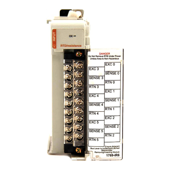
Overview Hardware Features The RTD/resistance module contains a removable terminal block (spare part number 1769-RTBN18) providing connections for six 3-wire inputs for any combination of RTD and resistance input devices. Channels are wired as differential inputs. The illustration below shows the hardware features of the module. -
Page 17: General Diagnostic Features
Overview General Diagnostic Features A single diagnostic LED helps you identify the source of problems that may occur during power-up or during normal channel operation. The LED indicates both status and power. See Chapter 5, Diagnostics and Troubleshooting, for details on power-up and channel diagnostics. System Overview The modules communicate to the local controller or communication adapter through the 1769 bus interface. -
Page 18: Module Operation
Overview Module Operation As shown in the block diagram below, each input channel of the module consists of an RTD/resistance connection that accepts excitation current; a sense connection that detects lead wire resistance; and a return connection. The signals are multiplexed to an A/D converter that reads the RTD or resistance value and the lead wire resistance. -
Page 19: Quick Start For Experienced Users
This chapter can help you to get started using the 1769-IR6 module. We base the procedures here on the assumption that you have an understanding of Allen-Bradley controllers. You should understand electronic process control and be able to interpret the ladder logic instructions required to generate the electronic signals that control your application. - Page 20 Quick Start for Experienced Users Step 1: Ensure that your 1769 system power supply Reference has sufficient current output to support your system configuration. Chapter 3 (Installation and Wiring) The modules maximum current draw is shown below. 5V dc 24V dc 100 mA 45 mA The module cannot be located more than 8 modules...
- Page 21 Quick Start for Experienced Users 3. Move the module back along the tongue-and-groove slots until the bus connectors (2) line up with each other. 4. Push the bus lever back slightly to clear the positioning tab (3). Use your fingers or a small screwdriver. 5.
- Page 22 • If noise persists for a device, try grounding the opposite end of the cable. (You can only ground one end at a time.) • Refer to Industrial Automation Wiring and Grounding Guidelines, Allen-Bradley publication 1770-4.1, for additional information. RTD Wiring Considerations • The module requires three wires to compensate for lead resistance error.
- Page 23 Quick Start for Experienced Users Terminal Connections 1769-IR6 EXC 0 EXC 3 SENSE 0 SENSE 3 RTN 0 RTN 3 EXC 1 EXC 4 SENSE 1 SENSE 4 RTN 1 RTN 4 EXC 2 EXC 5 SENSE 2 SENSE 5 RTN 2 RTN 5 For examples of RTD and resistance device wiring see Wiring RTDs on...
- Page 24 Quick Start for Experienced Users Step 5: Go through the startup procedure. Reference Chapter 5 (Module Diagnostics and Troubleshooting) 1. Apply power to the system. 2. Download your program, which contains the module configuration settings, to the controller. 3. Put the controller into Run mode. During a normal start-up, the module status LED turns on.
-
Page 25: Installation And Wiring
EN 61131-2 Programmable Controllers, Part 2 – Equipment Requirements and Tests. For specific information required by EN61131-2, see the appropriate sections in this publication, as well as the following Allen-Bradley publications: • Industrial Automation, Wiring and Grounding Guidelines for Noise Immunity, publication 1770-4.1... -
Page 26: Power Requirements
Installation and Wiring Power Requirements The module receives +5V dc and 24V dc power from the system power supply through the CompactBus interface. The maximum current drawn by the module is shown in the table below. 5V dc 24V dc 100 mA 45 mA When you configure your system, ensure that the total... -
Page 27: Prevent Electrostatic Discharge
Installation and Wiring Prevent Electrostatic Discharge Electrostatic discharge can damage integrated circuits or ATTENTION semiconductors if you touch analog I/O module bus connector pins or the terminal block on the input module. Follow these guidelines when you handle the module: •... -
Page 28: System Assembly
Installation and Wiring Group your modules to minimize adverse effects from radiated electrical noise and heat. Consider the following conditions when selecting a location for the module. Position the module: • away from sources of electrical noise such as hard-contact switches, relays, and AC motor drives •... - Page 29 Installation and Wiring The following procedure shows you how to assemble the Compact I/O system. 1. Disconnect power. 2. Check that the bus lever of the module to be installed is in the unlocked (fully right) position. 3. Use the upper and lower tongue-and-groove slots (1) to secure the modules together (or to a controller).
-
Page 30: Mounting
Installation and Wiring Mounting ATTENTION During panel or DIN rail mounting of all devices, be sure that all debris (metal chips, wire strands, etc.) is kept from falling into the module. Debris that falls into the module could cause damage at power up. Minimum Spacing Maintain spacing from enclosure walls, wireways, adjacent equipment, etc. -
Page 31: Din Rail Mounting
Installation and Wiring Panel Mounting Procedure Using Modules as a Template The following procedure allows you to use the assembled modules as a template for drilling holes in the panel. If you have sophisticated panel mounting equipment, you can use the dimensional template provided on page 3-6. -
Page 32: Field Wiring Connections
Installation and Wiring 4. On the right-side adjacent module, move its bus lever to the right (unlock) to disconnect it from the module to be removed. 5. Gently slide the disconnected module forward. If you feel excessive resistance, check that the module has been disconnected from the bus, and that both mounting screws have been removed (or DIN latches opened). -
Page 33: Rtd Wiring Considerations
(You can only ground one end at a time.) • Refer to Industrial Automation Wiring and Grounding Guidelines, Allen-Bradley publication 1770-4.1, for additional information. RTD Wiring Considerations Since the operating principle of the RTD module is based on the measurement of resistance, take special care when selecting your input cable. -
Page 34: Terminal Door Label
3-10 Installation and Wiring When using a 3-wire configuration, the module compensates for resistance error due to lead wire length. For example, in a 3-wire configuration, the module reads the resistance due to the length of one of the wires and assumes that the resistance of the other wire is equal. If the resistances of the individual lead wires are much different, an error may exist. -
Page 35: Wiring The Finger-Safe Terminal Block
Installation and Wiring 3-11 wiring the upper retaining screw finger-safe terminal block lower retaining screw Wiring the Finger-Safe Terminal Block When wiring the terminal block, keep the finger-safe cover in place. If you need to remove the finger-safe cover, insert a NOTE screwdriver into one of the square, wiring holes and gently pry the cover off. -
Page 36: Wiring The Modules
3-12 Installation and Wiring Wire Size and Terminal Screw Torque Each terminal accepts up to two wires with the following restrictions: Wire Type Wire Size Terminal Screw Retaining Screw Torque Torque Solid Cu-90°C (194°F) #14 to #22 AWG 0.68 Nm (6 in-lbs) 0.46 Nm (4.1 in-lbs) Stranded Cu-90°C (194°F) #16 to #22 AWG... -
Page 37: Wiring Rtds
Installation and Wiring 3-13 ATTENTION Be careful when stripping wires. Wire fragments that fall into a module could cause damage at power up. 3. At the module end of the cable, twist the drain wire and foil shield together, bend them away from the cable, and apply shrink wrap. Then earth ground via a panel or DIN rail mounting screw at the end of the module. -
Page 38: Wiring Resistance Devices (Potentiometers)
3-14 Installation and Wiring 2-Wire RTD Configuration Cable Shield (to Ground) Add Jumper RTD EXC RTD EXC EXC 3 Return Return SENSE 3 RTN 3 EXC 4 Belden 9501 Shielded Cable 3-Wire RTD Configuration Cable Shield (to Ground) RTD EXC RTD EXC EXC 3 Sense... - Page 39 Installation and Wiring 3-15 2-Wire Potentiometer Interconnection Potentiometer Add Jumper Cable Shield (to Ground) RTD EXC EXC 3 SENSE 3 Return RTN 3 Belden 9501 Shielded Cable Add Jumper Cable Shield (to Ground) Potentiometer RTD EXC EXC 3 SENSE 3 Return RTN 3 Belden 9501 Shielded Cable...
- Page 40 3-16 Installation and Wiring Publication 1769-UM005A-EN-P...
-
Page 41: Module Data, Status, And Channel Configuration
Chapter Module Data, Status, and Channel Configuration After installation of the 1769-IR6 RTD/resistance input module, you must configure it for operation, usually using the programming software compatible with the controller (for example, RSLogix 500™ or RSLogix 5000™). Once configuration is complete and reflected in ladder logic, you will need to get the module up and running and then verify its operation. -
Page 42: Input Image
Module Data, Status, and Channel Configuration Input Image The input image file represents data words and status words. Input words 0 through 5 hold the input data that represents the value of the analog inputs for channels 0 through 5. These data words are valid only when the channel is enabled and there are no errors. -
Page 43: Input Data Values
Module Data, Status, and Channel Configuration Input Data Values Data words 0 through 5 correspond to channels 0 through 5 and contain the converted analog input data from the input device. Status bits for a particular channel reflect the configuration NOTE settings for that channel. -
Page 44: Open-Circuit Flag Bits (Oc0 To Oc5)
Module Data, Status, and Channel Configuration Open-Circuit Flag Bits (OC0 to OC5) Bits OC0 through OC5 of word 6 contain open-circuit error information for channels 0 through 5, respectively. For an RTD input, the bits indicate either an open-circuit or short-circuit condition when set (1). For a resistance input, the bits indicate an open-circuit when set (1). -
Page 45: Configuring Channels
Module Data, Status, and Channel Configuration Configuring Channels After module installation, you must configure operation details, such as RTD type, temperature units, etc., for each channel. Channel configuration data for the module is stored in the controller configuration file, which is both readable and writable. Configuration Data File The configuration data file is shown below. -
Page 46: Channel Configuration
Module Data, Status, and Channel Configuration The following table shows the basic arrangement of the configuration data file. Table 4.3 Configuration Data File Word/ 14 13 12 11 Enable/ Data Format Input/Sensor Type Temperature Open/Broken Cyclic Lead Excitation Filter Frequency Disable Channel 0 Channel 0... - Page 47 Module Data, Status, and Channel Configuration Table 4.4 Channel Configuration Bit Definitions To Select Make these bit settings 10 Hz 60 Hz 50 Hz Filter Frequency 250Hz 500 Hz 1 kHz 1.0 mA Excitation Current 0.5 mA Enable Cyclic Lead Compensation Disable Upscale...
-
Page 48: Enabling Or Disabling A Channel (Bit 15)
Module Data, Status, and Channel Configuration Enabling or Disabling a Channel (Bit 15) Bit 15 enables or disables each of the six channels individually. The module only scans those channels that are enabled. Enabling a channel forces it to be recalibrated before it measures input data. Turning a channel off results in the channel data being set to zero. - Page 49 Module Data, Status, and Channel Configuration Table 4.5 Data Formats for RTD Temperature Ranges for 0.5 and 1.0 mA Excitation Current Data Format RTD Input Type Engineering Units x1 Engineering Units x10 Proportional Scaled-for-PID Counts 0.1°C 0.1°F 1.0°C 1.0°F 100Ω Platinum 385 -2000 to +8500 -3280 to +15620 -200 to +850...
- Page 50 4-10 Module Data, Status, and Channel Configuration Linear Relationship Between Temperature and Proportional Counts Counts + 32,767 ±200 ˚C °C 850 ˚C -32,768 The value +32767 corresponds to the highest value for the device. For example, if a 100 Ω platinum 385 RTD is selected, the lowest temperature of -200 °...
- Page 51 Module Data, Status, and Channel Configuration 4-11 Engineering Units x1 to Scaled-for-PID EXAMPLE • input type = 200Ω Platinum RTD • α = 0.00385°C • range = -200 to +850°C = -200°C = +850°C HIGH • desired channel temperature = 344°C (engineering units) Scaled-for-PID Equivalent = 16383 x [(desired ch.
- Page 52 4-12 Module Data, Status, and Channel Configuration Engineering Units x 1 Data Format If you select engineering units x 1 as the data format for an RTD input, the module scales input data to the actual temperature values for the selected RTD type per RTD standard.
-
Page 53: Selecting Input/Sensor Type (Bits 8 To 11)
The amount over and under user range (full-scale range -410 to +16793) is also included in the signed integer provided to the controller. Allen-Bradley controllers, such as the MicroLogix 1500, use this range in their PID equations. See Determining Effective Resolution and Range on page 4-19. -
Page 54: Selecting Temperature Units/Mode (Bit 7)
4-14 Module Data, Status, and Channel Configuration Selecting Temperature Units/Mode (Bit 7) The module supports two different linearized, scaled temperature ranges for RTDs, degrees Celsius (°C) and degrees Fahrenheit (°F). You can select the type that is appropriate for your application by setting bit 7 in the channel configuration word. -
Page 55: Selecting Excitation Current (Bit 3)
Module Data, Status, and Channel Configuration 4-15 change from Program-to-Run or if any online configuration change is made to a channel. Selecting Excitation Current (Bit 3) The module is capable of exciting each individual RTD/resistance device with either 0.5 mA or 1.0 mA of current. Setting bit 3 to 0 provides 1.0 mA, while a setting of 1 provides 0.5 mA. - Page 56 4-16 Module Data, Status, and Channel Configuration Effects of Filter Frequency on Noise Rejection The filter frequency that you choose for a channel determines the amount of noise rejection for the inputs. A smaller filter frequency (e.g. 10Hz) provides the best noise rejection and increases effective resolution, but also increases channel update time.
- Page 57 Module Data, Status, and Channel Configuration 4-17 Channel Cutoff Frequency The channel cutoff frequency (-3 dB) is the point on the input channel frequency response curve where frequency components of the input signal are passed with 3 dB of attenuation. The following table shows cutoff frequencies for the supported filters.
- Page 58 4-18 Module Data, Status, and Channel Configuration Frequency Response Graphs 10 Hz Input Filter Frequency 50 Hz Input Filter Frequency –3 dB –3 dB –20 –20 –40 –40 –60 –60 –80 –80 -100 -100 -120 -120 -140 -140 -160 -160 -180 -180 - 200...
-
Page 59: Selecting Enable/Disable Cyclic Autocalibration (Word 6, Bit 0)
Module Data, Status, and Channel Configuration 4-19 Selecting Enable/Disable Cyclic Autocalibration (Word 6, Bit 0) Configuration word 6, bit 0 allows you to configure the module to perform an autocalibration cycle of all enabled channels once every 5 minutes. Cyclic calibration functions to reduce offset and gain drift errors due to temperature changes within the module. - Page 60 4-20 Module Data, Status, and Channel Configuration Table 4.9 Effective Resolution and Range for 10 Hz Filter Frequency Raw/Proportional Data Engineering Units x 1 Engineering Units x 10 Scaled for PID Over Full Percent of Full Scale Over Full Input Range Over Full Range Over Full Range Range...
- Page 61 Module Data, Status, and Channel Configuration 4-21 Table 4.10 Effective Resolution and Range for 50-60 Hz Filter Frequency Input Raw/Proportional Data Engineering Units x 1 Engineering Units x 10 Scaled for PID Over Full Percent of Full Scale Type Over Full Range Over Full Input Range Over Full Range Range...
- Page 62 4-22 Module Data, Status, and Channel Configuration Table 4.11 Effective Resolution and Range for 250 Hz Filter Frequency Input Raw/Proportional Data Engineering Units x 1 Engineering Units x Scaled for PID Over Full Percent of Full Scale Type Over Full Input Range Over Full Range 10 Over Full Range Range...
- Page 63 Module Data, Status, and Channel Configuration 4-23 Table 4.12 Effective Resolution and Range for 500 Hz Filter Frequency Raw/Proportional Data Engineering Units x 1 Engineering Units x Scaled for PID Over Full Percent of Full Scale Over Full Input Range Over Full Range 10 Over Full Range Range...
- Page 64 4-24 Module Data, Status, and Channel Configuration Table 4.13 Effective Resolution and Range for 1 kHz Filter Frequency Input Raw/Proportional Data Engineering Units x 1 Engineering Units x 10 Scaled for PID Over Full Percent of Full Scale Type Over Full Input Range Over Full Range Over Full Range Range...
- Page 65 Module Data, Status, and Channel Configuration 4-25 The table below identifies the number of significant bits used to represent the input data for each available filter frequency. The number of significant bits is defined as the number of bits that will have little or no jitter due to noise, and is used in defining the effective resolution.
-
Page 66: Determining Module Update Time
4-26 Module Data, Status, and Channel Configuration Determining Module The module update time is defined as the time required for the module to sample and convert the input signals of all enabled input channels and Update Time provide the resulting data values to the processor. The module sequentially samples the channels in a continuous loop as shown below. -
Page 67: Effects Of Autocalibration On Module Update Time
Module Data, Status, and Channel Configuration 4-27 Effects of Autocalibration on Module Update Time The module’s autocalibration feature allows it to correct for accuracy errors caused by component temperature drift over the module operating temperature range (0 to 60°C). Autocalibration occurs automatically on a system mode change from Program-to-Run for all configured channels. -
Page 68: Enabled
4-28 Module Data, Status, and Channel Configuration Table 4.17 Input Type and Class Input Class Input Type Using 0.5 mA Source Using 1.0 mA Source 100Ω Pt 385 200Ω Pt 385 500Ω Pt 385 1000Ω Pt 385 Cannot use this source 100Ω... - Page 69 Module Data, Status, and Channel Configuration 4-29 Two Channels Enabled Using the Same Input Class with Cyclic Calibration Enabled EXAMPLE Channel 0 Input: 100Ω Platinum 385, 1.0 mA source (Class 2) with 60 Hz Filter Channel 1 Input: 1000Ω resistance, 0.5 mA source (Class 2) with 60 Hz Filter From Table 4.15, Channel Update Time vs.
-
Page 70: Effects Of Cyclic Lead Wire Compensation On Module Update Time
4-30 Module Data, Status, and Channel Configuration Effects of Cyclic Lead Wire Compensation on Module Update Time The 1769-IR6 module provides the option to enable lead wire compensation for each channel. This feature improves measurement accuracy for 3- and 4-wire RTDs by compensating for the resistance of the RTD lead wire. -
Page 71: Calculating Module Update Time With Cyclic Lead Wire Compensation Enabled
Module Data, Status, and Channel Configuration 4-31 Calculating Module Update Time with Cyclic Lead Wire Compensation Enabled The following example illustrates how to determine module update time with cyclic lead wire compensation enabled. Two Channels Configured with Cyclic Lead Wire Compensation Enabled EXAMPLE Channel 0 Input: 100Ω... -
Page 72: Impact Of Autocalibration And Lead Wire Compensation On Module Startup
4-32 Module Data, Status, and Channel Configuration Impact of Autocalibration and Lead Wire Compensation on Module Startup Regardless of the selection of the Enable/Disable Cyclic Calibration and Enable/Disable Cyclic Lead Calibration functions, an cycle of both of these functions occurs automatically on a mode change from Program-to-Run and on subsequent module startups/initialization for all configured channels. -
Page 73: Effects Of Autocalibration On Accuracy
Module Data, Status, and Channel Configuration 4-33 Effects of The module performs autocalibration to correct for drift errors over temperature. Autocalibration occurs immediately following configuration Autocalibration on of a previously unselected channel, during power cycle of enable Accuracy channels and every 5 minutes if so configured. The table below shows module accuracy with and without calibration. - Page 74 4-34 Module Data, Status, and Channel Configuration Publication 1769-UM005A-EN-P...
-
Page 75: Diagnostics And Troubleshooting
Chapter Diagnostics and Troubleshooting This chapter describes module troubleshooting, containing information • safety considerations when troubleshooting • module vs. channel operation • the module’s diagnostic features • critical vs. non-critical errors • module condition data • contacting Rockwell Automation for assistance Safety Considerations Safety considerations are an important element of proper troubleshooting procedures. -
Page 76: Stand Clear Of The Equipment
Diagnostics and Troubleshooting Stand Clear of the Equipment When troubleshooting any system problem, have all personnel remain clear of the equipment. The problem could be intermittent, and sudden unexpected machine motion could occur. Have someone ready to operate an emergency stop switch in case it becomes necessary to shut off power. Program Alteration There are several possible causes of alteration to the user program, including extreme environmental conditions, Electromagnetic Interference... -
Page 77: Power-Up Diagnostics
Diagnostics and Troubleshooting Power-up Diagnostics At module power-up, a series of internal diagnostic tests are performed. These diagnostic tests must be successfully completed or the module status LED remains off and a module error results and is reported to the controller. -
Page 78: Open-Wire Or Short-Circuit Detection
Diagnostics and Troubleshooting Open-Wire or Short-Circuit Detection The module performs an open-circuit or short-circuit input test on all enabled channels on each scan. Whenever an open-circuit or short-circuit condition occurs, the broken input bit for that channel is set in input data word 6. -
Page 79: Module Error Field
Diagnostics and Troubleshooting Module Error Field The purpose of the module error field is to classify module errors into three distinct groups, as described in the table below. The type of error determines what kind of information exists in the extended error information field. -
Page 80: Error Codes
Diagnostics and Troubleshooting Error Codes The table below explains the extended error code. Table 5.3 Extended Error Codes Error Type Module Extended Error Error Description Error Information Equivalent Code Code Binary Binary No Error X000 0 0000 0000 No Error General Common X200 0 0000 0000... - Page 81 Diagnostics and Troubleshooting Table 5.3 Extended Error Codes Error Type Module Extended Error Error Description Error Information Equivalent Code Code Binary Binary X400 0 0000 0000 General configuration error; no additional information X401 0 0000 0001 Invalid input filter selected (channel 0) X402 0 0000 0010 Invalid input filter selected (channel 1)
-
Page 82: Module Inhibit Function
Diagnostics and Troubleshooting Module Inhibit Function Some controllers support the module inhibit function. See your controller manual for details. Whenever the 1769-IR6 module is inhibited, the module continues to provide information about changes at its inputs to the 1769 CompactBus master (for example, a CompactLogix controller). -
Page 83: Specifications
Appendix Specifications General Specifications Specification Value Dimensions 118 mm (height) x 87 mm (depth) x 35 mm (width) height including mounting tabs is 138 mm 4.65 in. (height) x 3.43 in (depth) x 1.38 in (width) height including mounting tabs is 5.43 in. Approximate Shipping Weight 276g (0.61 lbs.) (with carton) -
Page 84: Input Specifications
Specifications Input Specifications Specification 1769-IR6 • 100Ω Platinum 385 Input Types • 200Ω Platinum 385 • 500Ω Platinum 385 • 1000Ω Platinum 385 • 100Ω Platinum 3916 • 200Ω Platinum 3916 • 500Ω Platinum 3916 • 1000Ω Platinum 3916 • 10Ω Copper 426 •... - Page 85 Specifications Specification 1769-IR6 Accuracy Drift at 0 to 60° C (+32 to ±0.026°C/°C (0.026°F/°F) for Pt 385 ±0.007Ω/°C (0.012Ω/°F) for 150Ω range +140°F) ±0.023°C/°C (0.023°F/°F) for Pt 3916 ±0.023Ω/°C (0.041Ω/°F) for 500Ω range ±0.012°C/°C (0.012°F/°F) for Ni ±0.043Ω/°C (0.077Ω/°F) for 1000Ω range ±0.015°C/°C (0.015°F/°F) for NiFe ±0.072Ω/°C (0.130Ω/°F) for 3000Ω...
-
Page 86: Cable Specifications
Specifications Cable Specifications Description Belden #9501 Belden #9533 Belden #83503 When used? For 2-wire RTDs and For 3-wire RTDs and For 3-wire RTDs and potentiometers. potentiometers. potentiometers. Short runs less than Long runs greater than 100 feet and normal 100 feet or high humidity levels. -
Page 87: Module Addressing And Programming With Micrologix 1500 And Rslogix
Appendix Module Addressing and Programming with MicroLogix 1500 and RSLogix 500 Module Addressing The module uses eight input words for data and status bits (input image), and seven configuration words. Address Memory Map Word 0 I:e.0 Channel 0 Data Word Word 1 I:e.1 Channel 1 Data Word... -
Page 88: 1769-Ir6 Configuration File
Module Addressing and Programming with MicroLogix 1500 and RSLogix 500 Slot Number The end cap does not use a slot address. NOTE 1769-IR6 Configuration File The configuration file contains information you use to define the way a specific channel functions. The configuration file is explained in more detail in Configuring Channels on page 4-5. - Page 89 Module Addressing and Programming with MicroLogix 1500 and RSLogix 500 Start RSLogix and create a MicroLogix 1500 application. The following screen appears: While offline, double-click on the IO Configuration icon under the controller folder and the following IO Configuration screen appears. This screen allows you to manually enter expansion modules into expansion slots, or to automatically read the configuration of the controller.
- Page 90 Module Addressing and Programming with MicroLogix 1500 and RSLogix 500 A communications dialog appears, identifying the current communications configuration so that you can verify the target controller. If the communication settings are correct, click on Read IO Config. The actual I/O configuration will be displayed. The 1769-IR6 module is installed in slot 1.
- Page 91 Module Addressing and Programming with MicroLogix 1500 and RSLogix 500 Configuration options for channels 0 to 2 are located on a separate tab from channels 3 to 5, as shown below. To enable a channel, click its Enable box so that a check mark appears in it. For optimum module performance, disable any channel that is not hardwired to a real input.
- Page 92 Module Addressing and Programming with MicroLogix 1500 and RSLogix 500 Generic Extra Data Configuration This tab redisplays the configuration information entered on the Analog Input Configuration screen in a raw data format. You have the option of entering the configuration using this tab instead of the module Configuration tab.
-
Page 93: Configuring The 1769-Ir6 Rtd
Appendix Configuring the 1769-IR6 RTD Module with the Generic Profile for CompactLogix Controllers using RSLogix5000 The following is used only when your 1769-IR6 RTD Input module profile is not available in RSLogix 5000 Programming Software. The initial release of the CompactLogix5320 controller includes the Generic I/O Profile, with individual I/O module profiles to follow. - Page 94 Configuring the 1769-IR6 RTD Module with the Generic Profile for CompactLogix Controllers using RSLogix5000 The last entry in the Controller Organizer on the left of the screen shown above is a line labeled “[0] CompactBus Local”. Right click on this line, select “New Module”...
- Page 95 Configuring the 1769-IR6 RTD Module with the Generic Profile for CompactLogix Controllers using RSLogix5000 This screen narrows your search for I/O modules to configure into your system. With the initial release of the CompactLogix5320 controller, this screen only includes the “Generic 1769 Module”. Click the OK button and the following default Generic Profile screen appears: This is the default Generic Profile screen.
-
Page 96: Configuring I/O Modules
Configuring the 1769-IR6 RTD Module with the Generic Profile for CompactLogix Controllers using RSLogix5000 Click “Finish” to complete the configuration of your I/O module. Configure each RTD Input module in this manner. The CompactLogix5320 controller supports a maximum of eight I/O modules. The valid slot numbers to select when configuring I/O modules are 1 through 8. -
Page 97: Configuring A 1769-Ir6 Rtd Input Module
Configuring the 1769-IR6 RTD Module with the Generic Profile for CompactLogix Controllers using RSLogix5000 Tag addresses are automatically created for configured I/O modules. All local I/O addresses are preceded by the word Local. These addresses have the following format: • Input Data: Local:s:I •... - Page 98 Configuring the 1769-IR6 RTD Module with the Generic Profile for CompactLogix Controllers using RSLogix5000 The tag addresses for these 8 words are Local:1:C.Data[0] through Local:1:C.Data[7]. Only the first 6 words of the configuration file apply. The last 2 words must exist but should each contain a value of 0 decimal. The 6 configuration words, 0 through 5 apply to IR6 channels 0 through 5 respectively.
- Page 99 Appendix Configuring Your 1769-IR6 RTD/resistance Input Module in a Remote DeviceNet System with a 1769-ADN DeviceNet Adapter This application example assumes your 1769-IR6 RTD/resistance input module is in a remote DeviceNet system controlled by a 1769-ADN DeviceNet adapter. RSNetworx for DeviceNet is not only used to configure your DeviceNet network, but is also used to configure individual I/O modules in remote DeviceNet adapter systems.
- Page 100 Configuring Your 1769-IR6 RTD/resistance Input Module in a Remote DeviceNet System with a 1769-ADN DeviceNet Adapter Start RSNetworx for DeviceNet. The following screen appears: In the left column under Category, click on the “+” sign next to Communication Adapters. In the list of products under Communication Adapters is the 1769-ADN/A.
- Page 101 Configuring Your 1769-IR6 RTD/resistance Input Module in a Remote DeviceNet System with a 1769-ADN DeviceNet Adapter In order to configure I/O for the adapter, double-click on the adapter that you just placed on the network and the following screen appears: At this point you may modify the adapters DeviceNet node address, if desired.
- Page 102 Configuring Your 1769-IR6 RTD/resistance Input Module in a Remote DeviceNet System with a 1769-ADN DeviceNet Adapter Next, click on the I/O Bank 1 Configuration tab. The following screen appears: Configuring the 1769-IR6 The 1769-ADN appears in slot 0. Your I/O modules, power supplies, end cap and interconnect cables must be entered in the proper order, following the 1769 I/O rules contained in the 1769-ADN user’s manual.
- Page 103 Configuring Your 1769-IR6 RTD/resistance Input Module in a Remote DeviceNet System with a 1769-ADN DeviceNet Adapter By default, the 1769-IR6 module contains eight input words and no output words. Click on the “Data Description…” button. This shows what the eight input words represent, i.e. the first six words are the actual RTD input data, while the following two words contain status, open-circuit bits and over- and under-range bits for the six channels.
- Page 104 Configuring Your 1769-IR6 RTD/resistance Input Module in a Remote DeviceNet System with a 1769-ADN DeviceNet Adapter temperature data in degrees F. For the thermocouple used, the default Excitation Current of 1.0 mA is used. Temperature Units is ignored for the resistance device inputs for channels 4 and 5.
-
Page 105: Positive Decimal Values
Appendix Two’s Complement Binary Numbers The processor memory stores 16-bit binary numbers. Two’s complement binary is used when performing mathematical calculations internal to the processor. Analog input values from the analog modules are returned to the processor in 16-bit two’s complement binary format. For positive numbers, the binary notation and two’s complement binary notation are identical. -
Page 106: Negative Decimal Values
Two’s Complement Binary Numbers Negative Decimal In two’s complement notation, the far left position is always 1 for negative values. The equivalent decimal value of the binary number is obtained by Values subtracting the value of the far left position, 32768, from the sum of the values of the other positions. - Page 107 Glossary The following terms and abbreviations are used throughout this manual. For definitions of terms not listed here refer to Allen-Bradley’s Industrial Automation Glossary, Publication AG-7.1. A/D Converter– Refers to the analog to digital converter inherent to the module. The converter produces a digital value whose magnitude is proportional to the magnitude of an analog input signal.
- Page 108 data word – A 16-bit integer that represents the value of the input channel. The channel data word is valid only when the channel is enabled and there are no channel errors. When the channel is disabled the channel data word is cleared (0). dB –...
- Page 109 linearity error – Any deviation of the converted input or actual output from a straight line of values representing the ideal analog input. An analog input is composed of a series of input values corresponding to digital codes. For an ideal analog input, the values lie in a straight line spaced by inputs corresponding to 1 LSB.
- Page 110 resolution – The smallest detectable change in a measurement, typically expressed in engineering units (e.g. 1°C) or as a number of bits. For example a 12-bit system has 4096 possible output states. It can therefore measure 1 part in 4096. RTD –...
- Page 111 Index channel update time 4-17 definition CMRR. See common mode rejection ratio definition common mode 4-16 A/D converter voltage 4-16 abbreviations common mode rejection accuracy definition autocalibration 4-33 common mode rejection ratio module 4-33 definition overall common mode voltage resistance device definition addressing common mode voltage range...
- Page 112 Index DIN rail and noise rejection 4-16 latch definition mounting finger-safe terminal block 3-11 door frequency response graphs 4-17 downscale frequency. See filter frequency. 4-14 full-scale definition full-scale range effective resolution definition 1 kHz 4-24 10 Hz 4-20 250 Hz 4-22 500 Hz gain drift...
- Page 113 Index power-up diagnostics power-up sequence microprocessor program alteration module error field programming software module inhibit function module scan time definition module status range data not valid 1 kHz 4-24 general status bits 10 Hz 4-20 open-circuit bits 250 Hz 4-22 over-range flag bits 500 Hz 4-23...
- Page 114 Index step response time two’s complement binary numbers definition system operation under-range flag bits update time. See channel update time. temperature drift update time. See module update time. 4-33 temperature units upscale 4-14 4-14 terminal block removing 3-10 retaining screw wire size 3-12 wiring...
- Page 115 AB PLCs...
- Page 116 Publication 1769-UM005A-EN-P - February 2001 © 2001 Rockwell International Corporation. Printed in the U.S.A.
Need help?
Do you have a question about the Compact 1769-IR6 and is the answer not in the manual?
Questions and answers