Table of Contents
Advertisement
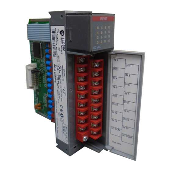
Discrete I/O Modules
(Catalog Number 1746 Series)
Installation Instructions
Input Module Catalog Numbers:
1746-IA4, -IA8, -IA16, -IB8, -IB16, -IC16, -IG16, -IH16, -IM4,
-IM8, -IM16,
-IN16, -ITB16, -ITV16, -IV8, -IV16
Output Module Catalog Numbers:
1746-OA8, -OA16, -OAP12, -OB8, -OB6EI, -OB16, -OB16E,
-OBP8,
-OBP16, -OG16, -OV8, -OV16, -OVP16, -OW4, -OW8, -
OW16, -OX8
Combination Input/Output Module Catalog Numbers:
1746-IO4, -IO8, -IO12, -IO12DC
Publication 1746-IN005A-US-P
Advertisement
Table of Contents

Related Manuals for Allen-Bradley 1746 Series


Summary of Contents for Allen-Bradley 1746 Series
- Page 1 Discrete I/O Modules (Catalog Number 1746 Series) Installation Instructions Input Module Catalog Numbers: 1746-IA4, -IA8, -IA16, -IB8, -IB16, -IC16, -IG16, -IH16, -IM4, -IM8, -IM16, -IN16, -ITB16, -ITV16, -IV8, -IV16 Output Module Catalog Numbers: 1746-OA8, -OA16, -OAP12, -OB8, -OB6EI, -OB16, -OB16E,...
- Page 2 Reproduction of the contents of this copyrighted publication, in whole or in part, without written permission of Allen-Bradley Company, Inc., is prohibited. Throughout these installation instructions we use notes to make you aware of...
-
Page 3: Table Of Contents
Discrete I/O Modules Table of Contents Overview ..........4 Hazardous Location Considerations. - Page 4 Discrete I/O Modules Input/Output Combination Modules ......50 Publication 1746-IN005A-US-P...
-
Page 5: Overview
Discrete I/O Modules Overview In addition to providing the module’s electrical specifications, this document tells you how to: • install the module into a chassis • wire the module’s terminal block • install the Octal Filter Label Hazardous Location Considerations This equipment is suitable for use in Class I, Division 2, Groups A, B, C, D or non-hazardous locations only. -
Page 6: Installation
Discrete I/O Modules Installation ATTENTION: Never install, remove, or wire modules with power applied to chassis. IMPORTANT : The first slot of the chassis is reserved for the processor or the 1747-ASB module. 1. Disconnect power. 2. Align circuit board of module with chassis card guide. -
Page 7: Specifications
Discrete I/O Modules Specifications General I/O Table 1: Specifications for All Discrete Modules Operating Temperature 0°C to 60°C (32°F to 140°F) Storage Temperature -40°C to 85°C (-40°F to 185°F) Operating Humidity 5% to 95% (noncondensing) Noise Immunity NEMA standard ICS 2-230 Displacement 0.015 in peak at 5 to 57 Hz Vibration (Operating) Acceleration 2.5Gs at 57 to 2000 Hz... -
Page 8: Heat Dissipation
Discrete I/O Modules Heat Dissipation The following tables contain values for the heat dissipated by each I/O module. Use them to calculate the total amount of heat dissipated by your SLC 500™ control system. For details on how to calculate total heat dissipation, refer to the SLC 500 Modular Hardware Style Installation and Operation Manual, publication 1747-6.2. - Page 9 Discrete I/O Modules Table 3: Output Module Heat Dissipation Catalog Numbers Watts per Point Minimum Watts Total Watts 1746-OA8 1.000 0.925 9.00 1746-OA16 0.462 1.850 9.30 1746-OAP12 1.000 1.850 10.85 1746-OB6EI 0.440 0.230 2.90 1746-OB8 0.775 0.675 6.90 1746-OB16 0.388 1.400 7.60 1746-OB16E...
-
Page 10: Input Modules - Ac
Discrete I/O Modules Input Modules - ac Table 5: Specifications for Input Modules 1746-IA4, -IA8, and -IA16 Catalog Number 1746- Specification IA16 Voltage Category 100/120V ac Signal Input Number of Inputs Points per Common Operating Voltage 85 to 132V ac at 47 to 63 Hz 5V dc 0.035A 0.050A... - Page 11 Discrete I/O Modules Table 6: Specifications for Input Modules 1746-IM4, -IM8, and -IM16 Catalog Number 1746- Specification IM16 Voltage Category 200/240V ac Signal Input Number of Inputs Points per Common Operating Voltage 170 to 265V ac at 47 to 63 Hz 5V dc 0.035A 0.050A...
-
Page 12: Input Modules - Dc
Discrete I/O Modules Input Modules - dc Table 7: Specifications for Input Modules 1746-IB8, -IB16, -ITB16, and -IC16 Catalog Number 1746- Specification (1)(2) IB16 ITB16 IC16 48V dc Voltage Category 24V dc Signal Input (sinking) Signal Input (sinking) Number of Inputs Points per Common 30 to 60V dc at 55°C Operating Voltage... - Page 13 Discrete I/O Modules Table 8: Specifications for Input Modules 1746-IV8, -IV16, and -ITV16 Catalog Number 1746- Specification IV16 ITV16 Voltage Category 24V dc Signal Input (sourcing) Number of Inputs Points per Common Operating Voltage 10 to 30V dc (sourcing) 5V dc 0.050A 0.085A 0.085A...
- Page 14 Operation Manual, publication 1747-6.2, for recommended wiring procedures for TTL modules. Cable Length - Limit cable length to 15 meters (50 feet) per point for inputs in standard environments. Refer to Allen-Bradley Programmable Controller Wiring and Grounding Guidelines, publication 1770-4.1, for complete information. Publication 1746-IN005A-US-P...
- Page 15 Discrete I/O Modules Table 10:Specifications for Input Module 1746-IN16 Specification 1746-IN16 Voltage Category 24V ac/dc Signal Input Number of Inputs Points per Common 10 to 30V dc (sinking) Operating Voltage 10 to 30V ac 5V dc 0.085A Backplane Current Consumption 24V dc 0.0A on = 15 ms...
- Page 16 Discrete I/O Modules Table 11:Specifications for Input Module 1746-IH16 (1)(2)(3) Specification 1746-IH16 Voltage Category 125V dc Signal Input (sinking Number of Inputs Points per common Range: Max. Points ON Simultaneously: • 90 to 146V dc • 16 at 146V dc and 30°C Operating Voltage •...
-
Page 17: Output Modules - Ac
Discrete I/O Modules Output Modules - ac Table 12:Specifications for Output Modules 1746-OA8, -OA16, and -OAP12 Catalog Number 1746- Specification (1)(2)(3) OAP12 OA16 Voltage Category 120/240V ac Signal Input Number of Outputs Points per Common Operating Voltage 85 to 265V ac at 47 to 63 Hz 5V dc 0.185A 0.370A... - Page 18 Discrete I/O Modules (7) Recommended surge suppression: For triac outputs when switching 120V ac inductive loads, use Harris Metal-Oxide Varistor, model number V220MA2A. Refer to the SLC 500 Modular Hardware Style Installation and Operation Manual , publication 1747-6.2, for more information on surge suppression. (8) Repeatability is once every 1s at 30°C.
-
Page 19: Output Modules - Dc
Discrete I/O Modules Output Modules - dc Table 13:Specifications for Output Modules 1746-OB8, -OB16, and -OB16E Catalog Number 1746- Specification (1)(2) OB16 OB16E Number of Outputs Points per Common Voltage Category 24V dc Signal Output 10 to 30 Operating Voltage (V dc) 10 to 50 (source) (source) 5V dc... - Page 20 Discrete I/O Modules (5) Recommended surge suppression: For transistor outputs when switching 24V dc inductive loads, use a 1N4004 diode reverse-wired across the load. Refer to the SLC 500 Modular Hardware Style Installation and Operation Manual , publication 1747-6.2, for more information on surge suppression.
- Page 21 Discrete I/O Modules Table 14:Specifications for Output Modules 1746-OB6EI, -OBP8, and -OBP16 Catalog Number 1746- Specification (1)(2)(4) OBP16 (1)(2) (1)(2)(3) OB6EI OBP8 Number of Outputs Individually Points per Common Isolated Voltage Category 24V dc Signal Output 10 to 30 Operating Voltage (V dc) 20.4 to 26.4 (source) (source) 5V dc...
- Page 22 Discrete I/O Modules (6) Fast turn-off modules (1746-OB6EI, -OBP8 Series B and later, -OB16E Series B and later, -OBP16, and -OVP16) provide fast OFF delay for inductive loads. Comparative OFF delay times for 1746-OB8/-OV8 and fast turn-off modules; when switching Bulletin 100-B110 (24W sealed) contactor, are: 1746-OB8/-OV8 OFF delay = 152 ms;...
- Page 23 Discrete I/O Modules Table 15:Specifications for Output Modules 1746-OV8, -OV16, and -OVP16 Catalog Number 1746- Specification (1)(2)(3) OVP16 OV16 Number of Outputs Points per Common Voltage Category 24V dc Signal Output 20.4 to 26.4 Operating Voltage (V dc) 10 to 50 (sink) (sink) Backplane 5V dc...
- Page 24 Discrete I/O Modules (6) To limit the effects of leakage current through solid state outputs, a loading resistor can be connected in parallel with your load. For transistor outputs, 24V dc operation, use a 5.6K Ω, 1/2W resistor. (7) Recommended surge suppression: For transistor outputs when switching 24V dc inductive loads, use a 1N4004 diode reverse-wired across the load (also see footnote 9).
- Page 25 Operation Manual, publication 1747-6.2, for recommended wiring procedures for TTL modules. Cable Length - Limit cable length to 3 meters (10 feet) per point for outputs in standard environments. Refer to Allen-Bradley Programmable Controller Wiring and Grounding Guidelines, publication 1770-4.1, for complete information. Publication 1746-IN005A-US-P...
-
Page 26: Relay Contact Output Modules
Discrete I/O Modules Relay Contact Output Modules Table 17:Specifications for Output Modules 1746-OW4, -OW8, -OW16, and - Catalog Number 1746- Specification (1)(2) (1)(2) OW16 Number of Outputs Individually Points per Common Isolated Voltage Category ac/dc Relay 5V dc 5 to 125 Operating Voltage 5 to 265... -
Page 27: Relay Contact Ratings
Discrete I/O Modules Relay Contact Ratings Table 18:Relay Contact Rating Table for Output Modules 1746-OW4, -OW8, and -OW16 Amperes Volt-Amperes Amperes Voltages: Continuous Make Break Make Break Maximum Volts (ac) 1800 0.75 0.22 Maximum Volts (dc) Table 19:Relay Contact Rating Table for Output Module 1746-OX8 Amperes Amperes Volt-Amperes... -
Page 28: Input/Output Combination Modules
Discrete I/O Modules Input/Output Combination Modules Table 20:Specifications for Combination Modules 1746-IO4, -IO8, -IO12, and -IO12DC Catalog Number 1746- Specification (1)(3) (3)(5)(6) IO12 IO12DC (1)(2) (1)(2) 2 inputs 4 inputs 6 inputs 6 inputs Points per Module 2 outputs 4 outputs 6 outputs 6 outputs Points per Common... - Page 29 Discrete I/O Modules Combination I/O modules (Catalog Numbers 1746-IO4, 1746-IO8, 1746-IO12 and Note: 1746-IO12DC: For the first several seconds of any powerup or when power is applied to a rack that is not under processor control, the output LEDs of the combination IO modules in the rack will be illuminated.
-
Page 30: Octal Label Kit Installation (For Plc Processors Only)
I/O modules. The octal label kit is included with the I/O modules and can also be obtained through your Allen-Bradley distributor. ATTENTION: Do not touch or remove the terminal block when the SLC 500 system is powered. -
Page 31: Removable Terminal Blocks
Discrete I/O Modules Removable Terminal Blocks Colored terminal blocks are removable by loosening the upper and lower retaining screws. Black terminal blocks are not removable. Figure 1:Installing Octal Labels Octal Filter Label Module Color Bar Upper Retaining Screw Maximum Beveled Edge OCTAL Torque = 0.6 Nm (5.3 in-lbs) Removable... -
Page 32: Fuse Protection And Blown Fuse Diagnostics
Discrete I/O Modules Fuse Protection and Blown Fuse Diagnostics This section describes fusing characteristics for the following modules: • Catalog 1746-OBP16 • Catalog 1746-OVP16 • Catalog 1746-OAP12 Fuse Protection (1746-OBP16 and 1746-OVP16) The fuse on the 1746-OBP16 and 1746-OVP16 modules (shown on page 33) has been designed to provide short-circuit protection for wiring only (16 AWG or larger) to external loads. - Page 33 Discrete I/O Modules Figure 2:Location of Jumpers and Fuses for 1746-OBP16 and -OVP16 Location for 1746-OBP16 Fuse (F1) JP 1 Jumper for processor Left Side View notification (JP1) Location for 1746-OVP16 Fuse (F1) WHEN FUSE OPENS OUTPUT PROCESSOR CONTINUES Blown Fuse LED PROCESSOR FAULTS REPLACEMENT FUSE:...
- Page 34 Discrete I/O Modules Figure 3:Location of Jumpers and Fuses for 1746-OAP12 Left Side View Jumper for processor notification (JP1) WHEN FUSE OPENS OUTPUT PROCESSOR CONTINUES Blown Fuse LED PROCESSOR FAULTS REPLACEMENT FUSE: SAN-O HQ 6.3A A-B CAT. NO. 1746-F9 Jumper Settings and Fuse Replacement Information Front View...
-
Page 35: Processor Operation In Case Of Blown Fuse - Processor Continues
Discrete I/O Modules Processor Operation in Case of Blown Fuse - Processor Continues The factory set position for JP1 is shown in Figure 4. For this JP1 configuration, the processor operation will continue if the module fuse blows. Figure 4:JP1 Factory Set Position (No Processor Notification) JP1 is in Factory Set position. - Page 36 Discrete I/O Modules Figure 5:JP1 in Processor Fault Notification Position 1746-OBP16 and - JP1 is in processor Fault Position Processor is notified when fuse is blown. 1746- IMPORTANT : When using SLC 5/02 and higher processors, a User Fault Routine cannot be used to clear the major fault bit.
- Page 37 Discrete I/O Modules No error. Processor continues with 1746- Non-recoverable error. OBP16/-OVP16 outputs de-energized. 1746- Processor operations stops and OAP12 outputs, on the same common as the all outputs reset to OFF. blown fuse, are de-energized. Publication 1746-IN005A-US-P...
-
Page 38: Recovery From Blown Fuse/Processor Fault/Processor Shutdown
Discrete I/O Modules Recovery From Blown Fuse/Processor Fault/Processor Shutdown Processor operation will stop under the following conditions: • The output module fuse blows due to a short circuit. • JP1 is set to the Processor Faults position (pins 2 and 3 connected). If the above conditions occur, the following procedures should be used for recovery: 1. -
Page 39: Fuse Replacement Procedure
Discrete I/O Modules Fuse Replacement Procedure To replace a blown fuse: ATTENTION: Never install, remove, or wire modules with power applied to chassis. 1. Remove SLC 500 system power and correct the conditions causing the short circuit. 2. Remove the output module from the chassis. 3. -
Page 40: Electronically Protected Modules (1746-Ob6Ei And -Ob16E)
Discrete I/O Modules Electronically Protected Modules (1746-OB6EI and - OB16E) Electronic Protection The electronic protection of the 1746-OB6EI and -OB16E has been designed to provide protection for the modules from short circuit and overload current conditions. The protection is based on a thermal cut-out principle. In the event of a short circuit or overload current condition on an output channel, that channel will limit current within milliseconds after its thermal cut-out temperature has been reached. -
Page 41: Auto Reset Operation
Discrete I/O Modules Auto Reset Operation IMPORTANT : The 1746-OB6EI and -OB16E perform auto-reset under overload conditions. When an output channel overload occurs as described on page 40, that channel will limit current within milliseconds after its thermal cut-out temperature has been reached. While in current limit, the output channel can cool below the thermal cut- out temperature allowing the module to auto-reset and resume control of the output channel as directed by the processor until the... -
Page 42: Wiring Diagrams
Discrete I/O Modules Wiring Diagrams The wiring diagrams in these installation instructions are examples only. It is not necessary to connect an I/O device to each and every I/O module terminal. ® Labeling for SLC/PLC Systems In this document, 16-point I/O module wiring diagrams include both decimal and octal numbers for I/O addressing and wire identification (see figure below). -
Page 43: Input Modules - Ac
Discrete I/O Modules Input Modules - ac Figure 7:Wiring Diagrams (1746-IA4, -IA8, -IA16) 1746-IA8 1746-IA4 100/120V ac 100/120V ac IN 0 USED IN 1 USED IN 2 USED IN 3 USED 100/120V ac IN 0 IN 4 IN 1 IN 5 100/120V ac IN 2 IN 6... - Page 44 Discrete I/O Modules Figure 8:Wiring Diagrams (1746-IM4, -IM8, -IM16) 1746IM4 1746-IM8 200/240V ac 200/240V ac USED IN 0 IN 1 USED IN 2 USED IN 3 USED 200/240V ac IN 0 IN 4 IN 1 IN 5 200/240V ac IN 2 IN 6 IN 3 IN 7...
-
Page 45: Input Modules - Dc
Discrete I/O Modules Input Modules - dc Figure 9:Wiring Diagram (1746-IN16) 1746-IN16 24V ac/dc SINKING L1 or +DC IN 0 IN 1 IN 2 IN 3 IN 4 IN 5 IN 6 IN 7 V ac/dc IN 8 IN 9 IN 10 IN 11 IN 12... - Page 46 Discrete I/O Modules Figure 11:Wiring Diagram (1746-IV8, -IV16, -ITV16) 1746-IV8 1746-IV16, -ITV16 24V dc SOURCING 24V dc SOURCING ±DC IN 0 ±DC IN 0 IN 1 IN 2 IN 1 IN 3 IN 4 IN 2 IN 5 IN 6 IN 3 24V dc IN 7...
-
Page 47: Output Modules - Ac
Discrete I/O Modules Output Modules - ac Figure 13:Wiring Diagrams (1746-OA8, -OA16) 1746-OA8 100 to 240V ac TRIAC OUTPUT VAC 1 OUT 0 100-240V ac OUT 1 OUT 2 OUT 3 VAC 2 OUT 4 100-240V ac OUT 5 OUT 6 OUT 7 1746-OA16 100 to 240V ac TRIAC OUTPUT... - Page 48 Discrete I/O Modules Figure 14:Wiring Diagram (1746-OAP12) 1746-OAP12 100 to 240V ac HIGH CURRENT TRIAC OUTPUT COMMONS VAC 1 CONNECTED VAC 1 OUT 1 INTERNALLY OUT 0 OUT 3 OUT 2 100-240V ac OUT 5 OUT 4 USED USED OUT 7 OUT 6 OUT 9 100-240V ac...
- Page 49 Discrete I/O Modules Figure 16:Wiring Diagrams (1746-OB8, -OBP8, -OB16, -OB16E, -OBP16) 1746-OB8 1746-OBP8 10 to 50V dc Transistor Output-Sourcing 20.4 to 26.4V dc Transistor Output-Sourcing VDC1 OUT 0 OUT 1 OUT 2 OUT 0 OUT 3 20.4-26.4V dc COM1 OUT 1 OUT 2 OUT 3 10-50V dc...
- Page 50 Discrete I/O Modules Figure 17:Wiring Diagrams (1746-OV8, -OV16, -OVP16) 1746-OV8 10 to 50V dc TRANSISTOR OUTPUT SINKING OUT 0 OUT 1 OUT 2 OUT 3 10-50V dc OUT 4 OUT 5 OUT 6 OUT 7 DC COM 1746-OV16, -OVP16 10 to 50V dc OR 20.4 to 26.4V dc TRANSISTOR OUTPUT SINKING OUT 0 OUT 1...
- Page 51 Discrete I/O Modules Figure 18:Wiring Diagrams (1746 -OG16) 1746-OG16 TTL OUTPUT (Low = True) OUT 0 OUT 1 OUT 2 OUT 3 OUT 4 OUT 5 OUT 6 OUT 7 +5V dc OUT 8 OUT 9 OUT 10 OUT 11 OUT 12 OUT 13 OUT 14...
-
Page 52: Relay Contact Output Modules
Discrete I/O Modules Figure 17:Wiring Diagrams (1746-OV8, -OV16, -OVP16) Relay Contact Output Modules Figure 19:Wiring Diagrams (1746 -OW4, -OW8, -OW16) 1746-OV8 10 to 50V dc TRANSISTOR OUTPUT SINKING 1746-OW4 1746-OW8 RELAY OUTPUT RELAY OUTPUT OUT 0 L1 or +DC VAC-VDC L1 or +DC VAC-VDC OUT 1... - Page 53 Discrete I/O Modules Figure 20:Wiring Diagram (1746-OX8) 1746-OX8 CHANNEL-TO-CHANEL ISOLATED RELAY VAC-VDC VS0 L1 OUT 0 VS0 L2 VAC-VDC VS1 L1 OUT 1 VS1 L2 VAC-VDC VS2 VDC OUT 2 VS2 DC COM VAC±VDC VS3 VDC OUT 3 VS3 DC COM NOT USED USED VAC-VDC...
- Page 54 Discrete I/O Modules Input/Output Combination Modules Figure 21:Wiring Diagram (1746-IO4, -IO8) 1746-IO4 100/120V ac INPUT - RELAY L1 or +DC VAC-VDC V ac/dc OUT 0 L2 or -DC OUT 1 USED USED IN 0 IN 1 100/120V ac USED USED OUT 7 AC COM 1746-IO8...
- Page 55 Discrete I/O Modules Figure 22:Wiring Diagram (1746-IO12) 1746-IO12 100/120V ac INPUT - RELAY L1 or +DC VAC-VDC OUT 0 OUT 1 OUT 2 V ac/dc OUT 3 OUT 4 OUT 5 USED L2 or -DC USED IN 0 IN 1 IN 2 IN 3 100/120V ac...
- Page 56 PLC is a registered trademark of Rockwell Automation. SLC 500, SLC 5/01, SLC 5/02, SLC 5/03, SLC 5/04, and SLC 5/05 are trademarks of Rockwell Automation. Publication 1746-IN005A-US-P - January 2000 40071-079- 01(A) © 2000 Rockwell International. All Rights Reserved. Supersedes Publication 1746-5.3 - March ´H'*o!¶A"¨...
Need help?
Do you have a question about the 1746 Series and is the answer not in the manual?
Questions and answers