Table of Contents
Advertisement
ControlLogix
High Speed Analog I/O Module
Catalog Number 1756-IF4FXOF2F
To:
Obtain a User Manual
This product also has a user manual (pub. no. 1756-UM005). To view
it, visit www.ab.com/manuals or www.theautomationbookstore.com.
To purchase a manual, you can:
• contact your distributor or Rockwell Automation representative
• visit www.theautomationbookstore.com and place an order
• call 800.963.9548 (USA/Canada) or 001.320.725.1574 (outside
USA/Canada)
Installation Instructions
Publication
1756-IN004A-EN-P - February 2002
See page:
1
6
5
7
7
8
11
13
13
14
15
15
16
Advertisement
Table of Contents

Related Manuals for Allen-Bradley ControlLogix 1756-IF4FXOF2F


Summary of Contents for Allen-Bradley ControlLogix 1756-IF4FXOF2F
-
Page 1: Table Of Contents
Installation Instructions ControlLogix High Speed Analog I/O Module Catalog Number 1756-IF4FXOF2F See page: Obtain a User Manual Identify the Module Components Prevent Electrostatic Discharge Note the Power Requirements Install the Module Key the Removable Terminal Block/Interface Module Wire the Module Assemble the Removable Terminal Block and the Housing Install the Removable Terminal Block onto the Module Check the Indicators... - Page 2 In no event will Allen-Bradley be responsible or liable for indirect or consequential damage resulting from the use or application of these products.
- Page 3 ControlLogix High Speed Analog I/O Module 3 Throughout this publication, notes may be used to make you aware of safety considerations. The following annotations and their accompanying statements help you to identify a potential hazard, avoid a potential hazard, and recognize the consequences of a potential hazard: Identifies information about practices or WARNING...
- Page 4 Also, see the appropriate sections in this publication, as well as the Allen-Bradley publication 1770-4.1 ("Industrial Automation Wiring and Grounding Guidelines"), for additional installation requirements pertaining to this equipment.
-
Page 5: Prevent Electrostatic Discharge
ControlLogix High Speed Analog I/O Module 5 Prevent Electrostatic Discharge This equipment is sensitive to electrostatic ATTENTION discharge, which can cause internal damage and affect normal operation. Follow these guidelines when you handle this equipment: • Touch a grounded object to discharge potential static. -
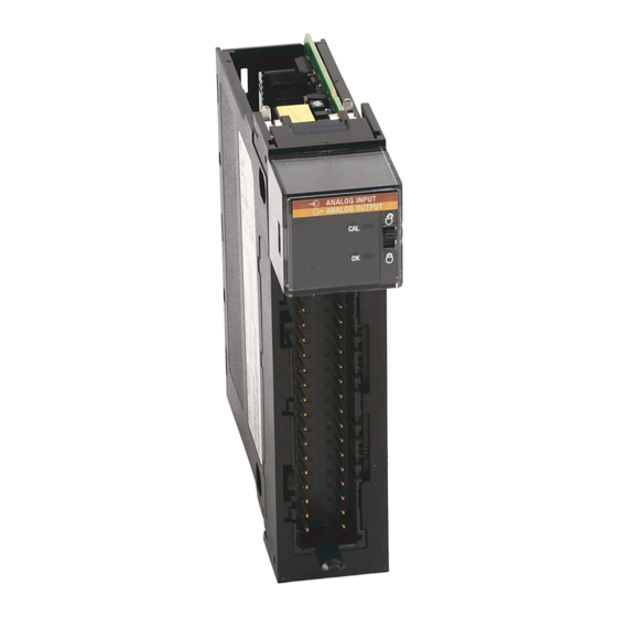
Page 6: Identify The Module Components
6 ControlLogix High Speed Analog I/O Module Identify the Module Components You received the following components with your order: • 1756-IF4FXOF2F module • Removable Terminal Block (RTB) door label If you did not receive these components, contact your local distributor Rockwell Automation sales office. This module mounts in a ControlLogix... -
Page 7: Note The Power Requirements
ControlLogix High Speed Analog I/O Module 7 Note the Power Requirements This module receives power from the 1756 chasis power supply and requires 2 sources of power from the backplane: • 375mA at 5.1V dc • 100mA at 24V dc Add this current/power value (4.3W) to the requirements of all other modules in the chassis to prevent overloading the power supply. -
Page 8: Key The Removable Terminal Block/Interface Module
8 ControlLogix High Speed Analog I/O Module Key the Removable Terminal Block/Interface Module Use the wedge-shaped keying tabs and U-shaped keying bands to prevent connecting the wrong wires to your module. Key positions on the module that correspond to unkeyed positions on the RTB. - Page 9 ControlLogix High Speed Analog I/O Module 9 Connect grounded end of the cable Ground one end of the cable only. Follow the steps below. 1. Prepare one end of the cable for grounding. a. Remove a length b. Pull the foil shield c.
- Page 10 10 ControlLogix High Speed Analog I/O Module Connect ungrounded end of the cable 1. Prepare the non-grounded end of the cable. a. Remove a length b. Pull the foil shield c. Cut the foil shield and drain of cable jacket and bare drain wire back to the cable from the...
-
Page 11: Wire The Module
ControlLogix High Speed Analog I/O Module 11 Wire the Module You can only connect wiring to your module through an RTB or IFM. The example below shows how to wire the module. 1756-IF4FXOF2F Current Mode Wiring Diagram (-) i +IN-1/V +IN-0/V 2-Wire IN-1/I... - Page 12 12 ControlLogix High Speed Analog I/O Module 1756-IF4FXOF2F Voltage Mode Wiring Diagram User +IN-1/V +IN-0/V Analog IN-1/I IN-0/I Input -IN-1 -IN-0 Device +IN-3/V +IN-2/V IN-3/I IN-2/I Shield -IN-2 -IN-3 ground Not used Not used Not used Not used V OUT-1 V OUT-0 I OUT-1 I OUT-0...
-
Page 13: Assemble The Removable Terminal Block And The Housing
ControlLogix High Speed Analog I/O Module 13 Assemble the Removable Terminal Block and the Housing 1. Align the grooves at the bottom of the housing with the side edges of the RTB. Groove Side edge of the RTB Groove Strain relief area Side edge of the RTB 2. -
Page 14: Check The Indicators
14 ControlLogix High Speed Analog I/O Module Check the Indicators The indicators show CAL status (green) and a bi-colored LED for module "OK" (red/green). ANALOG INPUT ANALOG OUTPUT 42741 During power up, an indicator test is done and the following occurs: •... -
Page 15: Remove The Removable Terminal Block From The Module
ControlLogix High Speed Analog I/O Module 15 Remove the Removable Terminal Block from the Module If you need to remove the module, you must remove the RTB first. When you insert or remove the module while WARNING backplane power is on, an electrical arc can occur. -
Page 16: See 1756-If4Fxof2F Specifications
16 ControlLogix High Speed Analog I/O Module 1756-IF4FXOF2F Specifications General Module Specifications Module Location 1756 ControlLogix chassis Backplane Current 375mA @ 5.1V dc & 100mA @ 24V dc (No module external (Total backplane power = 4.3W) power requirements) PowerDissipation within Module 4.3W voltage 4.7W current Thermal Dissipation... - Page 17 ControlLogix High Speed Analog I/O Module 17 Environmental Conditions (continued) Shock IEC60068-2-27:1987, Test Ea (Unpackaged shock, ES#002) Operating 15g Non-operating 30g Emissions CISPR 11 Group 1, Class A ESD Immunity IEC 61000-4-2 6kV contact discharges 15kV air discharges Radiated RF Immunity IEC 61000-4-3 10V/m with 1kHz sine-wave 80%AM from 30MHz to 2000MHz...
- Page 18 18 ControlLogix High Speed Analog I/O Module Input Specifications Number of Inputs 4 differential inputs Input Range Selections +/- 10.5V, 0-10.5V, 0-5.25V, 0-21ma overrange indication when exceeded Voltage Resolution Approximately 14 bits across +/-10.5V dc (21V total) +/- 10.5V range 1.3mV/bit - 14-bit effective 0-10.5V range 1.3mV/bit - 13-bit effective...
- Page 19 ControlLogix High Speed Analog I/O Module 19 Accuracy at 25°C 0.05% of selected range immediately after calibration Current (4mA to 21mA range) Better than 0.1% of range with calibration interval Voltage (-10.4 to +10.4V range) Better than 0.1% of range with calibration interval Calibration Interval 12 months typical 50 µ...
- Page 20 Informations sur l’utilisation de cet équipement en environnements dangereux : Les produits marqués "CL I, DIV 2, GP A, B, C, D" ne conviennent qu’à une utilisation en environnements de Classe I Division 2 Groupes A, B, C, D dangereux et non dangereux. Chaque produit est livré avec des marquages sur sa plaque d’identification qui indiquent le code de température pour les environnements dangereux.
Need help?
Do you have a question about the ControlLogix 1756-IF4FXOF2F and is the answer not in the manual?
Questions and answers