
Related Manuals for Atmel ICE50


Summary of Contents for Atmel ICE50
- Page 1 ICE50 ....................User Guide...
-
Page 3: Table Of Contents
1.1.1 Warnings ....................1-1 1.1.2 Tips.....................1-1 1.1.3 Workaround ..................1-1 1.1.4 Checklists ...................1-1 1.1.5 Related Documentation ..............1-2 ICE50 Firmware History ................1-2 1.2.1 Version 1.0 ..................1-2 1.2.2 Version 1.1 ..................1-2 1.2.3 Version 1.2 ..................1-2 ICE50 Known Issues.................1-2 1.3.1 User Break in Sleep Mode..............1-2 1.3.2... - Page 4 Digital I/O..................3-12 3.5.3 Analog Comparator ................3-14 3.5.4 A/D Converter...................3-14 Power System Description ..............3-15 3.6.1 Power Supply ...................3-15 3.6.2 ICE50 Power System ...............3-15 3.6.3 Target Application Power Requirements ..........3-16 Probe Description ...................3-17 3.7.1 Probe Description ................3-17 3.7.2 External Clock Signal ...............3-18 3.7.3 Internal Clock Signal Provided by AVR Studio .........3-18...
- Page 5 Section 7 Trace..................... 7-1 Enabling Trace in AVR Studio..............7-1 The Trace Window ..................7-2 Contents of Trace Window Based on Instruction (ICE50)......7-4 Accessing External Data Memory (ICE50 Trace) ........7-14 Interrupt Handling (ICE50 Trace) ............7-14 Reset (ICE50 Trace) ................7-15 Save Trace Buffer to File (ICE50) ............7-15 Sleep (ICE50 Trace) ................7-15...
- Page 6 Table of Contents Section 8 Troubleshooting ..................8-1 Troubleshooting Guide................8-1 ICE50 User Guide 2523A–AVR–11/02...
-
Page 7: Preface
1.1.4 Checklists Once comfortable with the configurtion and use of the ICE50, the checklists at the end of these sections can be used for fast setup of a new project. The checklists are of great help for getting the debugging system on-line without prob- lems. -
Page 8: Related Documentation
Brown-out Detection (BOD): Selection of Brown-out Voltage is now enabled for all parts. Mega8: Reset Disable Fuse added to ICE50 options. ICE50 Known There are some known issues in the ICE50 that users needs to be aware of. Issues 1.3.1 User Break in Sleep User break in sleep mode is not supported. -
Page 9: Reporting Problems
Preface Reporting Problems with AVR Studio can be reported to avr@atmel.com. Problems with beta releases can be reported to avrbeta@atmel.com. Problems ICE50 User Guide 2523A–AVR–11/02... - Page 10 Preface ICE50 User Guide 2523A–AVR–11/02...
-
Page 11: Introduction
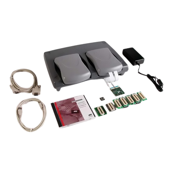
Section 2 Introduction ATICE50 is an advanced In-Circuit Emulator that covers a wide range of the eight bits AVR microcontrollers from Atmel. This section gives a brief introduction to it’s features. ICE50 Contents Figure 2-1. The ATICE50 contains the following items: ICE50 Main Unit/Pod/Two FPC (Flexible Printed Circuit) Cables &... -
Page 12: Ice50 Features
ICE50 Quick Start Guide ICE50 Features The ICE50 In-circuit Emulator is a High-end Emulator from Atmel designed to emulate a wide range of AVR devices. The ICE50 is controlled by AVR Studio 4.0 or later. Present, the following devices are supported: – ATtiny26 –... -
Page 13: System Requirements
The following minimum requirements apply for the ICE50. Requirements 2.3.1 Hardware For using the ICE50 with AVR Studio, a Pentium 233 MHz (or more) class personal Requirements computer with following specifications is recommended: 64 MByte RAM, or more 20 MByte of free hard disk (HD) space... - Page 14 Introduction ICE50 User Guide 2523A–AVR–11/02...
-
Page 15: General Description
“emulate” the behaviour of another piece of hardware. In the case of the ICE50, it is designed to behave as a wide range of AVR devices. Exact emulation is the goal for all emulators and the ICE50 offers the highest possible level of compatibility. -
Page 16: Main Emulator Unit
3.2.2 Status LEDs There are three LEDs on the front of the ICE50 cabinet. One red, one red/green duo LED and one green LED. All these LEDs give important status information on the ICE50 and which mode it is operating in. The picture below shows a close-up of the LEDs. - Page 17 3.2.2.1 Red Power LED The red LED is the power indicator LED. This will be lit if power on the ICE50 is turned on and the power system is working correctly. If the LED stays off after power on, make sure the power supply meets the requirements of the ICE50.
-
Page 18: Pod Bay
General Description POD Bay The ICE50 has a very flexible architecture that will ensure a long product life. The differ- ent AVR devices are characterised through their number of I/O pins and analog features. Both the I/O pins and the analog features are implemented on the POD board. -
Page 19: Expansion Bay
RS-232C interface. This is the communication protocol used by COM ports on PCs. The communication runs at 115200 bit/s, no parity, 8 data bits, 1 stop bit, (N81). For information on how to connect the ICE50 to a PC see the Connecting ICE50 to PC section. See Figure 3-6. -
Page 20: Power Connector
3.3.8 Power Connector The Power Connector on the ICE50 system is a standard type with 2.1 mm center tap. Ground should be connected to the center tap. For more information about power requirements and operating conditions see the Power System Description. See Figure 3-7. -
Page 21: T26 Personality Adapter
When connecting the Personality Adapter to the Probe, make sure to align the circles on the Probe and Per- sonality Adapter as shown above. Figure 3-9. t26 Personality Adapter Note: 1. SNR: A9902.3.1370.A 3.4.2.1 Supported Devices ATtiny26 ICE50 User Guide 2523A–AVR–11/02... -
Page 22: T28 And T29 Personality Adapter
When connecting the Personality Adapter to the Probe, make sure to align the circles on the Probe and Per- sonality Adapter as shown above. Figure 3-11. m8 Personality Adapter Note: 1. SNR: A9902.3.1390.C 3.4.4.1 Supported Devices ATmega8 ICE50 User Guide 2523A–AVR–11/02... -
Page 23: M32 Personality Adapter
When connecting the Personality Adapter to the Probe, make sure to align the circles on the Probe and Personality Adapter as shown above. Figure 3-13. m162 Personality Adapter Note: 1. SNR: A9902.3.1300.B 3.4.6.1 Supported Devices ATmega162 ICE50 User Guide 2523A–AVR–11/02... -
Page 24: M128 Personality Adapter
The circle marked on the Probe should align with pin 1 on the m128 adapter. Figure 3-14. m128 Personality Adapter Note: 1. SNR: W10635SDF 3.4.7.1 Supported Devices ATmega128 3.4.8 m169 Personality Figure 3-15. m169 Personality AdapterFigure 1 Adapter Note: 1. SNR: W10634SDF 3.4.8.1 Supported Devices ATmega169 3-10 ICE50 User Guide 2523A–AVR–11/02... -
Page 25: Pod Description
POD modules that support the functionality of the new devices. 3.5.1 POD Description The ICE50 POD is shown in Figure 3-16. It connects to the main unit through two dock- ing connectors. When connecting or disconnecting the POD do not use excessive force as this might damage the POD. -
Page 26: Digital I/O
General Description 3.5.2 Digital I/O The Digital IO ports of the ICE50 are realized as shown in Figure 3-17 using CMOS buff- ers and voltage converters. Figure 3-17. Digital I/O DIGITAL I/O LEVEL CONVERTER Emulator Target PULLUP (DDRxy & PORTxy) - Page 27 . At 2V V the buffers are able to sink 25 mA with a maximal output low voltage (VOLmax) of 1V. The hysteresis voltage for the input buffers are typically 0.8V at 3V V and 1.2V at 5.5V ICE50 User Guide 3-13 2523A–AVR–11/02...
-
Page 28: Analog Comparator
ACBG AIN0 100R AIN1 ACME ADEN ADC Multiplexer Output 3.5.4 A/D Converter The block diagram of the ICE50 AD converter is shown in Figure 3-21. Figure 3-21. ICE50 AD Converter A/D Converter 330Ω ADC7 330Ω ADC6 330Ω ADC5 330Ω ADC4... -
Page 29: Power System Description
2.1 mm center tap. Ground is connected to the center tap. 3.6.2 ICE50 Power System The ICE50 has an internal power regulator designed to deliver regulated voltages for use by the ICE itself. The power system is not designed to provide external power to the target application. -
Page 30: Target Application Power Requirements
165 mA Note: The Digital I/O drive capabilities of the ICE50 POD differ slightly from what can be expected in the actual device. For details on the Digital I/O drive capabilities compared to the actual device, please see the Digital I/O section of the POD description. -
Page 31: Probe Description
General Description Probe The ICE50 probe is the link between the flex cable going out from the POD and the Per- sonaliy Adapter that fits into the target application. The main purpose of the probe is to Description route all the signals from the flex cable to the appropriate pins of the personality adapter. -
Page 32: External Clock Signal
Section 3.7.6 and Section 3.7.7. The Probe version can be found on top of the back side of the Probe (left side of the right picture above). 3.7.1.2 ICE50 Probe version Version A9902.3.1200.E of the Probe supports the following clock options: A9902.3.1200.E... -
Page 33: Internal Rc Oscillator
XTAL2 pin. See special section for a description of how to set up the XTAL2 clock. 3.7.7 External RC External RC Oscillator is not supported on the ICE50 probe. Instead, configure the emu- Oscillator lator to use the internal programmable clock. The XTAL1 and XTAL2 pins will then be tristated. -
Page 34: Using The Test Adapter
Select the test that should be run, and press the “Run” button to start the test. Finally, the test program will show the status of the test. Note: AVR Studio 4.0 or later is required for ICE50 support. AVR Studio 3.x versions will not work with ICE50! Tip! AVR Studio is constantly being updated. -
Page 35: Connecting Ice50
AVR Studio can not force control over a COM port. If other equipment or software driv- ers have control of the COM port (eg. IrDA, PDA, Scanner.. ) communication with the ICE50 will fail. Make sure that no other software has control of the COM port that ICE50 is connected to. - Page 36 Connecting ICE50 connecting or disconnecting the ICE50 from the host PC, make sure that the ICE50 is not powered. 1. Inserting the personality adapter. Make sure that pin 1 on the personality adapter corresponds with pin 1 on the target socket/footprint.
- Page 37 The bottom part that should be soldered into the target application, and the top part that interface with the ICE50 Probe. When mounting the TQFP adapter, make sure that the adapter is soldered into the application with the correct orientation.
-
Page 38: Ice50 Power-Up Sequence
Once the Probe and Personality Adapter are connected, continue by correct Power-up sequence. ICE50 Power-up When the ICE50 is properly connected to the target and the host PC, the power can be turned on. The following procedure is recommended to ensure proper communication Sequence between the ICE50 and AVR Studio. -
Page 39: Configuring Avr Studio
Section 5 Configuring AVR Studio When the ICE50 is properly connected to the target application, the next step is to set up the correct device configuration in AVR Studio. This is required when an application project is opened for the first time, and can later be changed in the emulator options menu. -
Page 40: Avr Studio Configuration Quick Start Guide
Configuring AVR Studio AVR Studio Follow the procedure described below to configure the ICE50: Configuration 1. Connect the ICE50 and start AVR Studio. See Connecting ICE50 for a more Quick Start detailed description. Guide 2. Select between creating a new or opening an existing AVR Assembler project. -
Page 41: Device Selection
Click this icon if this part is to be loaded into the ICE50. A total of four part files can be contained in the ICE50 at the same time. Some part files contain two AVR emulator parts. The status bar at the right side indicates how many part files ICE50 contains. - Page 42 See Figure 5-4. The ICE Reset button resets the ICE while the set Default button loads the default settings. ICE reset performs the same reset as the reset button on the back of the ICE50. ICE50 User Guide 2523A–AVR–11/02...
-
Page 43: Fuses And Lock Bits
Bits view. Configuration is performed in the other views. In AVR Studio go to Debug->ICE50 options. Highlight Fuses and Lock bits. It is now possible to view 4 different settings. Note that Fuses marked with “!” do not affect emulation. - Page 44 Fuse. “0” indicates on, “1” indicates off. The Fuse settings can not be edited here. See the datasheet for the part when configuring the Fuses. Note that Fuses marked with “!” do not affect emulation. See Figure 5-8. ICE50 User Guide 2523A–AVR–11/02...
- Page 45 Configuring AVR Studio Figure 5-8. High Fuse Settings Tip! Not all fuse settings are supported by the ICE50. The following fuses are ignored: – OCDEN. On Chip debug is not available in ICE50. – SPIEN. Serial Programming not available. – EESAVE. Not available in ICE50.
-
Page 46: Lock Bits
By pressing Lock bits the tree expands and it is possible to see the Lock bit settings. “0” indicates on, “1” indicates off. The fuse settings can not be edited here. See the datasheet for the part when configuring the Lock bits. See Figure 5-9. Figure 5-9. Lock Bits Settings ICE50 User Guide 2523A–AVR–11/02... -
Page 47: Ice Status
See figure below. The ICE Reset button performs a warm emulator reset and can be used instead of the reset button on the back of the ICE50 while the Set Default button loads the default setting for the actual part. Figure 5-10. ICE Status Reports for the different FPGA configuration files and the hardware revisions in the dif- ferent PCB's are also shown. - Page 48 Configuring AVR Studio Figure 5-11. ICE Staus Window 5-10 ICE50 User Guide 2523A–AVR–11/02...
-
Page 49: Boot Block Options
This menu is only available for AVR parts with Boot Block. Figure 5-12. Boot Block Options Note: AVR Studio 4.0 or later is required for ICE50 support. AVR Studio 3.x versions will not work with ICE50! ICE50 User Guide 5-11... -
Page 50: Special
In addition two buttons called ICE Reset and Set Default are located in the lower left cor- ner. The ICE Reset button resets the ICE while the Set Default button loads the default setting. ICE reset performs the same reset as the reset button on the back of the ICE50. Downloading AVR Studio will check if newer files are available in the ICE50 dat file, and prompt the user whether an upgrade should be performed. -
Page 51: Upgrading The Ice50 Firmware
Upgrading the The ICE50 firmware can be upgraded from AVR Studio. ICE50 Firmware In AVR Studio go to Tools ->ICE50 Upgrade. The window as shown in Figure 5-14 will appear. Figure 5-14. ICE50 Upgrade Window From this window it is possible to select two buttons. The Start Upgrade button will per- form an upgrade of the ICE50. - Page 52 Configuring AVR Studio Figure 5-15. Version Information 5-14 ICE50 User Guide 2523A–AVR–11/02...
-
Page 53: Special Considerations
If you experience problems not described in this section, please see the troubleshooting section for more information. Electrical ICE50 is created to emulate an actual AVR device in detail. When it comes to electrical compatibility some issues must be considered. They are described in this section. Compatibility 6.1.1... -
Page 54: Sleep Mode
110 mA 165 mA Clock Options The Current version of the ICE50 Probe has limited support for Clock options. See Available Clock Options for an overview of the supported modes. Other modes can however easily be emulated using the modes above. -
Page 55: Trace
Section 7 Trace The ICE50 contains a 144-bit wide, 128K levels deep Trace Buffer. This document describes the contents of the AVR Studio Trace Buffer view. Enabling Trace 1. To enable Trace in AVR Studio select “Trace Normal” from the trace toolbar pull- down menu. -
Page 56: The Trace Window
Figure 7-6. Trace Buffer The Trace function of the ICE50 traces the program execution every clock cycle trace every single cycle in the execution. The Trace view contains the columns described below. A more detailed description of the contents of each column for the individual AVR instruction is found in the section: Contents of Trace Window based on Instruction. - Page 57 Status Register Column (SR): Contains the AVR Status Register. Function ID (PS): This column contains the Function ID number. Interrupt Acknowledge Column: If an interrupt routine is invoked this column will contain a “1” else a “0”. ICE50 User Guide 2523A–AVR–11/02...
- Page 58 Address of instruction Result of decrementation Z,N,V,S Will never appear (is TST Rd disassembled to AND Z,N,V,S instruction) CLR Rd Address of instruction Result (always 0x00) Z,N,V,S Will never appear (is SER Rd disassembled to LDI instruction) ICE50 User Guide 2523A–AVR–11/02...
- Page 59 2. Address of next instruction 2. Result of multiplication 2. N/A 2. N/A 1. Address of instruction 1. N/A 1. N/A 1. N/A FMULSU Rd, Rr 2. Address of next instruction 2. Result of multiplication 2. N/A 2. N/A ICE50 User Guide 2523A–AVR–11/02...
- Page 60 2. Value read 2. Value read from (Z) 1. Address of instruction 1. N/A 1. N/A) 1. N/A LDD Rd, Z+q 2. Address read 2. Address of next instruction 2. Value read 2. Value read from (Z+q ICE50 User Guide 2523A–AVR–11/02...
- Page 61 2. N/A 2. Value written to (Z+q) 1. Address of instruction 1. N/A 1. N/A 1. N/A STS k, Rr 2. Address of address-part of 2. Address written 2. N/A 2. Value written instruction to (k) ICE50 User Guide 2523A–AVR–11/02...
- Page 62 2. Stack Pointer 2. Value pushed 1. Address of instruction 1. N/A 1. N/A 1. N/A POP Rd 2. Address of next instruction 2. Value popped 2. Stack Pointer 2. Value popped Note: 1. Internal Memory ICE50 User Guide 2523A–AVR–11/02...
- Page 63 1. N/A 2. Address of skipped 2. N/A 2. N/A 2. N/A instruction, first word 3. Address of skipped 3. N/A 3. N/A 3. N/A instruction, second word Address of instruction Address of instruction Address of instruction ICE50 User Guide 2523A–AVR–11/02...
- Page 64 2. N/A 2. N/A 2. N/A 1. Address of instruction 1. N/A 1. N/A 1. N/A BREQ 1. Address of instruction 1. N/A 1. N/A 1. N/A 2. N/A 2. N/A 2. N/A 2. N/A 7-10 ICE50 User Guide 2523A–AVR–11/02...
- Page 65 2. N/A 2. N/A 2. N/A 1. Address of instruction 1. N/A 1. N/A 1. N/A BRTC 1. Address of instruction 1. N/A 1. N/A 1. N/A 2. N/A 2. N/A 2. N/A 2. N/A ICE50 User Guide 7-11 2523A–AVR–11/02...
- Page 66 2. N/A Notes: 1. Stack in internal memory 2. Condition not met (no skip) 3. Condition met, skipping 1 word instruction 4. Condition met, skipping 2 word instruction 5. Branch taken 6. Branch not taken 7-12 ICE50 User Guide 2523A–AVR–11/02...
- Page 67 Address of instruction Address of instruction Address of instruction Address of instruction Address of instruction Address of instruction Address of instruction Address of instruction Address of instruction Address of instruction Address of instruction Address of instruction ICE50 User Guide 7-13 2523A–AVR–11/02...
-
Page 68: Accessing External Data Memory (Ice50 Trace)
0x2F before it starts executing from the interrupt vector (in this case, interrupt vector 0x000013). After the (in this case very simple) interrupt program has completed, execution resumes. Figure 7-7. Example Code 7-14 ICE50 User Guide 2523A–AVR–11/02... -
Page 69: Reset (Ice50 Trace)
The trace buffer will be filled with sleep instructions for each cycle as long as the microcontroller is in sleep mode. ICE50 User Guide 7-15 2523A–AVR–11/02... - Page 70 Trace 7-16 ICE50 User Guide 2523A–AVR–11/02...
- Page 71 – Can't establish communication. Check if other equipment has control over the COM port, IrDA etc. – Cycle power and restart AVR Studio – Do no use serial port I/O card or USB to serial adapter – USB communication is not yet supported ICE50 User Guide Rev. 2523A–AVR–11/02...
- Page 72 Troubleshooting ICE50 User Guide 2523A–AVR–11/02...
- Page 73 No licenses to patents or other intellectual property of Atmel are granted by the Company in connection with the sale of Atmel products, expressly or by implication. Atmel’s products are not authorized for use as critical components in life support devices or systems.
- Page 74 Mouser Electronics Authorized Distributor Click to View Pricing, Inventory, Delivery & Lifecycle Information: Microchip ATICE50 ATICE50MEM ATICE50POD ATICE50PROBE...