Table of Contents
Advertisement
Quick Links
SMART ARM-based Microcontrollers
SAME70-XPLD
USER GUIDE
Preface
®
The Atmel
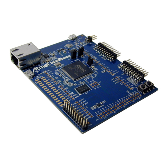
SAM E70 Xplained evaluation kit is a hardware platform to
evaluate the Atmel ATSAME70Q21 microcontroller.
Supported by the Atmel Studio integrated development platform, the kit
provides easy access to the features of the ATSAME70Q21 and explains
how to integrate the device in a custom design.
The Xplained Pro MCU series evaluation kits include an on-board
Embedded Debugger, and no external tools are necessary to program or
debug the ATSAME70Q21.
The Xplained Pro extension series evaluation kits offers additional
peripherals to extend the features of the board and ease the development of
custom designs.
Atmel-44050A-SAME70-XPLD_User Guide-12/2015
Advertisement
Table of Contents

Related Manuals for Atmel SAME70-XPLD


Summary of Contents for Atmel SAME70-XPLD
-
Page 1: Preface
SAM E70 Xplained evaluation kit is a hardware platform to evaluate the Atmel ATSAME70Q21 microcontroller. Supported by the Atmel Studio integrated development platform, the kit provides easy access to the features of the ATSAME70Q21 and explains how to integrate the device in a custom design. -
Page 2: Table Of Contents
4.1. Microcontroller..........................11 4.2. Power Distribution........................11 4.3. Connectors..........................12 4.4. Peripherals..........................30 4.5. Zero Ohm Resistors........................38 4.6. Embedded Debugger Implementation..................41 5. Board Schematics....................44 6. Board Layout......................51 7. Evaluation Board/kit Important Notice..............57 Atmel SAME70-XPLD [USER GUIDE] Atmel-44050A-SAME70-XPLD_User Guide-12/2015... -
Page 3: Introduction
Introduction This user guide introduces the Atmel SAME70-XPLD evaluation kit and describes the development and debugging capabilities for applications running on a SAM E70 ARM-based embedded microcontroller. 1.1. Kit Contents • Boards – One SAME70-XPLD board • Cables – One Micro-AB type USB cable 1.2. - Page 4 On-board power regulation is performed by a 3.3V LDO User interface Reset and free user pushbutton One green user LED 1.3.4. Board Overview The Atmel SAME70-XPLD is a hardware platform to evaluate the Atmel ATSAME70Q21. Atmel SAME70-XPLD [USER GUIDE] Atmel-44050A-SAME70-XPLD_User Guide-12/2015...
- Page 5 It offers a set of features that enables the ATSAME70Q21 user to get started with the SAM V71, SAM V70, SAM E70 and SAM S70 peripherals right away and to get an understanding of how to integrate the device in their own design. The SAME70-XPLD board is equipped with the interface connectors described in Table 1-3.
-
Page 6: Getting Started
Connect a USB cable (Standard-A to Micro-B or Micro-AB) between the PC and the DEBUG USB port of the board. When the Atmel SAME70-XPLD is connected to your computer for the first time, the operating system will ® perform a driver software installation. The driver file supports both 32- and 64-bit versions of Microsoft ®... -
Page 7: Xplained Pro
When an Xplained Pro extension is connected to an Xplained Pro MCU board the information is read and sent to Atmel Studio. The Atmel Kits extension, installed with Atmel Studio, will give relevant information, code examples, and links to relevant documents. The table below shows the data fields stored in the ID chip with example content. -
Page 8: Power Sources
Embedded Debugger USB (J900 connector) Info: USB sources supposedly provide a maximum current of 500mA. Calculate the power budget of your system, there is a possiblity this could be not enough if your SAME70-XPLD also connects to power demanding extension boards. -
Page 9: Xplained Pro Power Header
The power header can only be used as supply for external peripherals or extension boards. Care must be taken not to exceed the total current limitation of the on-board regulator when using the 3.3V pin. Atmel SAME70-XPLD [USER GUIDE] Atmel-44050A-SAME70-XPLD_User Guide-12/2015... - Page 10 Table 3-4 Xplained Pro Power Header Pin number Pin name Description not connected Ground VCC_5V0 Output: unregulated 5V (output, derived from one of the input sources) VCC_3V3 Output: regulated 3.3V (output, used as main power supply for the kit) Atmel SAME70-XPLD [USER GUIDE] Atmel-44050A-SAME70-XPLD_User Guide-12/2015...
-
Page 11: Hardware User Guide
4.1. Microcontroller The SAME70-XPLD board is built around the ATSAME70Q21 in a 144-lead LQFP package. It is a low- power ARM Cortex-M7 application microcontroller achieving high-performance computing device and embedding a wide range of communication peripherals. It features a combination of user interface functionalities and high data rate IOs, camera interface, 10/100 Ethernet ports, high-speed USB and SD Card. -
Page 12: Connectors
4.3. Connectors These sections describe the implementation of all connectors and headers on SAME70-XPLD and their connection to the ATSAME70Q21. The tables of connections in these sections also describe which signals are shared between the headers and on-board functionality. The figure below shows all available connectors and jumpers on the SAME70-XPLD. - Page 13 4.3.1. Extension Headers The Xplained Pro headers EXT1 and EXT2 on SAME70-XPLD give access to the I/O of the microcontroller in order to expand the system, e.g. by connecting extensions boards. The headers have a pitch of 2.54mm. Table 4-1 EXT1 Header...
- Page 14 Embedded Debugger 12 [I2C_SCL] TWCK0 Camera Connector, EXT1 Header, J500 Header (Arduino Shield), AT24MAC402, Embedded Debugger 13 [UART_RX] PA21 RXD1 J507 Header (Arduino Shield), Embedded Debugger 14 [UART_TX] TXD1 J507 Header (Arduino Shield), Embedded Debugger Atmel SAME70-XPLD [USER GUIDE] Atmel-44050A-SAME70-XPLD_User Guide-12/2015...
- Page 15 (location and footprint) compatible with the Arduino R3 shields. Important: As the SAM E70 signals have a voltage level of 3.3V, 5V level shields cannot properly function with SAME70-XPLD. In addition to its standard IO functionality, the SAM E70 microcontroller can provide alternate functions to external IO lines available on the J500 to J507 headers.
- Page 16 PIO multiplexing and alternate function selection. Caution: Like the Arduino Due, SAME70-XPLD runs at 3.3V and the maximum voltage that the I/O pins can tolerate is 3.3V, connecting higher voltages e.g. 5V to those I/O pin could damage the board.
- Page 17 Info: By default, pin 4 is connected to PD21 PIO through a 0R serial resistor. Alternately, it can be connected to PD11. To do so R210 must be removed and R212 must be mounted. Atmel SAME70-XPLD [USER GUIDE] Atmel-44050A-SAME70-XPLD_User Guide-12/2015...
- Page 18 System ground Not connected by default. Optional 5Vcc supply for any Arduino Shield. Info: Pin 8 is connected to the SAME70-XPLD board through an 0R serial resistor. It is necessary to mount 0R resistor R623 to enable the functionality. Atmel SAME70-XPLD [USER GUIDE]...
- Page 19 PC12 AFE1_AD3 TIOB8 CANRX1 Info: Pins 6, 7, 8 are connected to SAM E70 PIOs through 0R serial resistors. It is necessary to mount them to enable the PIO functionality, respectively R214, R216, R236. Atmel SAME70-XPLD [USER GUIDE] Atmel-44050A-SAME70-XPLD_User Guide-12/2015...
- Page 20 Table 4-6 J503 Header IOs Pin PCB Primary Function Alternate Function Marking PWMC0_PWMH1 WKUP2 PC19 PWMC0_PWMH2 PD11 PWMC0_PWMH0 PD27 SPI0_NPCS3 PWMC0_PWML3 TWD2 PCK0 UTXD1 PD10 PWMC0_PWML0 PWMC1_PWML3 URXD1 WKUP4 PD30 UTXD3 AFE0_AD0 (TXD) PD28 URXD3 TWCK2 CANRX1 (RXD) Atmel SAME70-XPLD [USER GUIDE] Atmel-44050A-SAME70-XPLD_User Guide-12/2015...
- Page 21 Marking Function PD24 TCLK11 PWMC0_PWML0 PA10 PWMC0_PWMEXTRG AD10 PA22 PWMC0_PWMEXTRG AD11 PC31 AFE1_AD6 TCLK5 DAC0 PB13 DAC0 PWMC0_PWML2 PCK0 DAC1 DAC1 PWMC1_PWML0 SPI1_NPCS1 CANRX CANRX0 RTS0 PCK2 AFE0_AD2 WKUP12 CANTX CANTX0 AFE0_AD5 SPI0_NPCS0 CTS0 Atmel SAME70-XPLD [USER GUIDE] Atmel-44050A-SAME70-XPLD_User Guide-12/2015...
- Page 22 CANRX1 URXD3 WKUP5 4.3.2.7. J506 Header J506 is a 2x3-pin header with 2.54mm pitch. It is not populated by default and can be used to connect to Arduino Shields. It includes the SPI interface. Atmel SAME70-XPLD [USER GUIDE] Atmel-44050A-SAME70-XPLD_User Guide-12/2015...
- Page 23 J507 is a 2x18-pin header with 2.54mm pitch. It is not populated by default and can be used to connect to Arduino Shields. It includes PWM, Timer Counters, Audio Transmit interface, CAN interface, USART1 and USART2 interfaces and four UART interfaces. Atmel SAME70-XPLD [USER GUIDE] Atmel-44050A-SAME70-XPLD_User Guide-12/2015...
- Page 24 PA18 PCK2 PWMC1_PWMEXTR PWMC0_PWMH1 AFE1_AD0 GTSUCOMP PWMC0_PWMH0 AFE0_AD10 RXD0 PD17 SCK2 PD19 CTS2 UTXD4 PD18 RTS2 URXD4 PWMC1_PWML3 URXD1 WKUP4 Not Connected PA29 TCLK2 WKUP1 PWMC0_PWML0 TIOB0 Not Connected PA26 PWMC1_PWMFI1 TIOA2 Not Connected Atmel SAME70-XPLD [USER GUIDE] Atmel-44050A-SAME70-XPLD_User Guide-12/2015...
- Page 25 PC12 CANRX1 AFE1_AD3 TIOB8 PC14 CANTX1 TCLK8 System ground System ground 4.3.3. Camera Connector A 2×15-pin, 100mil pin-header camera connector is implemented to give access to the SAM E70 parallel Image Sensor Interface (ISI). Atmel SAME70-XPLD [USER GUIDE] Atmel-44050A-SAME70-XPLD_User Guide-12/2015...
- Page 26 J500 Header (Arduino Shield), Embedded Debugger PCK0 EXT2 Header, J503 Header (Arduino Shield) PD25 ISI_VSYNC EXT1 Header, J500 Header (Arduino Shield) PD24 ISI_HSYNC J504 Header (Arduino Shield) PA24 ISI_PCK EXT2 Header, J507 Header (Arduino Shield) Atmel SAME70-XPLD [USER GUIDE] Atmel-44050A-SAME70-XPLD_User Guide-12/2015...
- Page 27 (Arduino Shield) PD31 ISI_D11 EXT2 Header 4.3.4. The SAME70-XPLD board features a Micro-USB connector that implements the SAM E70 USB high speed interface. This connector is labeled as TARGET USB on the board. Figure 4-13 USB Interface Schematic VCC_USB ATMEL HSDP...
- Page 28 VDDCORE Current Measurement A 100mil pin-header marked "J201" is located at the upper edge of the SAME70-XPLD board. It is not mounted by default and is replaced by a shunt trace between the two pads of the connector. All power to VDDCORE of the ATSAME70Q21 is routed through this header.
- Page 29 Figure 4-16 ERASE Chip Connector Placement J200 J200 PB12 4.3.8. Trace Connector ATSAME70Q21 supports 4-bit parallel trace. SAME70-XPLD implements a CoreSight 20 20-pin, 50-mil connector footprint on PCB bottom side (not mounted by default). Figure 4-17 Trace connector location on PCB CORESIGHT20...
-
Page 30: Peripherals
Ethernet 4.4. Peripherals 4.4.1. Clock Circuitry The SAME70-XPLD board features three clock sources: • Two crystals for the ATSAME70Q21 processor • One crystal oscillator for the Ethernet MII/RMII chip The crystals of the ATSAME70Q21 have cut-straps next to them that can be used to measure the oscillator safety factor. - Page 31 SAM E70 to use the button. 4.4.3. LEDs There is one green LED mounted on the SAME70-XPLD. It can be activated by driving the connected I/O line to a low level. Figure 4-21 LED Indicators Schematic USER LED...
- Page 32 Shared With Green LED 4.4.4. SDRAM The SAME70-XPLD features one IS42S16100F-5BL, 512K×16×2, 10ns, SDRAM chip. The SDRAM is connected to chip select NCS1. SDRAM access can be configured in the SDRAM Controller in the SAM E70. Table 4-17 SDRAM Connections on page 32 lists all I/O lines connected to the SDRAM.
- Page 33 J505 Header (Arduino Shield) 4.4.5. SD Card The SAME70-XPLD has one standard SD card slot, connected to the High-speed Multimedia Card Interface (HSMCI) of the SAM E70. Table 4-18 SD/MMC Socket J600 Signal Descriptions on page 34 lists all I/O lines connected to the SD card connector.
- Page 34 4.4.6. Ethernet The ATSAME70Q21 has a built-in 10/100 Mbps Ethernet IEEE 802.3 compatible MAC with RMII interface. The SAME70-XPLD connects the MAC to a Micrel KSZ8081RNACA RMII physical-layer transceiver (PHY), which is connected to one RJ45 Ethernet connector. ™ A unique EUI-48 address is available on every SAME70-XPLD through the on-board AT24MAC402, the EUI-48 address can be used as a MAC address for the KSZ8081RNACA.
- Page 35 LED1_LINK VCC_3V3 R701 RJ45 Table 4-19 KSZ8081RNACA Connections SAM E70 Pin Exthernet Function Shared With PHY_REFCLK J504 Header (Arduino Shield) PHY_TXEN – PHY_TXD0 – PHY_TXD1 – PHY_CRS_DV Trace Connector PHY_RXD0 Trace Connector PHY_RXD1 Trace Connector Atmel SAME70-XPLD [USER GUIDE] Atmel-44050A-SAME70-XPLD_User Guide-12/2015...
- Page 36 Auto negotiation enabled and set 100Mbps speed 4.4.7. AT24MAC402 The SAME70-XPLD features one Atmel AT24MAC402 serial EEPROM with an EIA-48 MAC address connected to the SAM E70 through I C. This AT24MAC402 is configured on the I C interface with the address 0x37h.
- Page 37 4.4.8. Debug JTAG/ICE A 2×10-pin JTAG header is implemented on the SAME70-XPLD board to enable software development and debugging of the board by using various JTAG emulators. The interface signals have a voltage level of 3.3V. Figure 4-27 JTAG/ICE Interface Schematic...
-
Page 38: Zero Ohm Resistors
System Ground 4.5. Zero Ohm Resistors The SAME70-XPLD has several zero ohm resistors that can be used to disconnect I/O pins of the ATSAME70Q21 from connectors and on-board ICs and to disconnect power signals. All Arduino pin numbers are listed in Arduino Connectors. - Page 39 TARGET_RESET Reset From JTAG Interface R403 J406 - Pin 13 TRACESWO for JTAG Interface R623 VCC_5V0 For 5V supply of any shield R624 SAM E70 Pin 3 VDDOUT Node LDO Output for current measurement Atmel SAME70-XPLD [USER GUIDE] Atmel-44050A-SAME70-XPLD_User Guide-12/2015...
- Page 40 Figure 4-28 Zero Ohm Resistors Position – Top Side R214 R216 R209 R236 R207 R208 R219 R234 R228 R220 R235 R224 R225 R402 R221 R204 R226 R227 R205 R230 R403 R229 R401 R400 Atmel SAME70-XPLD [USER GUIDE] Atmel-44050A-SAME70-XPLD_User Guide-12/2015...
-
Page 41: Embedded Debugger Implementation
R624 R122 4.6. Embedded Debugger Implementation SAME70-XPLD contains an Embedded Debugger (EDBG) that can be used to program and debug the ATSAME70Q21 using Serial Wire Debug (SWD). The EDBG also includes: • a Virtual Com port interface over UART •... - Page 42 Atmel Data Gateway Interface The Embedded Debugger features an Atmel Data Gateway Interface (DGI) by using either a SPI or I port. The DGI can be used to send a variety of data from the ATSAME70Q21 to the host PC. For further...
- Page 43 SAM E70 Pin Function Shared Functionality DGI_GPIO0 Camera Connector, Embedded Debugger PA23 DGI_GPIO1 J507 Header, Embedded Debugger PD28 DGI_GPIO2 EXT1 Header, Camera Connector,J503 Header, J505 Header, Embedded Debugger DGI_GPIO3 EXT2 Header, J503 Header, Embedded Debugger Atmel SAME70-XPLD [USER GUIDE] Atmel-44050A-SAME70-XPLD_User Guide-12/2015...
-
Page 44: Board Schematics
This section contains the following schematics: • Block Diagram • SAM E70 Device, Crystals and USB Device interface • Atmel XPRO Extended Connectors, Debug and Camera Interface Connectors • Arduino R3 Extended Connectors • Memories and Power • Ethernet 10/100 •... - Page 45 INIT EDIT INIT EDIT MODIF. MODIF. MODIF. DES. DES. DES. DATE DATE DATE VER. VER. VER. DATE DATE DATE SAME70-XPLD SAME70-XPLD SAME70-XPLD SCALE SCALE SCALE REV. REV. REV. SHEET SHEET SHEET SAME70 SAME70 SAME70 Atmel SAME70-XPLD [USER GUIDE] Atmel-44050A-SAME70-XPLD_User Guide-12/2015...
- Page 46 Figure 5-3 Atmel XPRO Extended Connectors, Debug and Camera Interface Connectors Camera Interface Connector EXT1 VCC_3V3 J401 J400 ID_EXT1 ID_1 AFE1_AD6 AFE0_AD8 {2,4} {2,4,6} PC31 PA19 {2,3,4} {2,3,4} R222 ISI_PWD PWMC0_H0 TIOB5 {2,4} PC19 {2,3,4} {2,4} PA13 PC30 TWCK0 TWD0 R203...
- Page 47 INIT EDIT MODIF. MODIF. MODIF. DES. DES. DES. DATE DATE DATE VER. VER. VER. DATE DATE DATE SAME70-XPLD SAME70-XPLD SAME70-XPLD SCALE SCALE SCALE REV. REV. REV. SHEET SHEET SHEET Shield Connectors Shield Connectors Shield Connectors Atmel SAME70-XPLD [USER GUIDE] Atmel-44050A-SAME70-XPLD_User Guide-12/2015...
- Page 48 MODIF. DES. DES. DES. DATE DATE DATE VER. VER. VER. DATE DATE DATE SAME70-XPLD SAME70-XPLD SAME70-XPLD SCALE SCALE SCALE REV. REV. REV. SHEET SHEET SHEET Memory & Power Memory & Power Memory & Power Atmel SAME70-XPLD [USER GUIDE] Atmel-44050A-SAME70-XPLD_User Guide-12/2015...
- Page 49 INIT EDIT INIT EDIT MODIF. MODIF. MODIF. DES. DES. DES. DATE DATE DATE VER. VER. VER. DATE DATE DATE SAME70-XPLD SAME70-XPLD SAME70-XPLD SCALE SCALE SCALE REV. REV. REV. SHEET SHEET SHEET Ethernet Ethernet Ethernet Atmel SAME70-XPLD [USER GUIDE] Atmel-44050A-SAME70-XPLD_User Guide-12/2015...
- Page 50 INIT EDIT MODIF. MODIF. MODIF. DES. DES. DES. DATE DATE DATE VER. VER. VER. DATE DATE DATE SAME70-XPLD SAME70-XPLD SAME70-XPLD SCALE SCALE SCALE REV. REV. REV. SHEET SHEET SHEET Embedded Debugger Embedded Debugger Embedded Debugger Atmel SAME70-XPLD [USER GUIDE] Atmel-44050A-SAME70-XPLD_User Guide-12/2015...
-
Page 51: Board Layout
R234 R228 R235 R220 R224 R225 R402 R221 AD10 R204 R226 AD11 R227 R205 R230 R403 U600 DAC0 D20 R229 R602 C600 R601 R603 RESET R401 DAC1 R600 AT24MAC402 CANRX R400 CANTX J507 JTAG Atmel SAME70-XPLD [USER GUIDE] Atmel-44050A-SAME70-XPLD_User Guide-12/2015... - Page 52 C917 C918 R617 PD30 PC13 PC13 PD30 C921C908 PD28 PC30 PD11 PA17 C922 C920 PD26 PC19 PC12 PA24 CORESIGHT2U PD16 PD24 PA21 PD15 PA10 PD19 J403 PA22 PD20 PD18 PC31 SWD+ETM PD27 PB13 PD28 Atmel SAME70-XPLD [USER GUIDE] Atmel-44050A-SAME70-XPLD_User Guide-12/2015...
- Page 53 Figure 6-3 Top Signals Layer Atmel SAME70-XPLD [USER GUIDE] Atmel-44050A-SAME70-XPLD_User Guide-12/2015...
- Page 54 Figure 6-4 Layer 2: Ground Atmel SAME70-XPLD [USER GUIDE] Atmel-44050A-SAME70-XPLD_User Guide-12/2015...
- Page 55 Figure 6-5 Layer 3: Power Planes Atmel SAME70-XPLD [USER GUIDE] Atmel-44050A-SAME70-XPLD_User Guide-12/2015...
- Page 56 Figure 6-6 Bottom Signals Layer Atmel SAME70-XPLD [USER GUIDE] Atmel-44050A-SAME70-XPLD_User Guide-12/2015...
-
Page 57: Evaluation Board/Kit Important Notice
(WEEE), FCC, CE or UL (except as may be otherwise noted on the board/kit). Atmel supplied this board/kit "AS IS," without any warranties, with all faults, at the buyer's and further users' sole risk. The user assumes all responsibility and liability for proper and safe handling of the goods. - Page 58 DISCLAIMER: The information in this document is provided in connection with Atmel products. No license, express or implied, by estoppel or otherwise, to any intellectual property right is granted by this document or in connection with the sale of Atmel products. EXCEPT AS SET FORTH IN THE ATMEL TERMS AND...
- Page 59 Mouser Electronics Authorized Distributor Click to View Pricing, Inventory, Delivery & Lifecycle Information: Atmel ATSAME70-XPLD...