
Related Manuals for National Instruments IC-317 Series


Summary of Contents for National Instruments IC-317 Series
- Page 1 National Instruments IC-3173 Manual Get Pricing & Availability at ApexWaves.com Call Today: 1-800-915-6216 Email: sales@apexwaves.com https://www.apexwaves.com/modular-systems/national-instruments/industrial-controllers/IC-3173...
-
Page 2: Table Of Contents
USER MANUAL IC-317x Industrial Controller with Reconfigurable I/O This document describes the features of the National Instruments IC-317x and contains information about mounting and operating the device. Contents IC-3171, IC-3172, and IC-3173....................1 About the IC-317x......................1 Hardware Overview......................2 Mounting the IC-317x.....................21... -
Page 3: Hardware Overview
Figure 1. IC-317x Block Diagram RJ45 Primary Gigabit x2 DisplayPort Ethernet Port Intel Dual-Core Processor i7-5650U, i5-5350U, or Celeron 3765U 8/4 GB DDR3L x2 USB 3.0 Memory Host Ports 64/32/4 GB x4 USB 2.0 Solid-state Drive Host Ports RJ50 Serial Port PCIe RS-232/422/485 Gen 2... - Page 4 You can develop a single real-time VI to use for both your user interface and system logic. For more information, refer to the Using the Embedded UI to Access RT Target IC-317x User Manual | © National Instruments | 3...
- Page 5 VIs topic in the LabVIEW Help. For up-to-date information about supported NI cables and accessories, refer to the pricing section of the product page at ni.com. Use an appropriate adapter cable to connect a DisplayPort connector to a VGA or DVI connector.
- Page 6 Ethernet port in Device Manager. The NI GigE Vision driver (NI-GEV) does not support Wake-on-LAN. The Ethernet ports with PoE do not support Wake-on-LAN. Figure 4. Ethernet Port Pin Locations (IP20) IC-317x User Manual | © National Instruments | 5...
- Page 7 Table 2. Ethernet Port Pin Descriptions Fast Ethernet (100 Mbps) Gigabit Ethernet MDI-X BI_DA+ BI_DB+ BI_DA- BI_DB- BI_DB+ BI_DA+ No Connect BI_DC+ BI_DD- No Connect BI_DC- BI_DD- BI_DB- BI_DA- No Connect BI_DD+ BI_DC+ No Connect BI_DD- BI_DC- Digital I/O The 44-pin Digital I/O port on the IC-317x offers 8 isolated inputs, 8 isolated outputs, 2 bidirectional differential inputs (RS-422) or single-ended input lines that can be used with a quadrature encoder, and 8 bidirectional TTL lines.
- Page 8 Bidirectional TTL I/O TTL 7 Bidirectional TTL I/O Digital ground reference for TTL and differential I/O Diff 1- Bidirectional RS-422 I/O (negative side), or quadrature encoder phase B- Isolated power voltage reference output IC-317x User Manual | © National Instruments | 7...
- Page 9 Table 3. Digital I/O Pin Descriptions (Continued) Pin Number Signal Description Common ground reference for isolated inputs and outputs Iso Out 2 General purpose isolated output Iso Out 3 General purpose isolated output Common ground reference for isolated inputs and outputs Iso Out 5 General purpose isolated output Iso In 0 General purpose isolated input...
- Page 10 IC-317x to an inductive load. The following image shows an example of an isolated output wired to an external load with a flyback diode installed across the load. IC-317x User Manual | © National Instruments | 9...
- Page 11 Caution Do not draw more than 35 mA from each isolated output when V 5 V. Do not draw more than 80 mA from each isolated output when V is 24 V. Figure 7. Connecting an Isolated Output to an External Load Overcurrent Protection Circuit Digital Output...
- Page 12 Figure 9. Connecting Differential Line Drivers External Device Industrial Controller Diff In 0+ Phase A Twisted Pair – Diff In 0– Phase A Diff In 1+ Phase B Twisted Pair – Diff In 1– Phase B IC-317x User Manual | © National Instruments | 11...
- Page 13 Figure 10. Connecting Single-Ended Line Drivers External Device Industrial Controller Diff In 0+ Phase A Twisted Pair – Diff In 0– Diff In 1+ Phase B Twisted Pair – Diff In 1– TTL I/O The following image shows the circuit for a bidirectional TTL I/O. Figure 11.
- Page 14 RJ50 10-position modular plug to DB-9 serial cable 182845-01 for 1 meter cable 182845-02 for 2 meter cable 182845-03 for 3 meter cable Figure 12. RS-485/422/232 Serial Port Pin Locations (IP20) IC-317x User Manual | © National Instruments | 13...
- Page 15 Table 6. RS-485/422/232 Serial Port Pin Descriptions RS-485/422 Mode RS-232 Mode No Connect No Connect TXD- Unused TXD+ Unused No Connect No Connect No Connect No Connect RXD- RXD+ Unused Unused Unused Unused Related Information Serial Port Configuration Submenu on page 53 Serial Port Configuration Submenu on page 53 USB 3.0 Ports...
- Page 16 USB Data - USB Data + Ground for power return LED Indicators The LED indicators are located on the front panel of the device. The IC-317x provides the following LED indicators. IC-317x User Manual | © National Instruments | 15...
- Page 17 POWER LED The following table lists the POWER LED indications. Table 9. POWER LED Indications LED Color LED Pattern Indication Green Solid The IC-317x is powered from the V1 input. Yellow Solid The IC-317x is powered from the V2 input. —...
- Page 18 19 User LEDs You can define the USER1 and USER FPGA1 LEDs to meet the needs of your application. The following table describes the USER1 and USER FPGA1 LED indicators. IC-317x User Manual | © National Instruments | 17...
- Page 19 Table 11. User LEDs LED Color Indication USER1 Green/Yellow Use LabVIEW Real-Time to define the USER1 LED with the RT LEDs VI. For more information about the RT LEDs VI, refer to the LabVIEW Help. USER Green/Yellow Use the LabVIEW FPGA Module and NI Industrial Controller FPGA1 Device Drivers software to define the USER FPGA1 LED.
- Page 20 I/O cables from the device. To prevent damage from electrostatic discharge (ESD), ground the unit and yourself by using a grounding strap or touching a grounded object, such as a computer chassis. IC-317x User Manual | © National Instruments | 19...
- Page 21 Use a Phillips head screwdriver to remove the two screws holding the battery cover plate. Remove the plate, then remove battery from the device. Insert a new battery in the device. Ensure the positive terminal of the battery faces outward. Refer to the device specifications for the required battery type. Replace the battery cover plate.
-
Page 22: Mounting The Ic-317X
Doing so may cause the IC-317x device to overheat. Refer to the IC-317x Specifications for temperature specifications. To obtain the maximum allowable ambient temperature, you must mount the IC-317x vertically. The following figures provide dimensional drawings and clearance information for the IC-317x. IC-317x User Manual | © National Instruments | 21... - Page 23 Figure 17. Front View Dimensions 31.58 mm (1.24 in.) 13.45 mm 22.21 mm (0.53 in.) (0.87 in.) 8.5 mm (0.34 in.) 16.97 mm 22.21 mm (0.67 in.) (0.87 in.) 22.7 mm 28.19 mm (0.89 in.) (1.11 in.) POWER PoE1 STATUS 30.48 mm PoE2 USER1...
- Page 24 Figure 18. Side View Dimensions 167.63 mm (6.60 in.) 4.23 mm 15.08 mm (0.17 in.) (0.20 in.) 173.99 mm (6.85 in.) 176.94 mm (6.97 in.) IC-317x User Manual | © National Instruments | 23...
- Page 25 Figure 19. Rear View Dimensions 92.71 mm (3.65 in.) 37.27 mm 33.15 mm (1.47 in.) (1.31 in.) 22.29 mm (0.88 in.) 23.88 mm (0.94 in.) 132.08 mm (5.20 in.) 18.03 mm (0.71 in.) 4x 6-32 7.00 mm (0.28 in.) Securing the IC-317x to a Mount Align the screw holes of the mounting bracket with the four holes on the back of the IC-317x.
- Page 26 Figure 20. Securing a Mounting Bracket to the Device IC-317x User Manual | © National Instruments | 25...
- Page 27 Figure 21. Mounting Bracket Dimensions 91.44 mm (3.6 in.) 3.18 mm 72.39 mm (0.13 in.) (2.85 in.) 16.26 mm (0.64 in.) 27.11 mm (1.07 in.) 157.48 mm 170.18 mm (6.20 in.) (6.70 in.) Clearance Requirements The IC-317x installation must meet the following space and cabling clearance requirements for optimum cooling: •...
-
Page 28: Ic-3173 (Ip67)
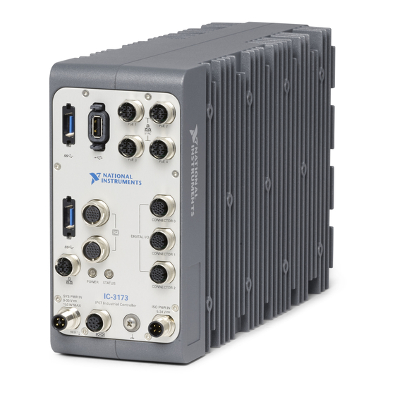
About the IC-3173 (IP67) The IC-3173 (IP67) is a high-performance, small, fanless embedded computer designed for rugged industrial applications. The IC-3173 (IP67) also provides multiple digital input/output (I/O) options for communicating with external devices. IC-317x User Manual | © National Instruments | 27... -
Page 29: Hardware Overview
Figure 23. IC-3173 (IP67) Block Diagram RJ45 Primary Gigabit x2 DisplayPort Ethernet Port Intel Dual-Core Processor i7-5650U, i5-5350U, or Celeron 3765U 8/4 GB DDR3L x2 USB 3.0 Memory Host Ports 64/ 32/4 GB x1 USB 2.0 Solid-state Drive Host Ports Serial Port PCIe RS-232/ 422/ 485... - Page 30 For each DisplayPort connector you use, you must install one ferrite clip, NI part number 711856-01, approximately 25 to 50 mm (1 to 2 in.) from the end of the connector. IC-317x User Manual | © National Instruments | 29...
- Page 31 Figure 25. Installing a Ferrite on the Cable NI recommends the following DisplayPort cable for the IC-3173 (IP67). Cable Part Number 20-position M12 to DisplayPort male cable for IC-3173 (IP67), 3 meters 146858-03 The following figure and table lists the DisplayPort pins and signals. Figure 26.
- Page 32 Power Management tab of the Intel I210 Gigabit Network Connection Properties dialog for the primary Ethernet port in Device Manager. The NI GigE Vision driver (NI-GEV) does not support Wake-on-LAN. The Ethernet ports with PoE do not support Wake-on-LAN. IC-317x User Manual | © National Instruments | 31...
- Page 33 NI recommends the following ethernet cables for the IC-3173 (IP67). Cable Part Number X-Code M12 to X-Code M12 CAT 6A network cable, 5 meters 145231-05 X-Code M12 to RJ45 CAT 6A network cable, 5 meters 145230-05 Figure 27. Ethernet Port Pin Locations (IC-3173 (IP67)) Pin 8 Pin 1 Table 15.
- Page 34 Refer to the following image and table for pin locations and descriptions. Figure 28. 17-pin Digital I/O Connector Pin Locations (IC-3173 (IP67)) Pin 1 Conn 0 Pin 1 Conn 1 Pin 1 Conn 2 IC-317x User Manual | © National Instruments | 33...
- Page 35 Table 16. Digital I/O Connector 0 Pin Descriptions Pin Number Signal Description Iso In 0 Isolated Input No connection Ground for TTL and differential I/O TTL 0 Bidirectional TTL I/O TTL 2 Bidirectional TTL I/O Ground for TTL and differential I/O Iso Out 0 Isolated output Iso Out 1...
- Page 36 Iso Out 7 Isolated output Isolated power voltage reference output Iso In 7 Isolated input No connection No connection Diff 0- Bidirectional RS-422+/Quadrature Encoder A- Diff 1- Bidirectional RS-422+/Quadrature Encoder B- No connection IC-317x User Manual | © National Instruments | 35...
- Page 37 Table 18. Digital I/O Connector 2 Pin Descriptions (Continued) Pin Number Signal Description Common for isolated inputs and outputs Common for isolated inputs and outputs Wiring an Isolated Input You can wire an isolated input to a sourcing output device. Caution Do not apply a voltage greater than 30 VDC to the isolated inputs.
- Page 38 The IC-3173 (IP67) accepts differential (RS-422) line driver inputs. Each of the two differential I/O can be configured as an output. Use shielded cables for all applications. Unshielded cables are more susceptible to noise and can corrupt signals. IC-317x User Manual | © National Instruments | 37...
- Page 39 Figure 31. Quadrature Encoder/RS-422 Input/Output Circuit +3.3 V 10 kΩ 10 kΩ 10 kΩ 10 kΩ Diff I/O 0+ Diff I/O 0– – Diff I/O 1+ – Diff I/O 1– 7.5 kΩ 7.5 kΩ 7.5 kΩ 7.5 kΩ Figure 32. Connecting Differential Line Drivers External Device Industrial Controller Diff In 0+...
- Page 40 Part Number 4-position M12 T-coded pigtail power cable for IC-3173 (IP67), 3 meters 785930-01 4-position M12 T-coded power connector for IC-3173 (IP67) 785928-01 The following figure shows the system power connector. IC-317x User Manual | © National Instruments | 39...
- Page 41 Figure 35. System Power Connector (IC-3173 (IP67)) 1. C 3. C 2. V2 4. V1 Table 19. System Power Connector Terminals Terminal Description System power (9-30 VDC) Common signal System power (9-30 VDC) NI recommends the following accessories for the isolated power input of the IC-3173 (IP67). Cable Part Number 4-position M12 A-coded pigtail ISO power cable for IC-3173 (IP67), 3...
- Page 42 Figure 37. RS-485/422/232 Serial Port Pin Locations (IC-3173 (IP67)) Pin 1 Table 21. RS-485/422/232 Serial Port Pin Descriptions RS-485/422 Mode RS-232 Mode No Connect No Connect Unused Unused Unused Unused Unused Unused IC-317x User Manual | © National Instruments | 41...
- Page 43 USB 3.0 Ports The USB ports support USB peripheral devices such as USB flash drives, USB hard drives, USB-to-IDE adapters, keyboards, mice, and USB cameras. Figure 38. USB 3.0 Port Pin Locations (IC-3173 (IP67)) Table 22. USB 3.0 Port Pin Descriptions Signal Name Signal Description VBUS...
- Page 44 Indication Green Solid The IC-3173 (IP67) is powered from the V1 or V2 input. — The IC-3173 (IP67) is powered off. STATUS LED The following table describes the STATUS LED indications. IC-317x User Manual | © National Instruments | 43...
- Page 45 After the second exception, the IC-3173 (IP67) remains in the exception state, alerting you to resolve the problem. Reinstall software on the IC-3173 (IP67) or contact National Instruments. Continuous This indicates one of the following errors.
-
Page 46: Mounting The Ic-3173 (Ip67)
Refer to the IC-3173 (IP67) Specifications for temperature specifications. To obtain the maximum allowable ambient temperature, you must mount the IC-3173 (IP67) vertically. The following figures provide dimensional drawings and clearance information for the IC-3173 (IP67). IC-317x User Manual | © National Instruments | 45... - Page 47 Figure 40. Front View Dimensions 3.65 in (92.71 mm) 7.59 in (192.77 mm) 2X 6.48 in (164.68 mm) PoE 1 PoE 2 2X 6.02 in (152.97 mm) SYNC 2X 5.58 in (141.82 mm) PoE 4 PoE 3 4.12 in (104.55 mm) 3.82 in (97.11 mm) CONNECTOR 0 3.65 in (92.65 mm)
- Page 48 Allow 50.8 mm (2.0 in.) on the top and bottom of the IC-3173 (IP67) for air circulation. • Allow 50.8 mm (2.0 in.) on the sides of the IC-3173 (IP67) for air circulation. • Allow enough space in front of the IC-3173 (IP67) to connect cables. IC-317x User Manual | © National Instruments | 47...
-
Page 49: Software Options
Figure 42. Clearance Requirements for the IC-3173 (IP67) 2 in (50.8 mm) 2 in (50.8 mm) PoE 1 PoE 2 SYNC PoE 3 PoE 4 CONNECTOR 0 DIGITAL I/O CONNECTOR 1 POWER STATUS CONNECTOR 2 IC-3173 SYS PWR IN 9-30V ISO PWR IN IP67 Industrial Controller 150W MAX... -
Page 50: Ieee 1588 Precision Time Protocol References
Immediately hold down the <Delete> key until the BIOS setup utility appears. The Main setup menu is displayed when you first enter the BIOS setup utility. BIOS Setup Utility Keyboard Navigation Use the following keys to navigate through the BIOS setup utility: IC-317x User Manual | © National Instruments | 49... -
Page 51: Main Setup Menu
Table 26. Navigation Keys Key(s) Function(s) Left Arrow, Right Move between the different setup menus. If you are in a submenu, Arrow these keys have no effect, and you must press <Esc> to leave the submenu first. Up Arrow, Down Move between the options within a setup menu. -
Page 52: Advanced Menu
The default setting is Enabled. • Hardware Prefetcher—This setting specifies whether or not to enable the hardware prefetcher. Enabling this setting may increase performance by prefetching portions of IC-317x User Manual | © National Instruments | 51... - Page 53 memory for the processor, but software jitter may increase. The default setting is Enabled. • Adjacent Cache Prefetcher—This setting specifies whether or not to enable the adjacent cache line prefetcher. Enabling the adjacent cache prefetcher may increase performance by prefetching portions of memory for the processor, but software jitter may increase. The default setting is Enabled.
-
Page 54: Boot Menu
The default value is Disabled. To enable this setting, you must select Enable and then select Save & Exit to restart the device. When this setting is enabled, the Intel IC-317x User Manual | © National Instruments | 53... -
Page 55: Save & Exit Menu
Boot Agent is visible in the Boot Option Priorities menu. This allows you to boot from a PXE server on the local subnet. Note that the Intel Boot Agent device names are preceded by IBA GE Slot in the Boot Option Priorities menu. •... -
Page 56: Restoring The Ni Linux Real-Time Operating System
Insert the USB flash drive into a computer with a DVD drive running Windows, and wait for the flash drive to be recognized. Open a command prompt as an administrator. Type and press <Enter>. diskpart.exe IC-317x User Manual | © National Instruments | 55... - Page 57 Type and press <Enter>. list disk Identify the drive number that corresponds to the USB flash drive. Type , where is the drive number of the USB flash drive, and press select disk <Enter>. For example, in the following image, the USB flash drive is disk number 5. The command is select disk 5 Caution...
-
Page 58: Where To Go Next
Where to Go Next The following documents and resources contain information you may find helpful as you use the IC-317x in an application. Refer to the National Instruments Product Manuals Library at ni.com/manuals for the most recent versions of product documentation. - Page 59 NI trademarks. Other product and company names mentioned herein are trademarks or trade names of their respective companies. For patents covering NI products/technology, refer to the appropriate location: Help»Patents in your software, the file on your media, or the National Instruments Patent Notice at . You can find patents.txt ni.com/patents...
Need help?
Do you have a question about the IC-317 Series and is the answer not in the manual?
Questions and answers