Table of Contents
Advertisement
Quick Links
Advertisement
Table of Contents

Related Manuals for National Instruments RMC-8356


Summary of Contents for National Instruments RMC-8356
- Page 1 RMC-8356 User Manual RMC-8356 User Manual April 2017 376940A-01...
- Page 2 11500 North Mopac Expressway Austin, Texas 78759-3504 USA Tel: 512 683 0100 For further support information, refer to the NI Services appendix. To comment on National Instruments documentation, refer to the National Instruments Web site at ni.com/info enter the Info Code feedback...
- Page 3 National Instruments Corporation. National Instruments respects the intellectual property of others, and we ask our users to do the same. NI software is protected by copyright and other intellectual property laws. Where NI software may be used to reproduce software or other materials belonging to others, you may use NI software only to reproduce materials that you may reproduce in accordance with the terms of any applicable license or other legal restriction.
- Page 4 ™ The ExpressCard word mark and logos are owned by PCMCIA and any use of such marks by National Instruments is under license. The mark LabWindows is used under a license from Microsoft Corporation. Windows is a registered trademark of Microsoft Corporation in the United States and other countries.
- Page 5 Plug the transmitter into a different outlet so that the transmitter and the receiver are on different branch circuits. Furthermore, any modifications to the product not expressly approved by National Instruments could void your authority to operate it under your local regulatory rules.
-
Page 6: Table Of Contents
Contents Chapter 1 Getting Started Unpacking......................... 1-1 What You Need to Get Started ..................1-1 RMC-8356 Overview ....................... 1-2 Key Features ........................1-2 Mainboard Features ....................1-2 CPU ........................1-2 Chipset ......................1-2 Memory ......................1-2 Slots ........................1-3 Video ........................ 1-3 HDD........................ - Page 7 Contents Advanced Setup Configurations ..................2-4 Boot Feature......................2-5 Power Configuration....................2-5 CPU Configuration ....................2-6 CPU Thermal Configuration..................2-9 Chipset Configuration....................2-9 System Agent (SA) Configuration................2-9 Graphics Configuration..................2-10 DMI/OPI Configuration..................2-10 PEG Port Configuration..................2-11 Memory Configuration ..................2-11 GT - Power Management Control ..............
- Page 8 Chapter 3 I/O Information Rear Panel Connectors...................... 3-1 Serial......................... 3-1 SATA........................3-1 Rear I/O ........................3-1 LAN ........................3-1 Universal Serial Bus (USB)................3-2 VGA/DVI Port....................3-3 DP (DisplayPort) ....................3-4 MXI-Express Connectors ....................3-4 © National Instruments | ix...
- Page 9 Contents Chapter 4 Common Configuration Questions General Questions......................4-1 Boot Options ........................4-2 Chassis Configuration....................... 4-2 Upgrade Information......................4-3 Chapter 5 Troubleshooting Appendix A Specifications Appendix B Hardware Configuration Appendix C Intel SATA RAID Utility for Intel C236 Appendix D NI Services Glossary Index...
-
Page 10: Getting Started
Getting Started This chapter describes the key features of the RMC-8356 and lists the kit contents and optional equipment you can order from National Instruments. Unpacking Carefully inspect the shipping container and the RMC-8356 for damage. Check for visible damage to the metal work. Check to make sure all hardware and switches are undamaged. -
Page 11: Rmc-8356 Overview
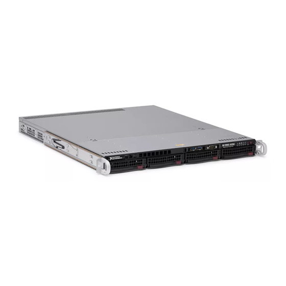
National Instruments. RMC-8356 Overview The RMC-8356 is a 1U PC-based controller for remote control of PXI chassis. The controller provides leading-edge processing power with Intel Xeon E3-1275-V5 processors, high disk bandwidth with RAID support, high I/O bandwidth with a PCI Express 3.0 x16, dedicated Intel Graphics w/ DP, and up to 64 GB of UDIMM Non-ECC memory. -
Page 12: Slots
Internal 4 x 4cm Fans Power Management Features • ACPI/ACPM power management • Main switch override mechanism • Wake-On-LAN (WOL) header • Wake up on keyboard/mouse from Soft-Off • Power-on mode from AC power recovery © National Instruments | 1-3... -
Page 13: Front Panel Leds
+5 V standby alert LED • Fan speed control RMC-8356 Description Figure 1-1 shows the key features of the RMC-8356 front panel. For detailed information about the RMC-8356 rear panel, refer to Chapter 3, Information. Figure 1-1. Front View of the RMC-8356... - Page 14 RMC-8356 User Manual Figure 1-2. Rear View of the RMC-8356 Power Supply Expansion Card Slot I/O Back Panel Rack Ear Brackets The rear of the chassis includes the following features: • Power Supply—350 W Platinum Level Power Supply. • I/O Back Panel—Rear I/O ports.
-
Page 15: Upgrade/Optional Equipment
Upgrade/Optional Equipment Memory Upgrades National Instruments has tested and verified that the DDR-4 UDIMMs and HDDs we offer work with the RMC-8356. We recommend you purchase your DDR-4 UDIMM and HDD modules from National Instruments. Other off-the-shelf DDR-4 UDIMM and HDD modules are not guaranteed to work properly. - Page 16 NI-Sync. For more information, visit ni.com/pxi NI-VISA is the National Instruments implementation of the VISA specification. VISA is a uniform API for communicating and controlling USB, Serial, GPIB, PXI, VXI, and various other types of instruments. This API aids in the creation of portable applications and instrument drivers.
-
Page 17: Installation And Bios Setup
Installation and BIOS Setup This chapter describes how to install, configure, and use the RMC-8356. Read this chapter before connecting the RMC-8356 to a power source. Safety Information Before undertaking any troubleshooting, maintenance, or exploratory Caution procedure, carefully read the following caution notices. -
Page 18: Chassis Cooling Considerations
Air enters through the front of the chassis and exits through the fans on the rear of the chassis. Place the RMC-8356 on a bench top or in an instrument rack so that the fans (air outlets) and the air inlet apertures in the front and rear of the chassis have adequate ventilation. Keep other equipment a minimum of 76.2 mm (3 in.) away from the air outlets on the rear of the chassis. -
Page 19: Connecting Safety Ground
RMC-8356 User Manual Connecting Safety Ground The RMC-8356 is designed with a three-position NEMA 5-15 style plug for the U.S. that connects the ground line to the chassis ground. To minimize shock hazard, make sure the electrical power outlet you use to power the chassis has an appropriate earth safety ground. -
Page 20: Main Setup
Chapter 2 Installation and BIOS Setup The BIOS setup utility uses a key-based navigation system called hot keys. Most of these hot keys (<F1>, <F10>, <Enter>, <ESC>, <Arrow> keys, etc.) can be used at any time during the setup navigation process. Main Setup When you first enter the AMI BIOS setup utility, you will enter the Main setup screen. -
Page 21: Boot Feature
4_Seconds_Override for the user to power off the system after pressing and holding the power button for 4 seconds or longer. Select Instant Off to instantly power off the system as soon as the user presses the power button. The options are 4 Seconds Override and Instant Off. © National Instruments | 2-5... -
Page 22: Cpu Configuration
Chapter 2 Installation and BIOS Setup Restore on AC Power Loss Use this feature to set the power state after a power outage. Select Stay-Off for the system power to remain off after a power loss. Select Power-On for the system power to be turned on after a power loss. - Page 23 Select Enabled for processor cores to run faster than the frequency specified by the manufacturer. The options are Disabled and Enabled. Package Power Limit MSR Lock Select Enabled to lock the package power limit for the model specific registers. The options are Disabled and Enabled. © National Instruments | 2-7...
- Page 24 Chapter 2 Installation and BIOS Setup Power Limit 1 Override Select Enabled to support average power limit (PL1) override. The default setting is Disabled. Power Limit 2 Override Select Enabled to support rapid power limit (PL2) override. The default setting is Enabled. Power Limit 2 Use this item to configure the value for Power Limit 2.
-
Page 25: Cpu Thermal Configuration
Setting the wrong values in the following features may cause the system Caution to malfunction. System Agent (SA) Configuration The following System Agent information will display: • System Agent Bridge Name • SA PCIe Code Version • VT-d © National Instruments | 2-9... -
Page 26: Graphics Configuration
Chapter 2 Installation and BIOS Setup VT-d Select Enabled to enable Intel Virtualization Technology support for Direct I/O VT-d by reporting the I/O device assignments to VMM through the DMAR ACPI Tables. This feature offers fully-protected I/O resource-sharing across the Intel platforms, providing the user with greater reliability, security and availability in networking and data-sharing. -
Page 27: Peg Port Configuration
OPROM. If this item is set to Disabled, the PCI-E ASPM will be programmed before OPROM. The options are Disabled and Enabled. Memory Configuration The following memory information will display: • Memory RC Version • Memory Frequency • Total Memory © National Instruments | 2-11... -
Page 28: Gt - Power Management Control
Chapter 2 Installation and BIOS Setup • • DIMMA1 • DIMMA2 • DIMMB1 • DIMMB2 • Memory Timings (tCL-tRCD-tRP-tRAS) Maximum Memory Frequency Use this feature to set the maximum memory frequency for onboard memory modules. The options are Auto, 1067, 1200, 1333, 1400, 1600, 1800, 1867, 2000, 2133, 2200, 2400, 2600, 2667, 2800, 2933, 3000, and 3200. -
Page 29: Pch-Io Configuration
Use this item to set the Active State Power Management (ASPM) level for a PCI-E device. Select Auto for the system BIOS to automatically set the ASPM level based on the system configuration. Select Disabled to disable ASPM support. The options are Disabled, L0s, L1, L0s & L1, and Auto. © National Instruments | 2-13... -
Page 30: Sata Configuration
Chapter 2 Installation and BIOS Setup SLOT7 L1 Substates Use this feature to set the PCI Express L1 Substates. The options are Disabled, L1.1, L1.2, and L1.1 & L1.2 SLOT7 PCIe Speed Use this feature to select the PCI Express port speed. The options are Auto, Gen1, Gen2, and Gen3. -
Page 31: Pcie/Pci/Pnp Configuration
The options are Disabled, Legacy, and EFI. PCH SLOT 7 PCI-E 3.0 X4 (IN X8) Use this feature to select which firmware type to be loaded for the add-on card in this slot. The options are Disabled, Legacy, and EFI. © National Instruments | 2-15... - Page 32 Chapter 2 Installation and BIOS Setup Onboard LAN Option ROM Type Select Enabled to enable Option ROM support to boot the computer using a network device specified by the user. The options are Legacy and EFI. Onboard LAN1 Option ROM Use this option to select the type of device installed in LAN Port1 used for system boot.
-
Page 33: Super Io Configuration
This feature specifies the base I/O port address and the Interrupt Request address of a serial port specified by the user. Select Auto to allow the BIOS to automatically assign the base I/O and IRQ address. © National Instruments | 2-17... -
Page 34: Pch-Fw Configuration
Chapter 2 Installation and BIOS Setup The options for Serial Port 2 are Use Automatic Settings, (IO=2F8h; IRQ=3; DMA), (IO=3F8h; IRQ=3, 4, 5, 6, 7, 9, 10, 11, 12; DMA), (IO=2F8h; IRQ=3, 4, 5, 6, 7, 9, 10, 11, 12; DMA), (IO=3E8h;... -
Page 35: Serial Port Console Redirection
A stop bit indicates the end of a serial data packet. Select 1 Stop Bit for standard serial data communication. Select 2 Stop Bits if slower devices are used. The options are 1 and 2. © National Instruments | 2-19... - Page 36 Chapter 2 Installation and BIOS Setup COM1 Flow Control Use this feature to set the flow control for Console Redirection to prevent data loss caused by buffer overflow. Send a Stop signal to stop sending data when the receiving buffer is full. Send a Start signal to start sending data when the receiving buffer is empty.
-
Page 37: Sol/Com2 Console Redirection Settings
Send a Stop signal to stop sending data when the receiving buffer is full. Send a Start signal to start sending data when the receiving buffer is empty. The options are None and Hardware RTS/CTS. © National Instruments | 2-21... -
Page 38: Com2 Legacy Os Redirection Resolution
Chapter 2 Installation and BIOS Setup COM2 VT-UTF8 Combo Key Support Select Enabled to enable VT-UTF8 Combination Key support for ANSI/VT100 terminals. The options are Disabled and Enabled. COM2 Recorder Mode Select Enabled to capture the data displayed on a terminal and send it as text messages to a remote server. -
Page 39: Acpi Settings
Select Enabled to support the Windows Hardware Error Architecture (WHEA) platform and provide a common infrastructure for the system to handle hardware errors within the Windows OS environment to reduce system crashes and to enhance system recovery and health monitoring. The options are Enabled and Disabled. © National Instruments | 2-23... -
Page 40: Trusted Computing Configuration
Chapter 2 Installation and BIOS Setup Trusted Computing Configuration Security Device Support If this feature and the TPM jumper on the motherboard are both set to Enabled, onboard security devices will be enabled for TPM (Trusted Platform Module) support to enhance data integrity and network security. -
Page 41: Intel I210 Gigabit Network Connection - 00:25:90:5D:39:Af
This item displays the PCI address for this computer. PCI addresses are 3 two-digit hexadecimal numbers. Link Status This item displays the connection status. MAC Address This item displays the MAC address for this computer. Mac addresses are 6 two-digit hexadecimal numbers. © National Instruments | 2-25... -
Page 42: Intel Ethernet Connection (H) I219-Lm 00:25:90:5D:39:Ae
Chapter 2 Installation and BIOS Setup Intel Ethernet Connection (H) I219-LM 00:25:90:5D:39:AE NIC Configuration Link Speed Use this feature to specify the port speed used for the selected boot protocol. The options are Auto Negotiated, 10 Mbps Half, 10 Mbps Full, 100 Mbps Half, and 100 Mbps Full. Wake On LAN Select Enabled for Wake_On_LAN support, which will allow the system to wake up when an onboard LAN device receives an incoming signal. -
Page 43: Event Logs
MECI is incremented. This is in minutes, from 0 to 99. The default value is 60. After making changes on a setting, be sure to reboot the system for the Note changes to take effect. © National Instruments | 2-27... -
Page 44: View Smbios Event Log
Chapter 2 Installation and BIOS Setup View SMBIOS Event Log This section displays the contents of the SMBIOS Event Log. IPMI Use this feature to configure Intelligent Platform Management Interface (IPMI) settings. BMC Firmware Revision This item indicates the IPMI firmware revision used in your system. IPMI Status (Baseboard Management Controller) This item indicates the status of the IPMI firmware installed in your system. -
Page 45: Ipmi Network Link Status
Update Manager (SUM) or extended IPMI features. The BMC network configuration in the BIOS setup is also invalid when IPMI Function Support is disabled. The general BMC function and motherboard health monitor such as fan control are still functioning when this option is disabled. © National Instruments | 2-29... -
Page 46: Security
Chapter 2 Installation and BIOS Setup Security This menu allows the user to configure the following security settings for the system. Password Check Select Setup for the system to check for a password at Setup. Select Always for the system to check for a password at bootup or upon entering the BIOS Setup utility. - Page 47 The options are Yes and No. Append Key Select Yes to add the DBT from the manufacturer's defaults list to the existing DBT. Select No to load the DBT from a file. The options are Yes and No. © National Instruments | 2-31...
-
Page 48: Boot
Chapter 2 Installation and BIOS Setup Boot Use this feature to configure Boot Settings: Boot Mode Select Use this item to select the type of device that the system is going to boot from. The options are Legacy, UEFI, and Dual. The default setting is Dual. Fixed Boot Order Priorities This option prioritizes the order of bootable devices that the system to boot from. -
Page 49: Save & Exit
Save As User Defaults To set this feature, select Save as User Defaults from the Exit menu and press <Enter>. This enables the user to save any changes to the BIOS setup for future use. © National Instruments | 2-33... -
Page 50: Bios Error Beep Codes
USB erases the contents of your hard disk. Before recovering the OS, back up any files you want to keep. The RMC-8356 includes a preinstalled OS from the factory. The RMC-8356 also includes two methods of restoring/reinstalling the OS to your system. -
Page 51: Cleaning
Note • The RMC-8356 may also ship with an OS recovery USB you can use to reinstall your operating system onto your hard drive. If you need to reinstall your operating system, you can use the included OS recovery USB. -
Page 52: Rack Mounting
Chapter 2 Installation and BIOS Setup Rack Mounting When mounting the equipment in the rack, do not create a hazardous Caution condition due to uneven mechanical loading. Installing the Rails There are a variety of rack units on the market, which may require a slightly different assembly procedure. -
Page 53: Installing The Rack Rails
Line up the rear of the chassis rails with the front of the rack rails. Slide the chassis rails into the rack rails, keeping the pressure even on both sides (you may have to press the locking tabs when inserting). © National Instruments | 2-37... -
Page 54: Installing The Server Into A Telco Rack
Chapter 2 Installation and BIOS Setup When the server has been pushed completely into the rack, you should hear the locking tabs click. Figure 2-2. Installing the Server into a Rack Figures are for illustrative purposes only. Always install servers to the bottom Note of a rack first. - Page 55 Finish by sliding the chassis into the rack and tightening the brackets to the rack. Figure 2-3. Installing the Server into a Telco Rack Figure is for illustrative purposes only. Always install servers to the bottom Note of a rack first. © National Instruments | 2-39...
-
Page 56: I/O Information
I/O Information This chapter describes the RMC-8356 I/O connectors. Rear Panel Connectors Serial Two COM connectors (COM1 & COM2) are provided on the motherboard. Both are located near the PCI-E slot 4. SATA The motherboard includes a total of four SATA connectors, supported by the Intel C236 PCH chip. -
Page 57: Universal Serial Bus (Usb)
Chapter 3 I/O Information Universal Serial Bus (USB) There are two USB 2.0 connectors (USB0/1) and two USB 3.0 connectors (USB2/3) located on the I/O back panel. The motherboard also has three front access USB 2.0 headers (USB4/5, USB6/7, and USB8/9) and one front access USB 3.0 header (USB10/11). The USB12 header is USB Type A. -
Page 58: Vga/Dvi Port
A VGA connector and a DVI connector are located next to the LAN connector on the I/O back panel. Use these connections for VGA and DVI displays. The VGA connector is on top and the DVI is on the bottom. © National Instruments | 3-3... -
Page 59: Dp (Displayport)
Chapter 3 I/O Information DP (DisplayPort) There are two DisplayPort connectors located on the rear I/O back panel. DisplayPort, developed by the VESA consortium, delivers digital display at a fast refresh rate. It can connect to virtually any display using a DisplayPort adapter for devices such as VGA, DVI, or HDMI. MXI-Express Connectors Refer to your MXI-Express hardware user manual for connector information. -
Page 60: Common Configuration Questions
Does the RMC-8356 support a PCI card? No, the RMC-8356 can support only PCI Express cards while using a riser card (provided). What is the shortcut key to get to the boot menu while the BIOS is going through POST? The shortcut key is <F11>. -
Page 61: Boot Options
Setup, for more information. Chassis Configuration How do I set up the RMC-8356 to work with my PXI chassis? Configuration of the PXI system is handled through Measurement & Automation Explorer (MAX), included with the software pre-installed on your RMC-8356. MAX creates the pxi- file, which defines the layout and parameters of your PXI system. -
Page 62: Upgrade Information
Where do I get the latest software drivers? The latest National Instruments software is available from ni.com/downloads What upgrade options are available for the RMC-8356? Table 4-1 lists the available upgrade options. Table 4-1. RMC-8356 Upgrade Options Orderable P/N... -
Page 63: Troubleshooting
Chapter 2, Installation and BIOS Setup.) My RMC-8356 boots fine until I get to Windows, at which point I cannot read the screen. This may include garbled output, white screen, black screen, or an out of synch message from the monitor. - Page 64 Chapter 5 Troubleshooting tings. Try setting the resolution to 640 × 480 and the refresh rate to 60 Hz. Once you reboot, you can raise these values again, using the test option in Windows. These settings are accessible through the Advanced tab of the Display item in the Control Panel. Alternately, you can try a different monitor, preferably a newer and larger one.
-
Page 65: Appendix A Specifications
The AC power cable provides main power disconnect. Depressing the front panel power switch enables or inhibits the internal power supply. Using the RMC-8356 in a manner not described in this document may Caution impair the protection the RMC-8356 provides. Mainboard... - Page 66 Appendix A Specifications Video 2 x Display Port 1 x DVI-I 1 x VGA (disabled by default) Serial RS-232 serial port 2 x Gigabit Ethernet RJ45, 1 x Dedicated IPMI RJ45 Onboard LAN controller Intel i219LM + i210AT Dual-Port Gigabit Ethernet controller Xeon E3-1275-V5 Clock speed...
- Page 67 Minimum 53.1 dBA Maximum 61.4 dBA Safety This product is designed to meet the requirements of the following standards of safety for information technology equipment: • IEC 60950-1, EN 60950-1 • UL 60950-1, CSA 60950-1 © National Instruments | A-3...
- Page 68 Appendix A Specifications Overloading the circuits may damage supply wiring. Do not exceed the Caution ratings on the equipment nameplate when connecting equipment to the supply circuit. For UL and other safety certifications, refer to the product label or the Online Note Product Certification...
- Page 69 At the end of the product life cycle, all products must be sent to a EU Customers WEEE recycling center. For more information about WEEE recycling centers, National Instruments WEEE initiatives, and compliance with WEEE Directive 2012/19/EC on Waste and Electronic Equipment, visit ni.com/environment/weee Battery Replacement and Disposal This device contains a long-life coin cell battery.
- Page 70 Disconnect the power cord before servicing. Motherboard Layout The following is a layout of the RMC-8356 motherboard with jumper, connector, and LED locations shown. Refer the following tables for descriptions. For detailed descriptions, pinout information and jumper settings, refer to the Power Connections section.
- Page 71 Appendix B Hardware Configuration Figure B-1. RMC-8356 Mainboard Layout LED1 DP1/DP2 USB2/3(3.0) VGA/DVI IPMI_LAN LAN1/2 LED2 USB0/1 LED3 LAN3/4 JPW2 JPL3 COM1 JPL2 JPL1 FAN4 JPW1 MAC CODE COM2 MAC CODE USB8/9 USB6/7 USB4/5 I-SATA3 JBT1 BIOS LICENSE JPI2C1 I-SATA1...
- Page 72 Failure to do so voids the manufacturer warranty on your power supply and motherboard. When the LED4 LED is on, the onboard power connection is on. Be sure to Note unplug the power cables before removing or installing components. © National Instruments | B-3...
- Page 73 Appendix B Hardware Configuration Table B-2. Connector Descriptions Connector Description AUDIO FP Audio Front Panel Header Onboard Battery COM1/COM2 COM Headers DP1/DP2 DisplayPorts FAN1 ~ FAN4 System/CPU Fan Headers FANA, FANB I/O Fan Headers IPMI_LAN Dedicated IPMI LAN Port ® I-SATA0 ~ I-SATA3 Intel PCH SATA 3.0 Ports...
- Page 74 All JF1 wires have been bundled into a single cable to simplify this connection. Make sure the red wire plugs into pin 1 as marked on the motherboard. The other end connects to the control panel PCB board. © National Instruments | B-5...
- Page 75 Appendix B Hardware Configuration Figure B-2. JF1 Header Pins Ground 3.3V Stby FP PWRLED HDD LED 3.3V Stby NIC1 Link LED NIC1 Activity LED NIC2 Activity LED NIC2 Link LED UID LED Blue Cathode OH/Fan Fail LED 3.3V Power Fail LED Reset Reset Button Ground...
- Page 76 Processor Power Connector The 8-pin JPW2 must also be connected to the power supply. This connector is used to power the processor(s). Table B-5. +12 V 8-Pin Power Pin Definitions Definition Ground +12 V Required Connection © National Instruments | B-7...
- Page 77 Appendix B Hardware Configuration 4-pin 12 V Power Connector JPWR1 is a 4-pin 12 V power connector that provides alternative power. Table B-6. 4-Pin Power Pin Definitions Definition Ground +12 V Extended CMOS Battery Connector J18 is a secondary power connector that provides power to the CMOS battery. Table B-7.
- Page 78 SGPIO Headers The I-SGPIO1 (Serial General Purpose Input/Output) header is used to communicate with the enclosure management chip on the backplane. Table B-11. SGPIO Header Pin Definitions Definition Definition Data Load Clock NC = No Connection © National Instruments | B-9...
- Page 79 Appendix B Hardware Configuration General Purpose I/O Header The JGPIO1 (General Purpose Input/Output) header is a general purpose I/O expander on a pin header via the SMBus. Table B-12. JGPIO1 Header Pin Definitions Definition Definition 3.3 V Stby TPM/Port 80 Header A Trusted Platform Module (TPM)/Port 80 header is located at JTPM1 to provide TPM support and Port 80 connection.
- Page 80 A Chassis Intrusion header is located at JL1 on the motherboard. Attach the appropriate cable from the chassis to the header to inform you when the chassis has been opened. Table B-16. Chassis Intrusion Pin Definitions Definition Intrusion Input Ground © National Instruments | B-11...
- Page 81 Appendix B Hardware Configuration Internal Speaker/Buzzer The Internal Speaker/Buzzer (SP1) is used to provide audible indications for various beep codes. Table B-17. Internal Buzzer Pin Definitions Definition Pos (+) Beep In Neg (-) Alarm Speaker Power SMB (I C) Header Power System Management Bus (I C) header at JPI C1 monitors the power supply, fan and...
- Page 82 UID can also be triggered via IPMI on the motherboard. Note Table B-22. UID Switch Pin Definitions Definition Ground Ground Button In Button In © National Instruments | B-13...
- Page 83 Appendix B Hardware Configuration Table B-23. UID LED Pin Definitions Color Status Blue: On Unit Identified Pin Definitions Power Button The Power Button connection is located on pins 1 and 2 of JF1. Momentarily contacting both pins will power on/off the system. This button can also be configured to function as a suspend button.
- Page 84 Table B-29. HDD LED Pin Definitions (JF1) Definition 3.3 V Stby HD Active Power LED The Power LED connection is located on pins 15 and 16 of JF1. Table B-30. Power LED Pin Definitions (JF1) Definition 3.3 V Standby Power LED © National Instruments | B-15...
- Page 85 Appendix B Hardware Configuration NMI Button The non-maskable interrupt button header is located on pins 19 and 20 of JF1. Table B-31. NMI Button Pin Definitions (JF1) Definition Control Ground Jumpers To modify the operation of the motherboard, jumpers are used to choose between optional settings.
- Page 86 IPMI connection. This jumper is used together with the IPMI settings in the BIOS. If the BMC is disabled, IPMI health monitoring and remote management functions are no longer supported. The default setting is BMC Enable. © National Instruments | B-17...
- Page 87 Appendix B Hardware Configuration Table B-35. BMC Enabled Jumper Settings Jumper Setting Definition Pins 1-2 BMC Enabled Pins 2-3 Disabled Manufacturer Mode Select Close pins 2 and 3 of jumper JPME2 to bypass SPI flash security and force the system to operate in the manufacturer mode, which will allow the user to flash the system firmware from a host server for system setting modifications.
- Page 88 Be sure to turn off the system and unplug the power cord before removing or installing components. Table B-42. Onboard Power LED Indicator LED Color Definition System Off (power cable not connected) Green System On © National Instruments | B-19...
- Page 89 Appendix B Hardware Configuration Overheat/PWR Fail/Fan Fail LED An Overheat/PWR/Fail/ Fan Fail LED is located at LED2. Table B-43. Overheat/PWR Fail/Fan Fail LED Indicator) LED Color Definition Solid Overheat Blinking PWR Fail or Fan Fail Data Cables The data cables in the system have been carefully routed to maintain airflow efficiency. If you disconnect any data cables, take care to re-route them as they were originally when reconnecting them.
- Page 90 Also, note that the memory is interleaved to improve performance. Memory Support The RMC-8356 supports up to 64 GB registered UDIMM ECC DDR4 2133 MHz in 4 DIMMs. (Refer to for the recommended memory list.) ni.com System Memory Allocation and Availability Table B-44 lists possible system memory allocation and availability.
- Page 91 Memory available for the OS and other — 2.84 GB applications Installing DDR Modules Follow these steps to install DDR modules: Remove power from system. Press the cover release buttons on the top of the RMC-8356. Push the cover backward to remove it. B-22 | ni.com...
- Page 92 Notch When the module is fully inserted, the plastic clip at each side of the slot automatically closes, as shown below. Replace the RMC-8356 cover by sliding the cover forward. Make sure the safety lock fits firmly. Removing DDR Modules Follow these steps to remove DDR modules: Remove power from system.
- Page 93 Appendix B Hardware Configuration Upgrading and Replacing Hard Disk Drives Hard Drives Your server may or may not have come with hard drives installed. Up to four 3.5" hard drives are supported by the chassis. The SATA drives are mounted in drive carriers to simplify their installation and removal from the chassis.
- Page 94 See the table below for details. Table B-45. Hard Drive Carrier LED Indicators State/Condition Indication Green Blinking Drive activity Solid on Drive failure Enterprise level hard disk drives are recommended for use in NI chassis and Note servers. © National Instruments | B-25...
- Page 95 Part Number Description 785651-01 Spare 1 TB HDD for RMC-8356 PCI Expansion Card Installation The system includes a pre-installed riser card that positions a standard size PCI-E x16 card at a 90 degree angle, allowing it to fit inside the chassis.
- Page 96 Connect the fan wires to the same fan header as the fan just removed. Plug the power cord into the rear of the power supply, power up the system and check that the fan is working properly before replacing the chassis cover. © National Instruments | B-27...
- Page 97 In the Advanced menu, scroll down to IDE/SATA Configuration and press <Enter> to enter the IDE/SATA Configuration submenu. Once in the IDE/SATA Configuration submenu, scroll down to Configure SATA#1 as and press <Enter>. The Options window displays. From the Options window, select RAID and press <Enter>. © National Instruments | C-1...
- Page 98 Appendix C Intel SATA RAID Utility for Intel C236 Press <Esc> to return to the previous menu. Use the arrow keys to select Exit from the menu bar at the top and press <Enter> to enter the Exit submenu. From the Exit submenu, select Save Changes and Exit and press <Enter> to save the changes and exit the BIOS.
- Page 99 At the prompt, press Are you sure you want to create this volume (Y/N) <Y> to create the RAID volume or <N> to return to the Create Volume menu without making changes. © National Instruments | C-3...
- Page 100 Appendix C Intel SATA RAID Utility for Intel C236 Deleting a RAID Volume Be sure to back up your data before deleting a RAID set. You will lose all Caution data on the drives when deleting a RAID set. You also will lose the recovery image. Follow these steps to delete a RAID volume: From the main menu, select Delete RAID Volume and press <Enter>.
- Page 101 Press <Esc> to return to the Main menu. Exiting the Intel RSTe SATA Controller Follow these steps to exit the Intel RSTe SATA Controller: Press <ESC> to return to the Advanced menu. Press <F4> to save changes and restart the system. © National Instruments | C-5...
- Page 102 • System Integration—If you have time constraints, limited in-house technical resources, or other project challenges, National Instruments Alliance Partner members can help. To learn more, call your local NI office or visit ni.com/alliance • Training and Certification—The NI training and certification program is the most effective way to increase application development proficiency and productivity.
- Page 103 Appendix D NI Services your time and budget constraints and personal learning preferences. Visit ni.com/ to see these custom paths. skills-guide – NI offers courses in several languages and formats including instructor-led classes at facilities worldwide, courses on-site at your facility, and online courses to serve your individual needs.
- Page 104 ACPI Advanced Configuration and Power Management Interface ANSI American National Standards Institute Application Programming Interface—A standardized set of subroutines or functions along with the parameters that a program can call. APIC Advanced Programmable Interrupt Controller © National Instruments | G-1...
- Page 105 Glossary ASCII American Standard Code for Information Exchange ASIC Application-Specific Integrated Circuit The specification formulated in the 1980s that defines the IDE drive interface. Bytes BIOS Basic Input/Output System—BIOS functions are the fundamental level of any PC or compatible computer. BIOS functions embody the basic operations needed for successful use of the computer’s hardware resources.
- Page 106 Intel Pentium. EEPROM Electronically Erasable Programmable Read Only Memory Electromagnetic Compatibility Electromagnetic Interference Enhanced Parallel Port Federal Communications Commission Gigabytes of memory GPIB General Purpose Interface Bus (IEEE 488) Hard Disk Drive Hertz; cycles per second © National Instruments | G-3...
- Page 107 Glossary Input/output—The techniques, media, and devices used to achieve communication between machines and users. Integrated Drive Electronics—Hard disk and built-in controller. IEEE Institute of Electrical and Electronics Engineers IRQ* Interrupt signal Industry Standard Architecture—The original PC bus architecture, specifically the 16-bit AT bus. Kilobytes of memory Local Area Network—Communications network that serves users within a confined geographical area.
- Page 108 RMC-8356 User Manual NI-DAQ The National Instruments software for data acquisition instruments. NI-VISA The National Instruments implementation of the VISA standard—An interface-independent software that provides a unified programming interface for VXI, GPIB, and serial instruments. Peripheral Component Interconnect. The PCI bus is a high-performance 32-bit or 64-bit bus with multiplexed address and data lines.
- Page 109 Glossary SATA Serial-ATA. See also ATA. SCSI Small Computer System Inteface SDRAM A form of dynamic RAM memory that is about 20% faster than EDO RAM. SDRAM interleaves two or more internal memory arrays so that while one array is being accessed, the next one is being prepared for access.
- Page 110 RMC-8356 User Manual Watts Watchdog Timer © National Instruments | G-7...
- Page 111 4-2 creating volumes general questions, 4-1 RAID0, C-2 upgrade information, 4-3 RAID1, C-2 cooling, air cooling of RMC-8356, 2-2 deleting a RAID volume, C-4 exiting Intel Matrix Storage Manager utility, C-5 Intel HostRAID configurations, C-1 DDR DIMMs recovery volume options, C-4...
- Page 112 RAID volume, deleting, C-4 See also drivers RAID0 volume, creating, C-2 LabVIEW, 1-6 RAID1 volume, creating, C-2 LabWindows/CVI, 1-6 Measurement Studio, 1-6 DDR DIMMs from National Instruments National Instruments software, 1-6 (note), 1-6 NI-DAQmx, 1-6 upgrading, 4-3 NI-VISA, 1-7 recovery volume...
- Page 113 A-3 testing power up, 2-3 troubleshooting controller does not boot, 5-1 damaged module, 5-2 video display, 5-1 unpacking the RMC-8356, 1-1 upgrade equipment, 1-6 upgrading hard disk drives, B-24 upgrading memory, B-20 installing DDR modules, B-22 removing DDR modules, B-23...
Need help?
Do you have a question about the RMC-8356 and is the answer not in the manual?
Questions and answers