Table of Contents
Advertisement
Quick Links
Download this manual
See also:
Installation Manual
General Installation Manual
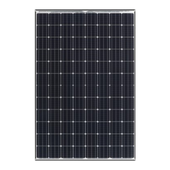
Photovoltaic Module HIT
VBHNxxxSJ25 series
VBHNxxxSJ45 series
VBHNxxxSJ47 series
Model No.
VBHN240SJ25, VBHN245SJ25,
VBHN294SJ45,
VBHN320SJ47, VBHN325SJ47, VBHN330SJ47
VBHNxxxSJ25 series
Thank you for choosing Panasonic photovoltaic module HIT
Please read this manual completely before you install or use of
TM
HIT
. With proper operation and maintenance, HIT
provide you with clean, renewable solar electricity for many
years. This manual contains important installation, mainte-
nance and safety information. The word "module" as used in
this manual refers to one or more PV modules. Retain this
manual for future reference.
VBHNxxxSJ45 series
TM
VBHNxxxSJ47 series
TM
.
TM
will
CONTENTS
・GENERAL INFORMATION
・SPECIAL CONDITIONS
"HIT" is a trademark of the Panasonic Group.
Other product and service names listed in this
manual are trademarks or registered trademarks
of respective companies.
2
3
7
8
9
11
12
13
Advertisement
Table of Contents

Related Manuals for Panasonic VBHNxxxSJ25 series


Summary of Contents for Panasonic VBHNxxxSJ25 series
-
Page 1: Table Of Contents
VBHNxxxSJ45 series DISCLAIMER OF LIABILITY CUSTOMER SERVICES Thank you for choosing Panasonic photovoltaic module HIT “HIT” is a trademark of the Panasonic Group. Please read this manual completely before you install or use of Other product and service names listed in this . -
Page 2: Safety Precautions
vices such as ground fault, fuses, Do not puncture or damage the installed by Panasonic. There are no and disconnects may be required. back sheet of a module. Do not use user serviceable parts within the the PV module and make a replace- ... -
Page 3: Module Specifications
MODULE SPECIFICATIONS Test Conditions (STC). Irradiance of multiplied by a factor of 1.25 when 1000W/m , 25±2℃ cell tempera- determining voltage ratings, con- Module specifications are shown in ture, AM1.5 and solar spectral irradi- ductor capacities, fuse sizes, and Table 1-1, 1-2, 1-3 and Figure 1-1, 1- ance according to IEC 60904-3. - Page 4 Dimension in mm Back side * The positions of the holes are all symmetrical against the center of the module. Section A-A’ Section B-B’ Side Front side Note) A module is installed using 4 points, symmetrical mounting within setting range (shaded). Figure 1-1.
- Page 5 Table 1-2. Model Specifications Model VBHN294SJ45 Maximum Power (Pmax) +10/-0 % Open Circuit Voltage (Voc) ±10 % 63.7 Short Circuit Voltage (Isc) ≧90 % 5.99 Maximum Power Voltage (Vpm) 52.6 Maximum Power Current (Ipm) 5.59 Cell Number in Series Cell Type Silicon hetero-junction* Maximum System Voltage (Vsys) 1000...
- Page 6 Table 1-3. Model Specifications Model VBHN320SJ47 VBHN325SJ47 VBHN330SJ47 Maximum Power (Pmax) +10/-0 % Open Circuit Voltage (Voc) ±10 % 69.4 69.6 69.7 Short Circuit Voltage (Isc) ≧90 % 5.98 6.03 6.07 Maximum Power Voltage (Vpm) 57.3 57.6 58.0 Maximum Power Current (Ipm) 5.59 5.65 5.70...
-
Page 7: Standards
STANDARDS tion box contain terminals for both any other additional bypass diodes. positive and negative polarity, and Specifications of bypass diode for VBHNxxxSJ series comply with the re- bypass diodes. VBHNxxxSJ25 modules are as fol- quirements of IEC61215, IEC61730-1, ... -
Page 8: Installation
Conditions. An installation location with conditions beyond the Operating Condi- tions or with other Special Conditions (see below) should be avoided. Operat- ing Conditions of Panasonic modules are as follows: Figure 4. Fixing of cables 1) The modules should be operated only and connectors in terrestrial applications. -
Page 9: Module Installation
Panasonic recom- mends to install panels at a slope Clearance 100mm between the roof Please contact your Panasonic Au- steeper than the water gradient. surface and module frame is re- thorized Representative with ques- quired to allow cooling air to circu-... - Page 10 Installation (reference) 38mm 34mm Solar Module Metal clamp B 38mm (2 places) 46mm Metal clamp A (2 places) Mounting Structure Rail For VBHNxxxSJ45 38mm 11mm Solar Module Metal clamp B 38mm (2 places) 35mm Metal clamp A (2 places) Mounting Structure Rail For VBHNxxxSJ47 Solar Module...
-
Page 11: Wiring
PV module caused by age devices. In particular, as the lightning. Please contact your Panasonic Au- temperature characteristic of the PV thorized Representative with ques- module, the voltage value rises on... -
Page 12: Maintenance
MAINTENANCE strong alkaline detergent, strong The return of any modules will not be acid detergent or a detergent which accepted by Panasonic unless prior writ- In order to maintain the optimum forms a protective layer on the sur- ten authorization has been given by... -
Page 13: Customer Services
Tel: +84-8-3813-4591 Fax: +84-8-3813-4595 © SANYO Electric Co., Ltd. 2018 Panasonic Manufacturing Philippines Corporation SANYO is part of the Panasonic Group and is in charge of the manufacturing process for HIT Tel: +63-2-886-6291 IM001-0918-2 Fax: +63-2-886-6295 Panasonic Eco Solutions Sales (Thailand) Co., Ltd.