
Related Manuals for Steca PR 1010


Summary of Contents for Steca PR 1010
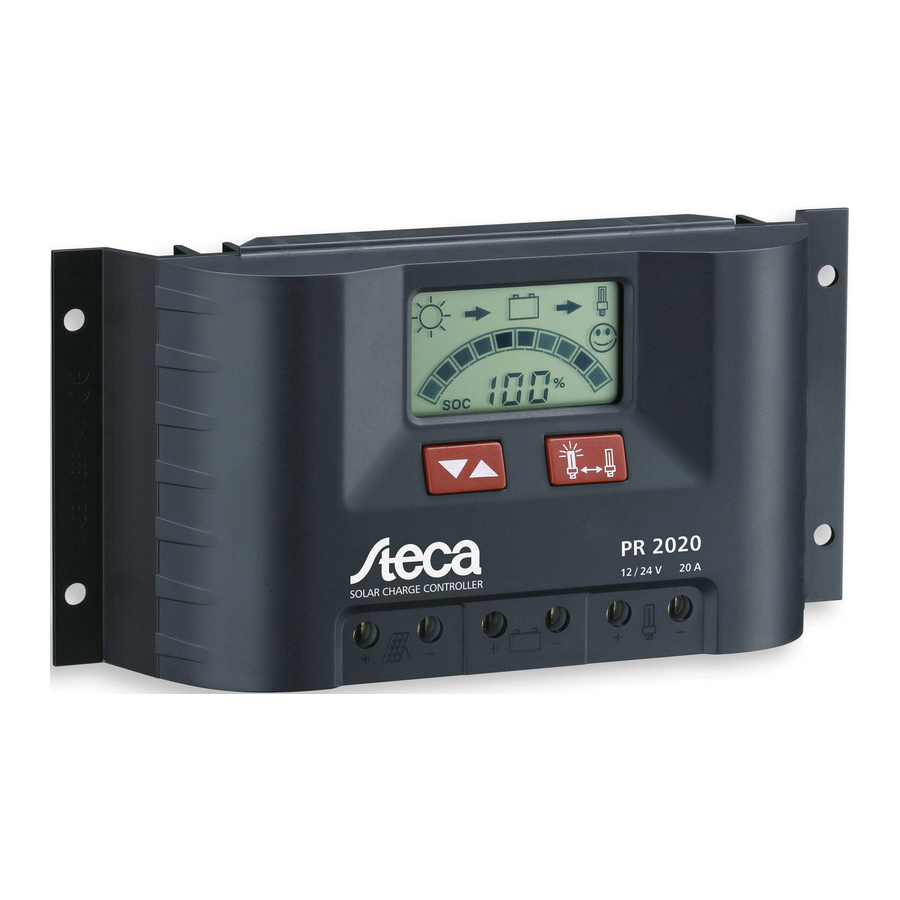
- Page 1 Operating instructions Solar charge controller 10 A / 15 A / 20 A / 30 A 739.704 | 11.10...
-
Page 2: Table Of Contents
Contents Safety instructions Safety instructions are identified as follows General safety instructions Exclusion of liability Area of application Controller protection functions Installation Mounting location Connecting the controller Grounding Operation Display and control elements Display windows 6.2.1 SOC window 6.2.2 Voltage window 6.2.3 Module current 6.2.4 Charging current 6.2.5 Load current... -
Page 3: Safety Instructions
Safety instructions 1.1 Safety instructions are identified as follows In this manual, safety instructions for personal safety are identified with this symbol. Instructions relating to the functional safety of the system and the controller are in bold type. 1.2 General safety instructions Be sure to observe the following instructions when installing the controller and handling the batteries: Incorrect handling of batteries results in a danger of explosion! -
Page 4: Area Of Application
Area of application These instructions describe the functions and installation of a charge controller for photovoltaic (PV) systems to be used for charging 12 V or 24 V lead-acid batteries in the hobby and leisure, residential, business, com- mercial and small company areas. The charge controller is only suitable for controlling solar modules. -
Page 5: Installation
• Overvoltage and undervoltage protection Immediately switches off the load output in the case of excessively high or low battery voltage. • Overtemperature protection If the temperature inside the controller becomes too high, then the controller load output is switched off to reduce the power loss. • Load output overload protection If the permissible load current is exceeded, then the load output is switched off. -
Page 6: Connecting The Controller
5.2 Connecting the controller Solar modules generate electricity under incident light. The full voltage is present, even when the incident light levels are low. You should therefore work carefully and avoid creating sparks. Observe the appropriate safety precautions. Double the normal system voltages can be present during installation and electrical connection of the DC side of the photovoltaic system (up to 24 V in a 12 V system and up to 48 V in a 24 V system). -
Page 7: Operation
Operation The display shows numerous types of system data using symbols and num- bers. All settings and display windows are controlled via the two buttons. 6.1 Display and control elements Display window for system information and error messages ... -
Page 8: Soc Window
6.2.1 SOC window Displays the charge state, day / night status and load on / off status. In the Voltage control operating mode, the battery voltage is displayed instead of the SOC value. In the Voltage control with bar display oper- ating mode, the battery voltage is displayed both alphanumerically and as a bar display. -
Page 9: Deep Discharge Protection Advance Warning
6.2.8 Deep discharge protection advance warning The following symbols flash in the various operating modes to provide advance warn- ing of deep discharge. • SOC bar (SOC with bar display) • Voltage value (Voltage control) • Voltage value and voltage bar display (Voltage control with bar display) The face symbol still looks happy. -
Page 10: Functions
Functions This section describes the basic functions of the charge controller. Operation of the controller is described under the respective menu items in Section Configuring the controller. 7.1 SOC calculation The controller monitors various battery parameters (V, I) during normal operation and uses this information to calculate the state of charge of the battery (SOC = state of charge). -
Page 11: Daylight Function
7.5 Daylight function This function allows a switch-on point for the load output to be defined that occurs during the night / darkness when daylight is detected. The aim is to switch on a load a specified number of hours before dawn. The load output remains switched off outside this period. -
Page 12: Configuring The Controller
Configuring the controller The following section describes the configuration settings that can be performed on the controller. 8.1 Accessing and changing settings Pressing and holding the left button for at least 3 seconds brings you to the first settings window (Operating mode). Further pressing of the left button displays other windows. -
Page 13: Daylight Settings
The error code is displayed for a number of seconds (see table below). If an error code other than 000 is displayed: Note the code and contact a Steca dealer with this information for error analysis. 10. All segments are displayed and then hidden, then the self test window is displayed again (upper Fig.). -
Page 14: Serial Number Query
Code Description After displaying the code 000, all LCD segments are displayed and then hidden. The controller is OK. Defective solar module input. Possible causes: • Solar module was not disconnected before the test. Check this and repeat the test if necessary. • Defective controller. -
Page 15: Error Messages
If the error recurs, then please contact your specialist dealer. Communication error Check the plug connection on the external Steca at the 6-pin edge connector, bus (6-pin edge con- check the power supply and nector). check for correct functioning of external expansions. - Page 16 Display Meaning Cause / Remedy Excessive module Reduce the charging current or current. module power. The permissible input current of the con- troller was exceeded. Short circuit at load Rectify short circuit. Discon- output. nect and reconnect the load. Moon symbol during • Correct the short circuit at ...
-
Page 17: Legal Guarantee
10 Legal guarantee In accordance with German statutory regulations, there is a 2-year legal guarantee on this product for the customer. The seller will remove all manufacturing and material faults that occur in the product during the guarantee period and affect the correct functioning of the product. -
Page 18: Technical Data
Own consumption in mA 12.5 mA PWM frequency 30 Hz Maximum input voltage < 47 V Minimum battery voltage 6.9 V Currents PR 1010 PR 1515 PR 2020 PR 3030 Max. constant module cur- 10 A 15 A 20 A 30 A rent at 25 °C... - Page 19 Load disconnection SOC control Voltage control Load disconnection advance SOC < 40 % < 11.7 V / 23.4 V warning Load disconnection SOC < 30 % <11.1 V / 22.2 V Load reconnection SOC > 50 % >12.5 V / 25.0 V Bar display scaling (only in Voltage control with bar display mode) >...
- Page 20 739704...
Need help?
Do you have a question about the PR 1010 and is the answer not in the manual?
Questions and answers