Advertisement
Table of Contents
- 1 Table of Contents
- 2 About the Adapter
- 3 Before You Begin
- 4 Adapter Dimensions
- 5 Set the Network Internet Protocol (IP) Address
- 6 Install the Adapter Onto the DIN Rail
- 7 Connect Power to the Adapter
- 8 Connect the Adapter to an Ethernet/Ip Network
- 9 Install the End Cap
- 10 Power the Adapter
- 11 Remove or Replace the Adapter
- 12 Specifications
- 13 Additional Resources
- Download this manual
Installation Instructions
Original Instructions
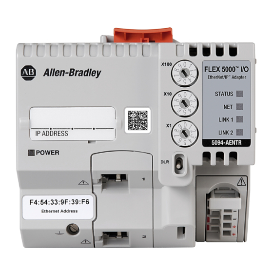
FLEX 5000 EtherNet/IP Adapters with RJ45 Ports
Catalog Numbers 5094-AENTR, 5094-AENTRXT, 5094-AEN2TR, 5094-AEN2TRXT
Topic
Product Overview
The FLEX 5000™ EtherNet/IP Adapters with RJ45 Ports perform the following functions:
• Facilitate high-speed data transfer across an EtherNet/IP network between FLEX 5000 I/O modules and a Logix 5000™ controller.
• Provide system-side power to FLEX 5000 I/O modules.
• The 5094-AENTR and 5094-AENTRXT adapters support as many as 8 FLEX 5000 I/O modules.
• The 5094-AEN2TR and 5094-AEN2TRXT adapters support as many as 16 FLEX 5000 I/O modules.
The adapters are configured with the Studio 5000 Logix Designer® application. For more information on how to use FLEX 5000 EtherNet/IP
Adapters with RJ45 Ports, including the compatible Logix 5000 controllers and Logix Designer application versions, see the publications that are
listed in
Additional Resources on page
15.
Page
5
5
6
7
8
9
11
12
13
13
14
15
Advertisement
Table of Contents

Related Manuals for Allen-Bradley FLEX 5000


Summary of Contents for Allen-Bradley FLEX 5000
-
Page 1: Table Of Contents
• The 5094-AEN2TR and 5094-AEN2TRXT adapters support as many as 16 FLEX 5000 I/O modules. The adapters are configured with the Studio 5000 Logix Designer® application. For more information on how to use FLEX 5000 EtherNet/IP Adapters with RJ45 Ports, including the compatible Logix 5000 controllers and Logix Designer application versions, see the publications that are... - Page 2 FLEX 5000 EtherNet/IP Adapters with RJ45 Ports ATTENTION: Read this document and the documents listed in the Additional Resources section about installation, configuration and operation of this equipment before you install, configure, operate or maintain this product. Users are required to familiarize themselves with installation and wiring instructions in addition to requirements of all applicable codes, laws, and standards.
- Page 3 FLEX 5000 EtherNet/IP Adapters with RJ45 Ports Environment and Enclosure ATTENTION: This equipment is intended for use in a Pollution Degree 2 industrial environment, in overvoltage Category II applications (as defined in EN/IEC 60664-1), at altitudes up to 2000 m (6562 ft) without derating.
- Page 4 FLEX 5000 EtherNet/IP Adapters with RJ45 Ports WARNING: Special Conditions for Safe Use: • This equipment shall be mounted in an ATEX/IECEx Zone 2 certified enclosure with a minimum ingress protection rating of at least IP54 (in accordance with EN/IEC 60079-15) and used in an environment of not more than Pollution Degree 2 (as defined in EN/IEC 60664-1) when applied in Zone 2 environments. The enclosure must be accessible only by the use of a tool.
-
Page 5: About The Adapter
Compatible zinc-plated, yellow-chromate steel DIN rail. DIN rail You can use a steel DIN rail such as the Allen-Bradley 199-DR1; 46277-3; EN50022 – 35 x 7.5 mm (1.38 x 0.30 in.). EtherNet/IP network You must install the network and all required components. -
Page 6: Adapter Dimensions
• The 5094-AEN2TR and 5094-AEN2TRXT adapters support as many as 16 FLEX 5000 I/O modules. • Before powerup, verify that the end cap is installed on the right-most installed FLEX 5000 terminal base. ATTENTION: Do not discard the end cap. Use this end cap to cover the exposed interconnections on the adapter module or the last terminal base on the DIN rail. -
Page 7: Set The Network Internet Protocol (Ip) Address
1770-4.1 for more information. You can use a zinc-plated yellow-chromate steel DIN rail such as the Allen-Bradley 199-DR1; 46277-3; EN50022 – 35 x 7.5 mm (1.38 x 0.30 in.). Power Considerations ATTENTION: Power to this equipment and all connected I/O must be supplied from a source compliant with the following: Isolated from Mains power via an approved Isolating Transformer constructed with Basic Insulation The FLEX 5000 EtherNet/IP adapter is powered by a Power RTB that is connected to an external power supply and installed on the adapter. -
Page 8: Install The Adapter Onto The Din Rail
IP address: • DHCP server • BootP DHCP EtherNet/IP Commissioning Tool - FLEX 5000 EtherNet/IP Adapters with RJ45 Ports only use the DHCP mode • RSLinx Classic software To reset the adapter to its initial out-of-the-box settings, set the rotary switches to 888 and cycle power. -
Page 9: Connect Power To The Adapter
FLEX 5000 EtherNet/IP Adapters with RJ45 Ports Connect Power to the Adapter Before you connect power to a FLEX 5000 EtherNet/IP adapter, complete the following tasks: • Read Power Considerations on page • Confirm that the external power supply that supplies module power is adequately sized all installed modules. For more information, see Power Considerations on page •... - Page 10 FLEX 5000 EtherNet/IP Adapters with RJ45 Ports 2. Strip insulation from the wires that you connect to the Power RTB. RTB Type Action Screw 0.33…2.1 mm (22…14 AWG) = Strip 12 ± 1 mm (0.47 ± 0.04 in.) of insulation from the wires.
-
Page 11: Connect The Adapter To An Ethernet/Ip Network
FLEX 5000 EtherNet/IP Adapters with RJ45 Ports RTB Type Action 1. Turn the screwdriver counter-clockwise to open the terminal. Screw 2. Remove the wire. 1. Insert and hold a screwdriver in the right-side terminal. Spring 2. Remove the wire. 3. Pull out the screwdriver. -
Page 12: Install The End Cap
If the end cap is installed on the adapter, you must remove it before you can install the I/O modules. For more information on how to install FLEX 5000 I/O modules, see the installation instructions available with each FLEX 5000 I/O module catalog number. -
Page 13: Power The Adapter
1. Turn off power to the Power RTB. IMPORTANT When you remove power from a FLEX 5000 EtherNet/IP adapter, you shut down power to all installed FLEX 5000 I/O modules. That is, all system-side power is removed. 2. If there are I/O modules installed, remove the I/O module from the terminal base next to the adapter. For more information on how to remove FLEX 5000 I/O modules, see the installation instructions available with each FLEX 5000 I/O module catalog number. -
Page 14: Specifications
FLEX 5000 EtherNet/IP Adapters with RJ45 Ports Specifications This table includes a subset of specifications for the adapter. For a complete list of specifications, see the FLEX 5000 Modules Specifications Technical Data, publication 5094-TD001. Attribute 5094-AENTR 5094-AENTRXT 5094-AEN2TR 5094-AEN2TRXT Temperature, operating IEC 60068-2-1 (Test Ad, Operating Cold) -40 °C <... -
Page 15: Additional Resources
5000 Control Systems. FLEX 5000 Digital I/O Modules User Manual, publication 5094-UM001 Provides information on how to install, configure, and operate FLEX 5000 digital I/O modules. FLEX 5000 Analog I/O Modules User Manual, publication 5094-UM002 Provides information on how to install, configure, and operate FLEX 5000 analog I/O modules. - Page 16 Rockwell Automation maintains current product environmental information on its website at http://www.rockwellautomation.com/rockwellautomation/about-us/sustainability-ethics/product-environmental-compliance.page. Allen-Bradley, FLEX 5000, Logix 5000, Rockwell Automation, Rockwell Software, and Studio 5000 Logix Designer are trademarks of Rockwell Automation, Inc. EtherNet/IP is a trademark of ODVA, Inc. Trademarks not belonging to Rockwell Automation are property of their respective companies.
Need help?
Do you have a question about the FLEX 5000 and is the answer not in the manual?
Questions and answers