Table of Contents
Advertisement
Quick Links
Advertisement
Table of Contents

Summary of Contents for HBM MGCplus
- Page 1 Operating Manual English MGCplus...
- Page 2 Fax +49 6151 803-9100 info@hbm.com www.hbm.com Mat.: 7-2002.0612 DVS: A0534-30 .0 HBM: public 03.2018 E Hottinger Baldwin Messtechnik GmbH. Subject to modifications. All product descriptions are for general information only. They are not to be understood as a guarantee of quality or...
-
Page 3: Table Of Contents
................Connecting the MGCplus in a tabletop housing/rack frame . - Page 4 Connection via the distributor board VT810/815i ....... . MGCplus A0534-30 .0 HBM: public...
- Page 5 ........MGCplus A0534-30 .0 HBM: public...
- Page 6 7.3.9.1 Direct entry of transducer characteristics ......MGCplus A0534-30 .0 HBM: public...
- Page 7 ........... MGCplus A0534-30 .0 HBM: public...
- Page 8 10.3.2 Format of the MGCplus measurement files ........
- Page 9 ................MGCplus A0534-30 .0 HBM: public...
- Page 10 Table of contents MGCplus A0534-30 .0 HBM: public...
-
Page 11: Safety Instructions
On-site regulations must be complied with at all times. There must be reference to the residual dangers connected with measurement technology. MGCplus A0534-30.0 HBM: public... - Page 12 In particular, any repair or soldering work on motherboards (replacement of components, apart from EPROMs) is prohibited. When exchanging com plete modules, use only original parts from HBM. The amplifier system and/or individual components are delivered from the factory with a fixed hardware and software configuration. Changes can only be made within the possibilities documented in the operating manuals.
- Page 13 Do not operate the device if the mains lead is damaged. If an amplifier channel is removed, the module must be sealed with a blind panel. Only operate built-in devices once they are installed in the housing pro vided. MGCplus A0534-30.0 HBM: public...
-
Page 14: Electromagnetic Compatibility
The insulation resistance of the connecting cables (v50V) must be at least 350V(AC). Electromagnetic compatibility The MGCplus device has been tested based on EMC product standard EN 61326-1:2013. This standard includes definitions of limit values and test levels for various electromagnetic environments. -
Page 15: Markings Used
By way of the CE mark the manufacturer guarantees that the product com plies with the requirements of the relevant EC directives (the Declaration of Conformity can be found at http://www.hbm.com/HBMdoc). Statutory waste disposal mark In accordance with national and local environmental protection and material recovery and recycling regulations, old devices that can no longer be used must be disposed of separately and not with normal household garbage. - Page 16 Bold text indicates menu items, as well as dialog and window headings in the program environment. Arrows between menu items indicate the se quence in which the menus and sub-menus are called up Sampling rate Bold text in italics indicates inputs and input fields in the user interfaces. MGCplus A0534-30.0 HBM: public...
-
Page 17: Introduction
These indicate which degree of protection a housing offers against contact or foreign objects (first digit) and moisture (second digit). MGCplus devices are available with degree of protection IP20. Code Degree of protection... -
Page 18: Notes On Documentation
S MGCplus Assistant, Documentation of the program for parameterization and control of the MGCplus measuring amplifier system. This manual contains all the information required to operate the MGCplus. Guides Several guides are available to help you: S The header shows you which section or sub-section you are currently reading. -
Page 19: System Description
3-byte measured value + 1-byte status). All measurement signals can be acquired in parallel, since each channel has its own ADU. No Sample & Hold or Multiplexer is used in the MGCplus. This ensures continu ous digital filtering and maximum signal stability. - Page 20 System description Digital signal conditioning Digital Filtering Display signal conditioning Communication Scaling, zero processor CPxx balance, ... Filtering, scaling, control zero balance, ... panel Single 8-channel channel module Serial bus module Fig. 3.1 Block diagram of MGCplus MGCplus A0534-30.0 HBM: public...
-
Page 21: Layout Of The Mgcplus Device
Introduction Layout of the MGCplus device Layout of the MGCplus device Connection boards (AP01i, AP815i, ...) Power CPxx supply Communication processor AB22A display and control unit Amplifier plug−in board (ML30B, ML55B, ML801B...) Fig. 3.2 Device layout with display and control unit AB22A Double-width connection boards (AP03i, AP455i) must be plugged into the odd-numbered slots. -
Page 22: Mgcplus Housing Designs
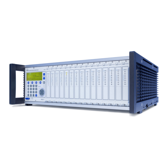
Introduction MGCplus housing designs MGCplus housing designs The MGCplus system is available with different housing versions (dimensions in mm; 1 mm = 0.03937 inches): Desktop housing TG 009E (173x171x367) Desktop housing TG 001E (255x171x367) Desktop housing TG 003E (458x171x367) 19” rack frame ER 003E (482x133x375) -
Page 23: Possible Amplifier/Connection Board Combination
Introduction MGCplus housing designs Possible amplifier/connection board combination Single-channel amplifier ML01B ML10B ML30B ML38B ML55B ML60B TEDS AP01i TEDS AP03i AP14 AP17 Torque / rotational speed Piezoresistive SG full bridge circuit T3...T10 transducer SG half bridge circuit Torque Voltage T1, T4, T5, TB1... - Page 24 Introduction MGCplus housing designs Multi-channel amplifiers ML801B ML455 ML460 AP402i AP418i AP455i AP455iS6 AP460i AP801 Current−fed piezo− SG full bridge circuit AP801S6 electric transducer SG half bridge circuit AP809 Thermo−resistors Thermo−resistors PT100 AP810i SG quarter bridge circuit Ohmic resistor Inductive half bridge...
- Page 25 Introduction MGCplus housing designs Special function modules ML70B ML71B ML74B ML77B ML78B Digital output AP71 Digital input AP72 Serial I/O Analog output AP74 CANHEAD ProfiBus AP75 CANBus RS232, RS422, Serial I/O RS485 I/O AP77 CANHEAD HBM hardware AP78 MGCplus A0534-30.0 HBM: public...
-
Page 26: Installation Of The Cp52 Communication Processor
► Fit the power supply cover of the NT030 and screw the cover in place. The process is similar when subsequently installing a CP52 communication processor in an MGCplus housing (type "D" or type "E") that was initially configured without a communication processor. - Page 27 CP switch (S3). It must be set to "yes" so the system can be started with the communication processor. Then the housing cover can be closed again. MGCplus A0534-30.0 HBM: public...
- Page 28 General plan of the interface switches Due to the new functions of the CP52 communication processor, a firmware update of the AB22A display and control unit is necessary. The firmware update program MGCpLoad and the latest firmware are available from www.hbm.com/downloads. MGCplus A0534-30.0 HBM: public...
-
Page 29: Conditions At The Place Of Installation
S The devices are classified in overvoltage category II, degree of pollution 2. S Install the device so that it can be disconnected from the mains at any time without difficulty. S It is safe to operate the MGCplus up to an altitude of 2000 m. MGCplus A0534-30.0 HBM: public... -
Page 30: Maintenance And Cleaning
Introduction Maintenance and cleaning Maintenance and cleaning The MGCplus system devices are maintenance-free. Please note the follow ing points when cleaning the housing: CAUTION Disconnect the mains plug from the socket before cleaning. S Clean the housing with a soft, slightly damp (not wet!) cloth. You should never use solvents, since this may damage the labeling on the front panel and the display field. -
Page 31: Connection
Voltage adaptation to a 115V/230V network occurs automatically. The power pack fan is temperature-controlled and is automatically switched on only when necessary. If the MGCplus is connected with the mains cable included with delivery, a Grounding safe and reliable connection via the protective conductor is ensured. -
Page 32: Synchronization Of Multiple Cp52 Devices
Connection Connecting the MGCplus in a tabletop housing/rack frame 4.1.2 Synchronization of multiple CP52 devices 4.1.2.1 Synchronization of multiple CP52 devices via a synchronization jack Connected devices are automatically detected and synchronized when syn chronization jacks are occupied. Connect the master device with the first slave device (Sync In, X1) via the output jack (Sync Out, X2). - Page 33 >15 m. We recom mend that you attach a termination resistor connector to the Sync Out socket (X2) of the last sync slave. This connector is available from HBM on request. The maximum number of MGCplus units that can be synchronized is 32.
-
Page 34: Synchronization Of Cp52 With Cp22/Cp42
Connect the system that will work as the sync master last of all. 4.1.3 Synchronization of CP52 with CP22/CP42 The synchronization jack enables MGCplus systems with CP52 to be synchronized with MGCplus systems with CP22/CP42. To do this note the following points: Both CP42 and CP52 can be the synchronization master. - Page 35 Connecting the MGCplus in a tabletop housing/rack frame CP42 RS 232 CARDBUS USB DEVICE USB HOST YE SLAVE RD ERROR ETHERNET GN MASTER SYNC CTRL I/O 24V 2 GN Fig. 4.2 Example of synchronizing two MGCplus systems equipped with CP52 and CP42. MGCplus A0534-30.0 HBM: public...
-
Page 36: Shielding Design
(EMI) and the permissible electromagnetic interference emis sions (EME), has become increasingly important over the years. The HBM Greenline shielding design The measurement chain is completely enclosed by a Faraday cage by appropriate routing of the cable shield. The cable shield is extensively con... - Page 37 In order to minimize the effect of electromagnetic interference and differ ences in potential, the signal ground and ground (or shielding) are designed to be physically separate in the HBM devices. The ground connection or a separate mains protective conductor should serve as the ground connec...
- Page 38 Sense lead (-) RB / 2 (on the transducer) Hsg. = Housing HBM recommends this connection technique for measuring amplifiers ML10B, ML30B, ML38B, ML55B and ML455 with connection boards AP01i, AP03i, AP14 and AP455i with very small measuring ranges, in environments especially subject to interference and when long cables are used.
-
Page 39: Connecting The Transducer
For cable lengths >50m, a resistor of half the value of the bridge resistance (RB/2) must be activated on the transducer instead of each feedback bridge. If the transducers are calibrated in a 6-wire configuration, resistors must be activated directly into the sense lead. MGCplus A0534-30.0 HBM: public... - Page 40 Connection Connecting separate TEDS modules AP402i View of the mating connector (solder side) Hsg. TEDS TEDS data MGCplus A0534-30.0 HBM: public...
- Page 41 Connection Connecting separate TEDS modules AP460i Hsg. Cable color code: wh= white; bk= black; bu= blue; TEDS rd= red; ye= yellow; TEDS data gn= green; gy= gray MGCplus A0534-30.0 HBM: public...
-
Page 42: Sg Full Bridges, Inductive Full Bridges
(-) Bridge excitation voltage (+) Measurement signal (-) Hsg. Hsg. Hsg. Cable shield Sense lead (+) Sense lead (-) Cable color code: wh= white; bk= black; bu= blue; rd= red; ye= yellow; gn= green; gy= gray MGCplus A0534-30.0 HBM: public... -
Page 43: Full Bridge Circuits On Ap810I/Ap815I
(+) Measurement signal (-) Hsg. Hsg. Hsg. Hsg. Cable shield Sense lead (+) Subchannel 5...8 Sense lead (-) Cable color code: wh= white; bk= black; bu= blue; rd= red; ye= yellow; gn= green; gy= gray MGCplus A0534-30.0 HBM: public... -
Page 44: Strain Gage Half Bridges, Inductive Half Bridge Circuits
Bridge excitation voltage (-) Bridge excitation voltage (+) Hsg. Hsg. Hsg. Cable shield Sense lead (+) Sense lead (-) Cable color code: wh= white; bk= black; bu= blue; rd= red; ye= yellow; gn= green; gy= gray MGCplus A0534-30.0 HBM: public... -
Page 45: Lvdt Transducers
Connection LVDT transducers 4.3.5 LVDT transducers AP455iS6 AP455i LVDT transducers Measurement signal (+) Bridge excitation voltage (-) Bridge excitation voltage (+) Measurement signal (-) Cable shield Hsg. Hsg. Sense lead (+) Sense lead (-) MGCplus A0534-30.0 HBM: public... -
Page 46: Strain Gage Half Bridges On Ap810I
Strain gage half bridges on AP810i AP810i Subchannel Subchannel Subchannel Subchannel Subchannel 1...4 Sense lead (-) Bridge excitation voltage (-) wh/rd wh/gn Measurement signal (+) Cable shield Hsg. Hsg. Hsg. Hsg. Subchannel 5...8 Bridge excitation voltage (+) wh/br Sense lead (+) MGCplus A0534-30.0 HBM: public... -
Page 47: Strain Gage Half Bridges On Ap815I
SGs are separated by a line. With decentralized half bridge circuits the measured value must be acquired at both ends of the connecting line between the active SGs. With standard half bridge circuits a connector can also be bridged. MGCplus A0534-30.0 HBM: public... -
Page 48: Single Strain Gage
Connection Single strain gage 4.3.8 Single strain gage 4.3.8.1 Single strain gage on AP14 AP14 Sense lead (-) Excitation voltage (-) Hsg. Excitation voltage (+) Measurement signal (+), sense lead (+) Three-wire connection Four-wire connection MGCplus A0534-30.0 HBM: public... -
Page 49: Single Strain Gage On Ap814Bi
Hsg. Hsg. Hsg. Hsg. Hsg. Hsg. Hsg. Hsg. Hsg. Cable shield Excitation voltage (-) Sense lead (-) Three-wire connection Cable color code: wh= white; bk= black; bu= blue; rd= red; ye= yellow; gn= green; gy= gray MGCplus A0534-30.0 HBM: public... -
Page 50: Single Strain Gage On Ap815I
Sense lead (-) Hsg. Hsg. Hsg. Cable shield Hsg. Subchannel Measurement signal (+), 5...8 wh/gn sense lead (+) Excitation voltage (+) Cable color code: wh= white; bk= black; bu= blue; rd= red; ye= yellow; gn= green; gy= gray MGCplus A0534-30.0 HBM: public... -
Page 51: Sg Chains And Strain Gage Rosettes On Ap815I
You can operate a maximum of eight SGs at 120 ohms with a 5-V current feed. Make certain that sensor point 2' of the SG chain is as close as possi ble for the individual strain gages and the distances between the individual strain gages are short. MGCplus A0534-30.0 HBM: public... - Page 52 Hsg. Cable shield Subchannel 1...4 Measurement signal (+), sense lead (+) Excitation voltage (+) Subchannel Subchannel 5...8 Excitation voltage (-) Subchannel Sense lead (-) Hsg. Cable shield Measurement signal (+), sense lead (+) Excitation voltage (+) MGCplus A0534-30.0 HBM: public...
-
Page 53: Torque Measurement
Torque measurement signal, frequency output (-) Hsg. 7/5 6 Cable shield Calibration signal trigger (approx. 5V) Ground Cable color code: wh= white; bk= black; bu= blue; rd= red; ye= yellow; gn= green; gy= gray Does not apply to version KF1. MGCplus A0534-30.0 HBM: public... - Page 54 Torque measurement signal, frequency output (+) Torque measurement signal, frequency output (-) Hsg. Cable shield Ground Cable color code: wh= white; bk= black; bu= blue; rd= red; ye= yellow; gn= green; gy= gray Information The torque flanges must be powered externally. MGCplus A0534-30.0 HBM: public...
-
Page 55: Rotational Speed Measurement (Symmetrical Signals)
Rotational speed measurement signal, 0 (-) Rotational speed measurement signal, 90 (-) Hsg. Cable shield Rotational speed measurement signal, 90 (+) Cable color code: wh= white; bk= black; bu= blue; rd= red; ye= yellow; gn= green; gy= gray MGCplus A0534-30.0 HBM: public... - Page 56 Rotational speed measurement signal, 0 (-) Rotational speed measurement signal, 90 (-) Hsg. Cable shield Rotational speed measurement signal, 90 (+) Cable color code: wh= white; bk= black; bu= blue; rd= red; ye= yellow; gn= green; gy= gray MGCplus A0534-30.0 HBM: public...
-
Page 57: Rotational Speed Measurement (Symmetrical Signals) With Reference Pulse
Rotational speed measurement signal, 90 (-) Hsg. Cable shield Reference signal (+) Reference signal (-) Rotational speed measurement signal, 90 (+) 5V (out) Cable color code: wh= white; bk= black; bu= blue; rd= red; ye= yellow; gn= green; gy= gray MGCplus A0534-30.0 HBM: public... - Page 58 Rotational speed measurement signal, 90 (-) Hsg. Cable shield Reference signal (+) Reference signal (-) Rotational speed measurement signal, 90 (+) Cable color code: wh= white; bk= black; bu= blue; rd= red; ye= yellow; gn= green; gy= gray MGCplus A0534-30.0 HBM: public...
-
Page 59: Torque Shaft (T4A, T5, Tb1A)
* SG full bridge only Transducer in a 6-wire configuration: see connection diagram page 42 Cable color code: wh= white; bk= black; bu= blue; rd= red; ye= yellow; gn= green; gy= gray MGCplus A0534-30.0 HBM: public... - Page 60 Torque shaft (T4A, T5, TB1A) Supply voltage +16V No function (for special versions only) No function (for special versions only) Supply voltage +8V Supply voltage +5V Jumper (factory settings 0V) Connection board AP 460 (side view) MGCplus A0534-30.0 HBM: public...
-
Page 61: Rotational Speed Measurement With Inductive Transducers
4.3.11.2 Rotational speed measurement with inductive transducers AP460i Rotational speed measurement signal 1 kW 5 kW = 30V Rotational speed measurement signal Inductive tachometer (T-R coil) Please note the setting information for T-R coils on page 152. MGCplus A0534-30.0 HBM: public... -
Page 62: Thermocouples
Miniature thermo connector, uncompensated Compensating line Thermocouple − Compensating line Miniature thermo connector (see table for matching type) Type Thermal material 1 (+) Thermal material 2 (-) Iron Copper-nickel Nickel‐chrome (color code Nickel‐aluminum (color code green) white) Copper Copper-nickel MGCplus A0534-30.0 HBM: public... -
Page 63: Dc Voltage Sources
DC voltage sources 4.3.13 DC voltage sources AP01i AP03i Maximum input voltage against ground = 12V Supply voltage zero Cable shield Hsg. Hsg. With a potential-free DC voltage source you must connect pin 15 with pin 6. MGCplus A0534-30.0 HBM: public... - Page 64 Connection DC voltage sources AP402i Maximum input voltage against ground = " 100V Cable shield Hsg. MGCplus A0534-30.0 HBM: public...
- Page 65 Connection DC voltage sources AP801 AP801S6 Maximum input voltage against ground = +50V Hsg. Supply voltage 8V/16V Power supply 0V Hsg. *) For information on switching the supply voltage see next page MGCplus A0534-30.0 HBM: public...
- Page 66 Connection DC voltage sources Supply voltage +16V No function (for special versions only) Jumper No function (for special versions only) Supply voltage +8V Connection board AP 801S6 (side view) MGCplus A0534-30.0 HBM: public...
- Page 67 Supply voltage 5V/8V/16V Power supply 0V Hsg. For information on switching the supply voltage see next illustration Supply voltage +5V Supply voltage +8V Supply voltage +16V No function (factory setting) Jumper Connection board AP402i (side view) MGCplus A0534-30.0 HBM: public...
- Page 68 Separate signal and supply voltage zero, power lines not corrected Since the bridge excitation voltage used to supply the active transducer is symmetrical to GND/ground, the design of the active transducer must without exception be potential-free! MGCplus A0534-30.0 HBM: public...
- Page 69 Separate signal and supply voltage zero, power lines fully corrected. Since the bridge excitation voltage used to supply the active transducer is symmetrical to GND/ground, the design of the active transducer must without exception be potential-free! MGCplus A0534-30.0 HBM: public...
-
Page 70: Dc Power Sources
Connection DC power sources 4.3.14 DC power sources AP01i AP03i Maximum input voltage against ground = 12V Supply voltage zero Hsg. Hsg. Cable shield MGCplus A0534-30.0 HBM: public... - Page 71 Connection DC power sources AP402i Maximum input voltage against ground = ±100V Hsg. Cable shield MGCplus A0534-30.0 HBM: public...
-
Page 72: Resistors, Pt100
Connection Resistors, Pt100 4.3.15 Resistors, Pt100 AP835 Excitation voltage (-) Measurement signal (-) Hsg. Cable shield Measurement signal (+) Excitation voltage (+) MGCplus A0534-30.0 HBM: public... -
Page 73: Frequency Measurement Without Directional Signal
Frequency measurement without directional signal AP01i AP03i Supply voltage zero Frequency generator/ pulse Hsg. Hsg. Cable shield generator Rotational speed/pulse signal 1 (frequency f Deactivate the analysis of the f signal in this mode (factory setting: Off), see page 159. MGCplus A0534-30.0 HBM: public... -
Page 74: Frequency Measurement With Directional Signal
Hsg. Hsg. Cable shield Frequency generator / Rotational speed/pulse pulse signal 1 (frequency f generator Pulse signal 2 (frequency f Activate the analysis of the f_2 signal in this mode (factory setting: Off), see page 159 MGCplus A0534-30.0 HBM: public... -
Page 75: Pulse Counting, Single-Pole
Connection Pulse counting, single-pole 4.3.18 Pulse counting, single-pole AP01i AP03i AP460i AP17 Industrial pulse generators Zero index Transducer error MGCplus A0534-30.0 HBM: public... -
Page 76: Pulse Counting, Differential
Connection Pulse counting, differential 4.3.19 Pulse counting, differential AP17 AP460i Zero index signal + Zero index signal - Industrial pulse generators Transducer error MGCplus A0534-30.0 HBM: public... -
Page 77: Active Piezoelectric Transducers
(for example where it enters the switch cabinet). HBM recommends Triaxial cable for this purpose. MGCplus... -
Page 78: Piezoresistive Transducers
Connection Piezoresistive transducers 4.3.21 Piezoresistive transducers AP01i AP03i Measurement signal (+) Bridge excitation voltage (-) Bridge excitation voltage (+) Measurement signal (-) Hsg. Hsg. Cable shield Sense lead (+) Sense lead (-) MGCplus A0534-30.0 HBM: public... -
Page 79: Potentiometric Transducers
Cable shield Sense lead (+) Sense lead (-) AP836 Subchannels Subchannel 1...4 Measurement signal (+) Bridge excitation voltage (-) Bridge excitation voltage (+) Cable shield Hsg. Hsg. Hsg. Hsg. Sense lead (+) Subchannel 5...8 Sense lead (-) MGCplus A0534-30.0 HBM: public... -
Page 80: Connection Via The Distributor Board Vt810/815I
Measurement signal (+) Hsg. Cable shield Measurement signal (-) Measurement signal (-) Bridge excitation voltage (+) wh/br wh/br Bridge excitation voltage (+) Sense lead (+) Sense lead (+) Hsg. Cable shield The color code refers to 1-KAB156-3. MGCplus A0534-30.0 HBM: public... - Page 81 Connecting diagram Measuring point Distributor board VT810/815i Connection board AP810i/815i D‐Sub25 SG 1 RJ45 1-Kab156-3 D‐Sub25 1-Kab263-3 SG 2 1-Kab156-3 D‐Sub25 1-Kab263-3 1-AP810i 1-AP815i SG 8 1-Kab156-3 Extensive connection instructions are enclosed with the distributor board. MGCplus A0534-30.0 HBM: public...
-
Page 82: Connecting Canhead Modules
NT030 power pack, you can connect a maximum of 12 modu les per board and a maximum of 25 modules per MGCplus device (a maxi mum of 256 channels per CP42 and 512 channels per CP52 in total). The combination of NT040 with CP52 enables up to 50 modules per MGCplus device to be connected. -
Page 83: Communication Card Ml74B
Bus error CONFIG Yellow The assigned CANHEADS are being set up AP74 Yellow Power supply via AP74 STATUS No power supply via AP74 Error in power supply via AP74 SCAN Yellow Bus scan is being performed MGCplus A0534-30.0 HBM: public... -
Page 84: Ap74 Connection Board
Connection AP74 connection board 4.4.2 AP74 connection board AP74 LED color Meaning Green Normal status in operation Short circuit or force overshoot None Power supply turned off MGCplus A0534-30.0 HBM: public... -
Page 85: Inputs And Outputs, Remote Controls
You can assign the following functions to the digital inputs: S Start to record measured data with an external trigger The status of the inputs and outputs can also be queried with the MGCplus terminal commands. Outputs (0 V ... 24 V) - Page 86 Connection Inputs and outputs, remote controls 24V DC Fig. 4.5 Wiring example for the "Start Trigger" function at the CP52 control inputs MGCplus A0534-30.0 HBM: public...
-
Page 87: Analog Output On The Front Panel
4.5.3 Connection boards AP01i/AP03i/AP14/AP17 In addition to the transducer connection, the connection boards also provide several output and control signals, depending on the option selected. They are explained in greater detail in the following sections. MGCplus A0534-30.0 HBM: public... -
Page 88: Socket Assignment Ap01I/Ap03I/Ap14/Ap17
Pin 12 Analog to Pin 13 Tab. 4.1 Sct2 Assignment of outputs Analog outputs S On pin 12 the analog output signal V is present. The connected load resistor must be greater than 5 kohms. MGCplus A0534-30.0 HBM: public... - Page 89 AB22A display and control unit, i.e. in REMOTE operating mode. The assignment of these remote controls is freely selectable. The possible functions are described in section 8 Additional functions . Information In the factory settings the contacts are not assigned. MGCplus A0534-30.0 HBM: public...
- Page 90 MLxx Additional instructions for AP17: Pin assignment of the input socket Function Shield Zero index (+) Input Zero index (-) Input Ground Transducer supply voltage -16V (max. 500mA) Output Transducer supply voltage +16V (max. 500mA) Output MGCplus A0534-30.0 HBM: public...
- Page 91 Termination resistors must be connected for long lines (>100m) and high frequencies (>200kHz). To do this the 3x DIP switch S2 on the motherboard of the AP17 must be switched to "ON". AP17 Switch S2 Fig. 4.6 AP17 component layout MGCplus A0534-30.0 HBM: public...
-
Page 92: Ap460I Connector Pin Assignment
Connection Symmetrical input signals (RS 422): Input a/input b Asymmetrical input signal, bipolar: Input a (signal ground on input b) Asymmetrical input signal, unipolar: Input a (signal ground on pin 10, input b must remain open) MGCplus A0534-30.0 HBM: public... -
Page 93: Ap77
Inputs and outputs, remote controls Profibus 4.5.3.3 AP77 The pin assignment of the 9‐pin Sub‐D socket complies with Profibus stan dards IEC 61158/61784. Function RS485-B RS485-RTS RS485-A Information Further information can be found in the ML77B operating manual. MGCplus A0534-30.0 HBM: public... -
Page 94: Inputs And Outputs Of Ap75
The digital outputs must be operated with an external current feed (12 V...24 V). The AP75 connection board can be operated together with the special function modules ML78B or ML70B. Wiring example for using an analog output. MGCplus A0534-30.0 HBM: public... - Page 95 Inputs and outputs, remote controls Please note that the measuring systems of the digital inputs and outputs are separated from each other. Wiring example for use of a digital input. (digital inputs 4 and 7 in this case) MGCplus A0534-30.0 HBM: public...
- Page 96 Connection Inputs and outputs, remote controls Analog outputs V and V have a common ground system that is sepa rated from the ground systems of the digital inputs and outputs. Wiring example for using analog output MGCplus A0534-30.0 HBM: public...
-
Page 97: Analog Outputs On The Ap78
VO2 can be digitally filtered (together with ML78B). The AP78 connection GND A03 board can be used together with the ML78B and the freely programmable GND A04 ML70B module (CoDeSys). GND A05 A010 GND A010 GND V01 GND V02 MGCplus A0534-30.0 HBM: public... - Page 98 Connection Inputs and outputs, remote controls MGCplus A0534-30.0 HBM: public...
-
Page 99: Starting Up
After the initial start-up is performed and the amplifier module is adapted to your transducer, you will be ready to become familiar with the remaining functions and possibilities of the MGCplus measuring amplifier system. S Unpack the MGCplus. S Check the MGCplus for damage. - Page 100 S Turn the device on using the POWER button on the front of the device. The AB22A is initialized (all the LEDs light up briefly) and detects the components present. MGCplus initialization Baud rate detection ... If a transducer is not connected, an overload is displayed! After the opening display, the measured value of image type "1 measured...
- Page 101 Devices in the desktop housing and rack frame We recommend first setting the Language if you want to use a language other than German. System Display Amplifier Options Password Save/load Recording Interface Print Language Time LANGUAGE Language: Deutsch Deutsch English Francais MGCplus A0534-30.0 HBM: public...
- Page 102 Starting up Devices in the desktop housing and rack frame MGCplus A0534-30.0 HBM: public...
-
Page 103: Functions And Symbols Of The Ab22A
Help texts. Setup mode: Menu navigation Alphanumeric keypad Enter key For entering numbers, letters Activates the settings that have and special characters in the been made Power switch edit fields MGCplus A0534-30.0 HBM: public... -
Page 104: Display
(factory settings). Pressing the Switch key takes you to Setup mode, where you can configure the sys tem, display, amplifier and additional functions. We recommend first setting the Language if you want to use a language other than German. MGCplus A0534-30.0 HBM: public... -
Page 105: Display In Measuring Mode
Peak values Limit values Gross Channel Number of the selected channel (maximum 16 or 16.8 with multi- channel Measure modules) Status line Measure Function key assignment (shown here in measuring mode, first level) Unit Measured value MGCplus A0534-30.0 HBM: public... - Page 106 LV Off Measure Display with image type "Recording" SAMPLING RATE: 50Hz TIME: 00: 00: 00 PERIODS: 100 To the next image type with -4.0S 16.0S FILE NAME: MGCP0000.MEA 120 MB FREE Load AP1 Acal Test series 1 MGCplus A0534-30.0 HBM: public...
- Page 107 Status of limit switches. If the set activation level of a limit switch is ex ceeded, the switch number has a black background in the display. Example: Activation level of limit switch 1 is exceeded Local Remote control turned off Remote Remote control turned on MGCplus A0534-30.0 HBM: public...
- Page 108 Functions and symbols of the AB22A Display Channel Channel number of a single-channel module Channel Channel number of a multi-channel module First number is the slot number Second number is the number of the subchannel MGCplus A0534-30.0 HBM: public...
-
Page 109: Messages Of Ab22A/Ab32
Error during configuration a) Amplifier types x, y, z do not match Check the fitting of the MGCplus device. of channels x, y, z! the types of the configuration file (mod ules mixed up). b) There is no amplifier module present. -
Page 110: Ab22A In Setup Mode
Functions and symbols of the AB22A AB22A in Setup mode AB22A in Setup mode The settings of the MGCplus device are combined together in function- related groups. After you press the Switch key you are in the setting dialog and the selection bar appears in the display. - Page 111 Save/load Recording Display PASSWORD Interface delete User: Print Setting level 2 Language Password: chang Display Selection bar Add user Access: User: Display Setup window Password: Access: Operator Cancel Setup window Fig. 6.1 Example: System setting password MGCplus A0534-30.0 HBM: public...
-
Page 112: Call Menus
The current setup window may lead to additional setting levels. Selection level 1 System Display Amplifier Press-fitting Selection bar Selection level 2 Password Pull‐up menu Save/load Recording Interface Print Light bar Language Time Deutsch Setting level 1 English Deutsch Francais Selection window MGCplus A0534-30.0 HBM: public... -
Page 113: Exit Menus
The confirmation prompt shown on the side ap Cancel pears for this purpose. In the factory settings Yes is selected. Confirm with MGCplus A0534-30.0 HBM: public... -
Page 114: Channel Selection In Measuring Mode
► The channel input field appears in the display with the desired slot num ber. (If you confirm now with , the first subchannel, in this case 3.1, is selected). ► Enter a dot and the desired subchannel number after it. ► Confirm with MGCplus A0534-30.0 HBM: public... -
Page 115: Channel Selection In Setup Mode
. The data is permanently saved as soon as you exit Setup mode and confirm the confirmation prompt with Yes. Amplifier Volatile memory (8h) Factory settings Save Load Save permanently EPROM EEPROM Parameter set 1...8 MGCplus A0534-30.0 HBM: public... -
Page 116: Drop-Down Menus
Four different kinds of dialog boxes in setup windows S Switch on or off in activation fields Gross The selected field appears in reverse video. Confirm the selection with A tick appears in selected boxes ("activated"). Pressing the activation button again cancels activation. MGCplus A0534-30.0 HBM: public... - Page 117 2.5V the selection field opens up. Select with the cursor keys and confirm your setting with . In the documentation (not in the display) fields of this kind are identified by an arrow pointing down . MGCplus A0534-30.0 HBM: public...
- Page 118 3 upper-case letters and 3 lower-case letters. A number appears the first time you press the key, with letters appearing after it is pressed again. To enter consecutive letters that are both on the same key, press the cursor key between the letters . MGCplus A0534-30.0 HBM: public...
- Page 119 Buttons Cancel The selected field appears in reverse video. Confirm with . If the button label is followed by three dots, (change...), an additional setup window ap Change... pears after confirmation. MGCplus A0534-30.0 HBM: public...
-
Page 120: Mgcplus A0534-30 .0 Hbm: Public
Functions and symbols of the AB22A AB22A in Setup mode MGCplus A0534-30.0 HBM: public... -
Page 121: Measuring
General information This section describes the steps you will need to follow to perform a mea surement with MGCplus. At the beginning of each section an example ex plains the transducer-specific details for adapting the amplifier modules. Af ter you have adapted the amplifier modules you can start with the measurements. -
Page 122: General Principles For Adjusting A Measurement Channel
S Characteristic curve (zero point and nominal (rated) value) ► Adjust amplifier Once these steps are complete the most urgent settings and adaptations have been made and simple measurements are possible. The following steps are optional MGCplus A0534-30.0 HBM: public... - Page 123 S Gross/Net/Peak value Output characteristics Output characteristics Pt.1: Pt.1: 0.0000 0.0000 0.0000 0.0000 S Output characteristics 100.0000 100.0000 0.0000 0.0000 Pt.2: Pt.2: ► Adjusting additional functions (if necessary) S Limit values, peak values S Remote control contacts, … MGCplus A0534-30.0 HBM: public...
-
Page 124: Adapting To The Transducer
Button for opening the "Characteristic curve points" setup window where you can calibrate characteristic curve points 1 and 2. Adjust amplifier Button for adapting the amplifier to the entries for the zero point and nominal (rated) value. MGCplus A0534-30.0 HBM: public... -
Page 125: Extended Functions Of The Ml38B
The values of the coefficients can be found on the transducer calibration certificate. The amplifier itself requires coefficients (C0 ...C3) standardized to the value 1. The coefficients from the calibration certificate (A0 ...A3) are automati cally converted before they are forwarded to the amplifier (also in MGCplus‐Assistant). MGCplus A0534-30.0 HBM: public... -
Page 126: Teds Transducers
This means that the same cables can be used as for transducers that do not have TEDS. Some connection boards of the MGCplus system such as the AP01i also offer the possibility of entering TEDS data signals to two separate pins (ground and TEDS data signal). - Page 127 TEDS chip if it supports this functionality. For an overview of which connection board/amplifier combinations are TEDS-capable, see section 3.6. The amplifiers must be equipped with the current firmware, which is available from www.hbm.com/downloads. MGCplus A0534-30.0 HBM: public...
-
Page 128: Signal Conditioning
Taring affects the net display. Disable zero/disable taring You can disable the zero balance and/or taring. The disabling applies to all triggering mechanisms (F‐keys, control inputs, software). A brief example will clarify the difference between a zero balance and taring: MGCplus A0534-30.0 HBM: public... - Page 129 7 kg −>T<− 61 kg 7 kg 7 kg after 7 kg after 0 kg Component 2 15 kg (total content of 61 kg 15 kg 8 kg (component 2 only) 8 kg the container) MGCplus A0534-30.0 HBM: public...
- Page 130 .5Hz Bessel: Butterworth: .10Hz The nominal (rated) values of the filters provided by the AB22A display and control unit and by the MGCplus Assistant and catman software are oriented towards the -1 dB values (see technical data). Bessel MGCplus A0534-30.0 HBM: public...
-
Page 131: Display
Decimal places 1 (20.0kg) Step 1 means display jumps every 100g Step 5 means display jumps every 500g Decimal places 3 (20.000kg) Step 1 means display jumps every 1g Step 5 means display jumps every 5g MGCplus A0534-30.0 HBM: public... -
Page 132: Analog Outputs (Single-Channel Modules Only)
However, you can also change the output characteris Gross Net Output Vo1: Output Vo2: tics with direct entry. Output characteristics 0.0000 0.0000 Pt.1: 100.0000 0.0000 Pt.2: User unit (ppm, etc.) Gross Pt.2 Comb. PV Pt.1 Analog output: (V) MGCplus A0534-30.0 HBM: public... - Page 133 . Select kg as the unit and confirm with to switch to the Zero point edit field and enter the value 0 in 8. Use the left edit field. Confirm with 9. Unload the load cell. MGCplus A0534-30.0 HBM: public...
- Page 134 Type SG full bridge circuit Current feed 5V Unit: kg mV/V measure 0.0000 ... 0.0000 ... Zero pt.: Nom. val.: 50.0000 ... 2.0000 ... calibrate... calibrate... Adjust amplifier 0.0000 ... Gage factor: MGCplus A0534-30.0 HBM: public...
-
Page 135: Adapting To The Transducer
Adapting to the transducer Adapting to the transducer 7.3.1 SG transducers SG transducers (load cells and force transducer from HBM) are passive transducers that have the following features: S They must be supplied with an excitation voltage (carrier frequency or direct voltage) -
Page 136: Direct Entry Of Transducer Characteristics
. Select kg as the unit and confirm with to switch to the Zero point edit field and enter the value 0 in 9. Use the left edit field. Confirm with 10. Unload the load cell. MGCplus A0534-30.0 HBM: public... - Page 137 Entry 10.0 kg Step 1 means display jumps every 100g Step 5 means display jumps every 500g Entry 10.000 kg Step 1 means display jumps every 1g Step 5 means display jumps every 5g MGCplus A0534-30.0 HBM: public...
- Page 138 ANALOG OUTPUTS CHANNEL1 Output Vo1: Gross Output Vo2: Net 24. Use the Switch key to go to measuring mode and confirm the con Output characteristics 0.0000 0.0000 Pt.1: firmation prompt with 100.0000 0.0000 Pt.2: MGCplus A0534-30.0 HBM: public...
-
Page 139: Calibrating The Characteristic Curve Of The Transducer
Zero point edit field and enter the value 0 in 9. Use the left edit field. Confirm with 10. Use to switch to the Nominal (rated) value edit field and enter the value 10 in the left edit field. Confirm with MGCplus A0534-30.0 HBM: public... -
Page 140: Strain Gages
(SG). A detailed de scription of SG technology can be found in the book "An Introduction to the Technology of Measuring with Strain Gages" (author Karl Hoffmann, pub lished by HBM Darmstadt). MGCplus A0534-30.0 HBM: public... - Page 141 = strain gage sensitivity (gage factor) Fig. 7.1 Wheatstone bridge You can use the MGCplus measuring system to measure the strain of one SG or the total strain of multiple SGs. The table below summarizes the pos sible bridge circuits and the necessary device configuration:...
- Page 142 (measuring on a bending beam, etc.). The most important characteristic value of a SG is the gage factor. The MGCplus measurement system automatically switches to strain mea surements if a gage factor >0 is entered. The zero point and measuring range are scaled in mm/m.
-
Page 143: Direct Entry Of Transducer Characteristics
Since the amplifier automatically changes the basic unit from mV/V to m/m after the gage factor is entered, the physical quantity plays no role in this example. The menu window shown here is based on the display in the factory settings. MGCplus A0534-30.0 HBM: public... - Page 144 Step 5 means display jumps every 5 mm/m 17. Use the Switch key to go to measuring mode and confirm the con firmation prompt with 18. Perform a zero balance in unloaded state ( function key in the fac tory settings). MGCplus A0534-30.0 HBM: public...
-
Page 145: Inductive Transducers
Adapting to the transducer 7.3.3 Inductive transducers Inductive transducers (for example force transducer from HBM) are passive transducers that have the following features: S They must be supplied with an excitation voltage (carrier frequency) S They are inductive half or full bridge circuits... -
Page 146: Direct Entry Of Transducer Characteristics
Confirm with 10. Move the transducer to the zero position. measure 11. Use to switch to the button and confirm with (the measured value appears in the right edit field of Zero point) MGCplus A0534-30.0 HBM: public... - Page 147 Step 1 means display jumps every 0.001mm Step 5 means display jumps every 0.005mm 19. Go back to the pull-up menu with 20. Use the Switch key to go to measuring mode and confirm the con firmation prompt with MGCplus A0534-30.0 HBM: public...
-
Page 148: Calibrating The Characteristic Curve Of The Transducer
Unit selection field and press . Select mm Cancel as the unit and confirm with to switch to the Zero point edit field and enter the value 0 in 9. Use the left edit field. Confirm with MGCplus A0534-30.0 HBM: public... - Page 149 Point 1: 0.0000 0.0021 measure Point 2. Now if you press , a measurement starts and the current Point 2 10.000 5.0018 measure Cancel measured value appears in mV/V on the left next to the button measure MGCplus A0534-30.0 HBM: public...
- Page 150 (left 15 for the display, right 10 for the analog output). 0.0000 0.0000 Pt.1: 100.0000 0.0000 Pt.2: Confirm with 26. Use the Switch key to go to measuring mode and confirm the con firmation prompt with MGCplus A0534-30.0 HBM: public...
-
Page 151: Torque Transducer
Torque transducers with different measurement principles require different amplifier modules in the MGCplus system and therefore different operating steps. The HBM torque transducers in the type series TB1A and TB2 work with SG è full bridge circuits. The procedure described in section 7.3.1... - Page 152 (T) is evaluated (duty ratio). High The measuring range is 0 % ...100 duty ratio. Duration Only the absolute pulse duration (T ) is evaluated for the pulse duration. High The measuring range is 0 ... 2500 ms. MGCplus A0534-30.0 HBM: public...
-
Page 153: Direct Entry Of Torque Characteristics
Freq.0...20kHz and confirm with 6. Use to switch to the Level selection field, press and select 5V. Confirm with 7. Use to switch to the Unit selection field and press . Select NVm as the unit and confirm with MGCplus A0534-30.0 HBM: public... - Page 154 Entry 50.0 Nm Step 1 means display jumps every 0.1Nm Step 5 means display jumps every 0.5Nm Entry 50.000 Nm Step 1 means display jumps every 0.001Nm Step 5 means display jumps every 0.005Nm MGCplus A0534-30.0 HBM: public...
-
Page 155: Calibration With Shunt Installed
Characteristic curve points Unit: Shunt on as the unit and confirm with Point 1: 0.0000 10.056 measure 8. In the left edit field Nominal (rated) value enter the value 50. Point 2 24.220 2.4210 measure Cancel MGCplus A0534-30.0 HBM: public... - Page 156 19. In the Decimal places edit field enter the desired number of decimal places and confirm with 20. In the Step selection field select the desired step and confirm with Information The step refers to the last decimal place of the display value. MGCplus A0534-30.0 HBM: public...
- Page 157 Entry 50.000 Nm Step 1 means display jumps every 0.001Nm Step 5 means display jumps every 0.005Nm 21. Use the Switch key to go to measuring mode and confirm the con firmation prompt with MGCplus A0534-30.0 HBM: public...
- Page 158 All extended functions not mentioned here are not relevant for torque mea Switch output LV2: Off surements and should be deactivated (factory settings). Cancel From F2 to LV2 direction of rotation to LV2 From F1 to LV1 F1 counting signal to LV1 MGCplus A0534-30.0 HBM: public...
-
Page 159: Adjusting The Rotational Speed Channel, Frequency Measurement
18,000 Hz i.e. a frequency up to 18,000 Hz must be measured. Torque measurement Number of pulses per revolution shaft (two outputs offset by 90°) T4WA T30FNA T32FNA T34FNA T10F/T10FS 15...720/15...360 T10FM 15...720 See T10F/T10FS documentation. MGCplus A0534-30.0 HBM: public... - Page 160 16.. 12. Go back to the pull-up menu with 13. In the pull-up menu select Display and confirm with MGCplus A0534-30.0 HBM: public...
- Page 161 Entry 1000.000 rpm Step 1 means display jumps every 0.001rpm Step 5 means display jumps every 0.005rpm 16. Use the Switch key to go to measuring mode and confirm the con firmation prompt with MGCplus A0534-30.0 HBM: public...
-
Page 162: Adjusting The Rotational Speed Channel, Power Measurement
19. 10. Go back to the pull-up menu with 11. In the pull-up menu select Display and confirm with MGCplus A0534-30.0 HBM: public... - Page 163 Output characteristics pt.2 edit field and enter the desired value 5 (left for the display, right for the analog output). Con firm with 19. Use the Switch key to go to measuring mode and confirm the con firmation prompt with MGCplus A0534-30.0 HBM: public...
-
Page 164: Thermocouples
If you selected 'Thermocouples' as the operating mode and °C or °F as the unit, the corresponding temperature display will be in the selected unit. If you select operating mode "75 mV", you will have the output voltage of the thermocouple directly (without linearization and cold-spot compensation). MGCplus A0534-30.0 HBM: public... -
Page 165: Direct Entry Of Transducer Characteristics
C Zero pt.: 50.0000 ... 50.0000 ... measure 7. Go back to the pull-up menu with 20.0000 ... Nom. val.: 20.0000 ... calibrate... Adjust amplifier 8. In the pull-up menu select Display and confirm with MGCplus A0534-30.0 HBM: public... -
Page 166: Current And Voltage Measurement
A torque transducer with integrated amplifier returns a maximum output signal of 3V, corresponding to a nominal (rated) torque of 20 Nm. The display range will be set to 20.000 Nm. An output signal of 10V is required for control. MGCplus A0534-30.0 HBM: public... -
Page 167: Direct Entry Of Transducer Characteristics
16. 12. Go back to the pull-up menu with 13. In the pull-up menu select Display and confirm with 14. In the Decimal places edit field enter the desired number of decimal places and confirm with MGCplus A0534-30.0 HBM: public... - Page 168 Step 5 means display jumps every 0.005 N@m V Unit Decimal places 16. Use the Switch key to go to measuring mode and confirm the con Display range from −10.000 V 10.000 V firmation prompt with 100 Step MGCplus A0534-30.0 HBM: public...
-
Page 169: Resistance Temperature Sensors
0 V. At 70 °C the output signal will be +10 V. The permitted ranges depend on the bridge excitation voltage. If you set a measuring range that lies outside of of the adjustment range of the amplifier, the maximum or minimum value will be applied. MGCplus A0534-30.0 HBM: public... -
Page 170: Direct Entry Of Transducer Characteristics
15. 11. Go back to the pull-up menu with 12. In the pull-up menu select Display and confirm with With 4‐wire configuration the cable resistance is compensated up to a length of 500m. MGCplus A0534-30.0 HBM: public... - Page 171 Display range from −10.000 V 10.000 V Step 5 means display jumps every 0.005 C 100 Step 15. Use the Switch key to go to measuring mode and confirm the con firmation prompt with MGCplus A0534-30.0 HBM: public...
-
Page 172: Resistors
. If you do not want to make any more changes to the display, you can now continue with step 15. With 4‐wire configuration the cable resistance is compensated up to a length of 500m. MGCplus A0534-30.0 HBM: public... - Page 173 Entry 10.000 100 Step Step 1 means display jumps every 0.001 Step 5 means display jumps every 0.005 15. Use to go to measuring mode and confirm the confirmation prompt with MGCplus A0534-30.0 HBM: public...
-
Page 174: Pulse Counting
1 is specified as the step, since a higher revolution is not practical. The level of the square wave signal is 10 V. In addition to the measured value, a frequency signal with four times the count pulses is required at the output. MGCplus A0534-30.0 HBM: public... -
Page 175: Direct Entry Of Transducer Characteristics
12. In both the Zero point edit fields enter the value 0. 13. In the left edit field Nominal (rated) value enter the value 360. 14. In the right edit field Nominal (rated) value enter the value 0.180. MGCplus A0534-30.0 HBM: public... - Page 176 1/F1). Then return to measuring mode. If you press the corresponding Display range from −10.000 V è F‐key, the pulse counter is set to "0". See also section "Assigning 10.000 V F‐keys"; page 232. 100 Step MGCplus A0534-30.0 HBM: public...
- Page 177 From F1 to LV1 Switch output LV2 (only with ML60B) F1 counting signal to LV1 The frequency signal F2 or the direction of rotation signal can be applied to the switch output of limit switch 2. MGCplus A0534-30.0 HBM: public...
- Page 178 Measuring Adapting to the transducer Counting signal to LV1 with quadruple analysis activated MGCplus A0534-30.0 HBM: public...
-
Page 179: Current-Fed Piezoelectric Transducer
A DeltaTronT transducer will be used to measure an acceleration of up to 300m/s . The nominal (rated) value of the transducer is 1mV/ m/s Measuring range (fine adjustment) 300 m/s x 1 mV/m/s = 0.3 V Input range (coarse adjustment): "0.5 V ( > 0.3 V) MGCplus A0534-30.0 HBM: public... -
Page 180: Direct Entry Of Transducer Characteristics
. If you do not want to make any more changes to the display or output characteristics, you can now continue with step 15. 11. Go back to the pull-up menu with MGCplus A0534-30.0 HBM: public... - Page 181 Entry 10.000m/s 100 Step Step 1 means display jumps every 0.001 m/s Step 5 means display jumps every 0.005 m/s 15. Use to go to measuring mode and confirm the confirmation prompt with MGCplus A0534-30.0 HBM: public...
-
Page 182: Piezoresistive Transducers
. Select bar calibrate... calibrate... Adjust amplifier as the unit and confirm with 8. In both the Zero point edit fields enter the value 0. 9. In the left edit field Nominal (rated) value enter the value 300. MGCplus A0534-30.0 HBM: public... - Page 183 Step 1 means display jumps every 0.1 bar Step 5 means display jumps every 0.5 bar Entry 10.000bar Step 1 means display jumps every 0.001 bar Step 5 means display jumps every 0.005 bar MGCplus A0534-30.0 HBM: public...
-
Page 184: Calibrating The Characteristic Curve Of The Transducer
Zero point edit field and enter the value 0 in 8. Use Cancel the left edit field. Confirm with 9. Use to switch to the Nominal (rated) value edit field and enter the value 300 in the left edit field. Confirm with MGCplus A0534-30.0 HBM: public... - Page 185 (rated) value to 300 bar. The calibration data for Characteristic curve points 250 bar remains intact). Unit: mV/V Shunt off Point 1: 0.0000 0.0021 19. Use to go to measuring mode and confirm the confirmation prompt measure Point 2 250.000 166.67 measure with Cancel MGCplus A0534-30.0 HBM: public...
-
Page 186: Potentiometric Transducers
This value of 1000 mV/V or 1 V/V only changes if a potentiometric trans ducer is used with a partial range. In the second method, a partial range calibration is performed with gage blocks of 7 mm for calibrating the zero point and measuring range. MGCplus A0534-30.0 HBM: public... -
Page 187: Direct Entry Of Transducer Characteristics
16. 12. Go back to the pull-up menu with 13. In the pull-up menu select Display and confirm with 14. In the Decimal places edit field enter the desired number of decimal places and confirm with MGCplus A0534-30.0 HBM: public... - Page 188 Step 1 means display jumps every 0.1 mm Step 5 means display jumps every 0.5 mm Entry 10.000mm Step 1 means display jumps every 0.001 mm Step 5 means display jumps every 0.005 mm MGCplus A0534-30.0 HBM: public...
-
Page 189: Calibrating The Characteristic Curve Of The Transducer
Zero point edit field and enter the value 0 in 8. Use Cancel the left edit field. Confirm with 9. Use to switch to the Nominal (rated) value edit field and enter the value 10 in the left edit field. Confirm with MGCplus A0534-30.0 HBM: public... - Page 190 (rated) value to 10 mm. The calibration data for 7 Shunt off mm remains intact). Point 1: 0.0000 0.0021 measure Point 2 7.0000 699.23 measure 19. Use to go to measuring mode and confirm the confirmation prompt Cancel with MGCplus A0534-30.0 HBM: public...
-
Page 191: Additional Functions
Delete CPV2-PV2 HLD2-hold memory2 ZERO-Zero balance SHNT-Shunt On/Off CAL input: Calibration signal ZERO input Zero signal INV sign reversal PSEL1-P-set coding line 1 PSEL2-P-set coding line 2 PSEL4-P-set coding line 4 REMT-Remote control On/Off INT-Start/stop integration MGCplus A0534-30.0 HBM: public... -
Page 192: Assigning Remote Control Contacts
Polarity is reversed (ML60B only) PSEL1 Select parameter set, coding line 1 è see Tab. 8.1) PSEL2 Select parameter set, coding line 2 è see Tab. 8.1) PSEL4 Select parameter set, coding line 4 è see Tab. 8.1) MGCplus A0534-30.0 HBM: public... - Page 193 0V - 5V stops integration. AP13i connection board Parameter set selection PSEL1 PSEL2 PSEL4 Selected parameter set Tab. 8.1 0: Remote control contacts not activated; level 5 V 1: Remote control contacts activated; level 0 V; connected to digital ground MGCplus A0534-30.0 HBM: public...
-
Page 194: Limit Values (Single-Channel Modules Only)
If the measuring voltage reaches or exceeds the set reference voltage, the relevant logic output switches and the corresponding LED indicates the switching status. MGCplus A0534-30.0 HBM: public... -
Page 195: Turning On Limit Switches
Output logic Positive logic define... Delay Free Input 1-LV1 ON... Normal Message when On 1-LV1 OFF... Normal Message when Off Enabled Disabled Positive logic Negative logic Exceed Undershoot Normal Reverse video Gross PV12 MGCplus A0534-30.0 HBM: public... -
Page 196: Adjusting Limit Values
The Hysteresis is the modified onset of the switching effect between the Cancel states "On" and "Off". The hysteresis prevents the limit switch from "flicker ing" when the switching level is reached. Direction Enter the switching direction or the working direction of the limit switch. MGCplus A0534-30.0 HBM: public... - Page 197 The limit value should only switch if the signal is persistently above the switching level for an extended time (in this case 60ms). The limit switch should not engage if the signal is only present above the switching level briefly (in this case 30ms). MGCplus A0534-30.0 HBM: public...
-
Page 198: Selection Keys In The Limit Switches Menu
10.000 ... Then you will remain in the selection field (edit field) you want, but you will Activation level 9.9000 ... Deactivation level move to the next limit switch. Disabled Input Variable Hysteresis (edit field) MGCplus A0534-30.0 HBM: public... -
Page 199: Limit Value Combination (Single-Channel Modules Only)
Input signal 1: Limit value 2 Input signal 2: −−− Input signal 3: −−− Input signal 4: ---- Limit value 4 Limit value 4 inverted Control input 4 Control input 4 inverted EXOR NAND NEXOR −−− MGCplus A0534-30.0 HBM: public... - Page 200 Yes Enable Gross Input signal 0.000 ... Level 0.010 ... Hysteresis Exceed Direction Output logic Positive logic define... Delay Free Input Normal Message when On Reverse Message when Off video MGCplus A0534-30.0 HBM: public...
- Page 201 Limit value 1 Input signal 1: LIMIT VALUE Limit value 2 Input signal 2: 1−ML30 Gross 8.483 kN −−− Input signal 3: 1−LV1 Below 10kN −−− Input signal 4: 1−LV2 Below 20kN 1−LV3 Measure MGCplus A0534-30.0 HBM: public...
-
Page 202: Set Peak Values
In the Function selection fields choose the minimum or maximum signal for which you want to save the peak value. In the Envelope curve selection fields turn on the envelope curve function. Enter the time constant in milliseconds in the right edit field. MGCplus A0534-30.0 HBM: public... -
Page 203: Combining Peak-Value Memories
0 ... Memory 2 Envelope curve −−− PV 12-combination Peak-to-peak value Minimum, gross Maximum gross Maximum net Difference PV1,PV2 Minimum gross Fig. 8.3 Combining peak values with subtraction Mean value Minimum net Integrate gross Integrate net MGCplus A0534-30.0 HBM: public... - Page 204 The values are totalized at a sampling rate of 1200 Hz (for fil ter frequencies >5 Hz: Bessel; >10 Hz: Butterworth). The beginning/end of integration can be set by assigning an F‐key ("Start/ è Stop integration function"; see page 234) or with a remote control contact (INT). MGCplus A0534-30.0 HBM: public...
-
Page 205: Control Of Peak-Value Memory
For all connection boards Function Hold Control circuit CPV Control circuit Peak value Instantaneous value Operating Function Peak/instantaneous mode value Run/Hold Peak value: Memory also runs in the selected direction Freeze value MGCplus A0534-30.0 HBM: public... -
Page 206: Instantaneous Value" Operating Mode
You can switch peak-value memory to the Instantaneous value operating mode with the remote control contacts. For all connection boards Control circuit Hold Control circuit Function Function Peak/instantaneous Instantaneous value Operating Run/Hold mode value Instantaneous value: Memory also runs in each direction Freeze value MGCplus A0534-30.0 HBM: public... -
Page 207: Envelope Curve Operating Mode
Usable envelope curves can generally be obtained with a time constant of around Time constant: good 10 times the period of the fundamental frequency (t= 10/f Time constant: too large Time constant: too small MGCplus A0534-30.0 HBM: public... -
Page 208: Clear Peak-Value Memory
Memory 1 Envelope curve Maximum gross Memory 2 Function Off 0 ... Memory 2 Envelope curve −−− PV 12-combination Maximum gross Maximum net Difference PV1,PV2 Minimum gross Mean value Minimum net Integrate gross Integrate net MGCplus A0534-30.0 HBM: public... -
Page 209: Version
The Serial/revision number button is used to open a new information win dow. Version Version CHANNEL 1 Identification: HBM, RD002−ML50, P4.0A Comments: Serial/revision number Serial.no. Rev.no. ML801B xxxx xxxx MGCplus A0534-30.0 HBM: public... -
Page 210: Switching
Selection of saved parameter sets ( see also page 243). Ampl. input Zero: Zero signal; input internally at zero potential Cal: Calibration signal Measure: The current measurement signal is present at the input Shunt: Shunt resistor turned on (shunt calibration) MGCplus A0534-30.0 HBM: public... - Page 211 Switches the function of the LEDs on the front panel of the amplifier. Status Status display (amplifier active, error, limit values) 1-internal Zero 5 Min 2-internal Level one time Status 3-internal Measure Level Degree of control exerted by the amplifier 4-internal 5-internal 6-internal 7-internal 8-internal MGCplus A0534-30.0 HBM: public...
-
Page 212: Mgcplus A0534-30 .0 Hbm: Public
Additional functions Switching MGCplus A0534-30.0 HBM: public... -
Page 213: Display
Display with image type “Recording" Measure Recording status S Pre‐trigger status Test series 3 SAMPLING RATE: 50Hz S Post‐trigger status TIME: 00: 00: 00 PERIODS: 100 16.0S −4.0S 120 MB FREE FILE NAME:MGCP0000.MEA ..Acal Load AP1 MGCplus A0534-30.0 HBM: public... -
Page 214: Select Setup Window
You will then be in the Display format setup window. Display format F−keys Channel names DISPLAY FORMAT One measured value 0 ... Image no.: One measured value Image type: All define... Channels/signals: Off Status line MGCplus A0534-30.0 HBM: public... -
Page 215: Setup Window Display Format
1 2 3 4 5 6 7 8 9 10 1112 13 141516 Display value 2: Channel Channel Relative to basic value Gross Signal Gross Display value 3: Channel -1 Relative to basic value Signal Gross PV12 MGCplus A0534-30.0 HBM: public... -
Page 216: Setup Window Components
With this image type you define the number of measurement signals that can be realized simultaneously (for numeric values only) or the type of real ization (graph only). You can also display the status of the four selected limit switches. MGCplus A0534-30.0 HBM: public... -
Page 217: Numeric Value Display
Absolute/relative to basic value You can use this setting with image types 3 measured values and 6 mea sured values to define whether a reference should be set up to the channel number of the basic channel. MGCplus A0534-30.0 HBM: public... - Page 218 The number entered here refers to the basic channel (display value 1). Channels located to the left of the basic channel are entered with a negative sign, channels to the right with a positive sign. Important This values does not correspond to the actual channel number! MGCplus A0534-30.0 HBM: public...
- Page 219 Display value 2: Channel Gross Signal PV12 Relative to basic value Display value 3: Channel Gross Signal Basic channel K3 C1 C2 C4 C5 MGCplus device (−) −1 Display Basic value Value 1 Channel Value 2 Channel Gross Value 3...
- Page 220 Value 1 Value 1 Value 2 Value 2 Value 2 Value 3 Value 3 Value 3 When the cursor keys (SIGNAL) are activated, all signals of the basic channel set in the Channel/signal selection menu are displayed. MGCplus A0534-30.0 HBM: public...
- Page 221 Channel/signal selection menu are displayed in measuring mode. affects affects CHANNEL/SIGNAL SELECTION Cancel All channels All signals 11 12 Channel Value 1 Channel Gross Value 2 Channel Value 3 Channel PV12 MGCplus A0534-30.0 HBM: public...
- Page 222 Channel 1/Net control field and confirm with appears in the control field). 13. Use to select the OK button symbol and confirm with to select edit field Value 2:Channel and enter 2. 14. Use MGCplus A0534-30.0 HBM: public...
- Page 223 Absolute/relative, select Absolute and confirm with 19. Use to select edit field Signal, select Net and confirm with To return to measuring mode, press the Switch key and confirm the confirmation prompt with MGCplus A0534-30.0 HBM: public...
- Page 224 4. In edit field Channel 1 enter FORCE P1 and confirm with 5. In edit field Channel 2 enter DISPLACEMENT P1 and confirm with 6. In edit field Channel 3 enter FORCE P2 and confirm with MGCplus A0534-30.0 HBM: public...
- Page 225 Channel 4/PV1 control field and confirm with appears in the control field). 16. Use to select the OK button symbol and confirm with 17. In edit field Value 2: Channel enter -1 and confirm with MGCplus A0534-30.0 HBM: public...
- Page 226 Absolute/relative selection field to choose Relative Signal 21. Use and confirm with in the Signal selection field to select PV2 and confirm with 22. Use 23. Press the Switch key and confirm the confirmation prompt with MGCplus A0534-30.0 HBM: public...
-
Page 227: Graphic Display
Minimum value of the display relative to the current measuring range (as a %). 1s Sampling rate Channels/signals: All define... Current channel Current measurement signal Current measured value 100... YMax -100... YMin Zero point y grid 1 subunit y grid Time grid Time grid Scaling 1 subunit Scaling MGCplus A0534-30.0 HBM: public... - Page 228 Button symbol opens new window Channel/signal selection. XY realization Image type: 1s Sampling rate: Display value 1 (basic value): All define... Channels/signals: 100... XMax -100... XMin Absolute Display value 2: Channel Net Signal 100... YMax -100... YMin MGCplus A0534-30.0 HBM: public...
- Page 229 Minimum value of the horizontal axis relative to the current measuring range (%). Current channel Current measurement signal x grid Scaling Current y grid 1 subunit measured value (x) y grid Scaling x grid 1 subunit Current measured value (y) MGCplus A0534-30.0 HBM: public...
-
Page 230: Limit Value Status
Important This values does not correspond to the actual channel number Information Enter the designation of the limit values in the Limit switch Options menu. MGCplus A0534-30.0 HBM: public... -
Page 231: Recording Status
MB free Indicates the free storage space on the hard disk. Information The MGCplus computer detects when the storage capacity of the hard disk falls below 1 MB. In this case recording is canceled and the measurement file is closed. -
Page 232: F Keys In Measuring Mode
The current key assignment appears in the bottom line of the display in measuring mode for all image types. If you have determined the function for . . . all the channels, this is indicated by the symbol in top right corner of the F keypad. MGCplus A0534-30.0 HBM: public... - Page 233 Recording comments are loaded from the hard disk. Linearization On/Off Turn linearization of the characteristic curve of the transducer on/off. TEDS The transducer data is read into the amplifier Tab. 9.1 Assignment abbreviations of the function keys MGCplus A0534-30.0 HBM: public...
-
Page 234: F Keys In Setup Mode
Load rec. Parameters Load rec. Comments Linearization On/Off TEDS 9.2.2 F keys in Setup mode Password In setup mode, use the function keys to open the pull‐up menus belonging Save/load Recording to the menu bar. Interface Print Language MGCplus A0534-30.0 HBM: public... -
Page 235: Channel Names
All channels present in the setup window have the channel names assigned in the factory at first. Empty edit fields identify free slots in your device. Information If you want to rewrite an edit field that is already written, use the delete key delete the entire entry. MGCplus A0534-30.0 HBM: public... - Page 236 Display Channel names MGCplus A0534-30.0 HBM: public...
-
Page 237: System
You can define a password and access authorization for a maximum of nine users. Important In the factory settings, password protection cannot be turned on until a new user has been defined with "System" access authorization. MGCplus A0534-30.0 HBM: public... -
Page 238: Define New User
Access selection field, choose the desired access new... delete... User: authorization and confirm with change... Password: 8. Use to select the OK button symbol and confirm with set... Access: Add user User: Password: Operator Access: Cancel Operator System MGCplus A0534-30.0 HBM: public... -
Page 239: Password Protection Activation
10.1.1, page 238. Analog outputs Switch Options Control inputs 7. Press (so you will go immediately to the OK key) and confirm with Limit switch Limit value combination No Peak−value memory Version Cancel MGCplus A0534-30.0 HBM: public... -
Page 240: Set Access For Operator
Amplifier Transducer To return to measuring mode, press the Switch key and confirm the Signal conditioning Display confirmation prompt with Analog outputs Switch Options Control inputs Limit switch Limit value combination No Peak−value memory Version Cancel MGCplus A0534-30.0 HBM: public... -
Page 241: Delete User
PASSWORD new... delete... User: 6. Press (so you will go immediately to the OK key) and confirm with change... Password: set... Access: Delete user delete Miller User1: delete Morgan User2: delete User3 Cancel MGCplus A0534-30.0 HBM: public... -
Page 242: Change Password
5. Enter the password in the New password edit field and confirm with PASSWORD 6. Press (so you will go immediately to the OK key) and confirm with new... delete... User: change... Password: set... Access: Change password New password: Cancel MGCplus A0534-30.0 HBM: public... -
Page 243: Save/Load
1 2 3 4 5 6 7 8 9 101112 13141516 Param. set 1 1 1 Automatically from disk Cancel Save parameters Channel 1 2 3 4 5 6 7 8 9 10111213 141516 Param. set 1 1 1 Cancel MGCplus A0534-30.0 HBM: public... - Page 244 6. Use to select the OK button symbol and confirm with To return to measuring mode, press the Switch key and confirm the confirmation prompt with MGCplus A0534-30.0 HBM: public...
- Page 245 Settings of amplifiers that are saved on the storage medium are 1 2 3 4 5 6 7 8 9 10111213141516 Channel automatically loaded when the MGCplus is turned on or when the storage Param. set 1 1 1 Automatically from disk medium is connected to the device after the device is turned on.
- Page 246 "OK" button symbol and confirm with Load factory settings 1 2 3 4 5 6 7 8 9 101112 13141516 To return to measuring mode, press the Switch key and confirm the Cancel confirmation prompt with MGCplus A0534-30.0 HBM: public...
- Page 247 OK button symbol and confirm with Control input Signal conditioning LV switch Display Peak values Analog outputs To return to measuring mode, press the Switch key and confirm the Cancel confirmation prompt with MGCplus A0534-30.0 HBM: public...
-
Page 248: Recording Series Of Tests
Recording series of tests USB mass storage With the MGCplus you can configure up to 17 programs for recording series of tests (16 on the hard disk) and save the configuration. The recording is saved in the RAM of the communication processor or to in storage medium (optional). -
Page 249: Setting Parameters Of Test Series
No calculated or vice versa. save load Param.set: Measurement periods Number of measurement periods If zero is selected here, the measurement period will be repeated infinitely after the measurement is started with an F key. MGCplus A0534-30.0 HBM: public... - Page 250 System Recording series of tests Example: 50 measured values 1sec 1000 measured values 20sec 20sec 20sec Measurement period 1 Measurement period 2 MGCplus A0534-30.0 HBM: public...
- Page 251 Net), the highest possible sampling rate is reduced to 2400Hz! Recording format: 4−byte integer LSB.. MSB 2400 Hz Channel 1 2 3 4 5 6 7 8 10 1112 13 141516 Compression factor: Gross Autostart: No Param.set: Comb. PV Remote MGCplus A0534-30.0 HBM: public...
- Page 252 Specify trigger conditions OR combination defines Start trigger AND combination defines Stop event trigger event Setting measure Pre-trigger Time Recording of a Load AP measurement period (F−key) Start AP AP= Recording program Preparation for trigger measurement MGCplus A0534-30.0 HBM: public...
- Page 253 The trigger event switches measurement from a long duration measurement External trigger (e.g. measurement interval = 10000sec) to dynamic measurement (e.g. sampling rate = 1200Hz). Setting the trigger functions of the communication processor digital inputs via the display and control unit AB22A is not possible. MGCplus A0534-30.0 HBM: public...
- Page 254 0.000000% ... 0.000000% ... Level: Time Cancel Start of the recording program Condition met Example: Measured value level: greater Measured value level Measured value band Level External trigger Time Start of the recording program Condition met MGCplus A0534-30.0 HBM: public...
- Page 255 Start of the recording program Condition met Level: 0.000000% ... 0.000000% ... Cancel Example: Measured value band: within Measured value level Measured value band Level 2 External trigger Level 1 Time Start of the recording program Condition met MGCplus A0534-30.0 HBM: public...
- Page 256 Start Trigger 1 Trigger: Source signal for the trigger definition. Type: Channel: Signal: Gross Mode: greater than Level: 0.000000% ... 0.000000% ... Cancel Measured value level Measured value band External trigger MGCplus A0534-30.0 HBM: public...
- Page 257 Depending on which type is set, 0, 1 or 2 trigger levels are active. Measured value band Type Which level is significant?.. External trigger Measured value level Level 1 only Measured value band Level 1 and level 2 Limit value External trigger MGCplus A0534-30.0 HBM: public...
- Page 258 Param.set: 1 Trigger (AND−combined) Trigger (OR−combined) Information Immediately Trigger (AND−combined) If only 1 trigger is turned on (for example start trigger 1), trigger AND/OR Trigger (OR−combined) must be selected (even though no combination is possible). MGCplus A0534-30.0 HBM: public...
- Page 259 Recording conditions is met. Interface Print Language Recording to Time A file: Recording to a file on the hard disk of the MGCplus. Enter the name under "Recording file". RECORDING PARAMETERS Measuring interval/sampling rate: 300Hz Information Number: 1200 ...
- Page 260 Number of measured values Information Recording to: a file HBM software packages such as MGCplus Assistant or catman are able to MGCP0000.MEA ... Recording information file: detect all three formats automatically and scale the values accordingly. change Rec. Comments: ...
- Page 261 Stop condition: Number of measured values Recording to: a file Recording information file: MGCP0000.MEA ... Rec. Comments: change Recording format: 4−byte integer LSB.. MSB Compression factor: Autostart: No save load Param.set: MGCplus A0534-30.0 HBM: public...
- Page 262 S Bit 1 set: NET signal S Bit 2 set: Peak value 1 S Bit 3 set: Peak value 2 This means that a maximum of 4 consecutive values can be displayed for each individual channel. MGCplus A0534-30.0 HBM: public...
- Page 263 S 1253 (LONG): Physical value = (binary raw value) / (256*7680000) * MR + S 1255 (INT): Physical value = (binary raw value) * 256 / 7680000) * MR + OS S 1257 (FLOAT): Physical value = (binary raw value) S MR: Measuring range S OS: Offset MGCplus A0534-30.0 HBM: public...
- Page 264 S Bit 5: Overflow of Net signal if set S Bit 6: Calibration counter error if set S Bit 7: Amplifier settings that are changed during the measurement (for example by remote control) if they are set MGCplus A0534-30.0 HBM: public...
- Page 265 Flash‐PROM of the communication processor; 1 - 16: Recording to: a file parameter set will be saved on the hard disk of the MGCplus). The numbers MGCP0000.MEA ... Recording information file: must be assigned first so that the next higher one will be displayed.
- Page 266 Load Save/load A recording parameter set - saved under a ParaSetNo. - is loaded into Recording Interface MGCplus. Now you can view this recording parameter set or if necessary Print change it and save it again. Language Time RECORDING PARAMETERS...
-
Page 267: Format Of The Mgcplus Measurement Files
The measured values of each MGCplus channel are transmitted with 4 bytes: The Least Significant Byte contains the measurement status, the other three bytes contain the measured value. The following table shows the format of the measured values at the internal data interface of the MGCplus system. Byte 0... - Page 268 If measured values are stored in an MGCplus measurement file in a different format than 4-byte INT, information about the measurement status is irrevocably lost. So we recommend that the 4-byte format is always used when saving.
-
Page 269: Time Channels
8-bit status 23-bit counter + 1 bit sign Bit no. In this format the time begins to be counted after the MGCplus system starts up with t=0. The format of the NTP time is an absolute format that contains the system time of the communication processor. -
Page 270: Mea Format In Detail (Mgc Binary Format 2)
10.3.3 MEA format in detail (MGC binary format 2) MGCplus measurement files consist of a file header, a section with channel parameters for all channels, a section with information on the amplifier and a block with the actual measurement data (not shown in this table). - Page 271 1 Offset+32 float ana_vol1 Offset+36 float ana_anzeig2 scaling analog output voltage 2 Offset+40 float ana_vol2 Offset+44 float sig1 input pkt 1 float Offset+48 float anzeig1 Offset+52 float sig2 Offset+56 float anzeig2 Offset+60 float anzeigenull MGCplus A0534-30.0 HBM: public...
- Page 272 Switch Off Level Limit Value 3 Offset+134 float gw4_hyst Switch Off Level Limit Value 4 Offset+138 highpass Highpass-Filter Offset+140 char signal Offset+141 char prt_flg print format Offset+142 char remote1 Index for window function Offset+143 char remote2 MGCplus A0534-30.0 HBM: public...
- Page 273 (Zeroing) Offset+167 char reserved[10] Reserved for Extensions Offset+177 char subchan subchannel Date-Time String Offset Type Content Offset+0 char[26] Date and Time of file creation (MGC System Time) e. g. Wed Sep 03 14:43:06 1997 MGCplus A0534-30.0 HBM: public...
- Page 274 Type of the following parameter (IDS Code) Offset+12 INT8[] Parameters Offset+x INT32 length of the next parameter..etc.È After data offset (LONG value from byte 24, see header) the measured data is available in the following form: for channel for signal measured value MGCplus A0534-30.0 HBM: public...
-
Page 275: Interface
The following interfaces are available with the CP42 and CP52 communication processor: CP52: - 2 x independent Ethernet (DHCP capability), upper interface (X4) additionally with APIPA capability - RS232 (optionally via USB/RS232 converter) CP42: - Ethernet (permanent IP address) - USB - RS232 MGCplus A0534-30.0 HBM: public... - Page 276 System Interface If you access the MGCplus measuring amplifier system from your PC through a router, you must specify the address of the router in MGCplus. System Display Amplifier Options Please note that the CP52’s two Ethernet interfaces are not in the same subnet.
- Page 277 MGCplus should have IP address 172.34.24.x (x13, x255) if you are using a subnet mask 255.255.255.0. If you connect the MGCplus to a PC via a hub, use a patch cable. The Ethernet interfaces of the CP52 are both DHCP- and APIPA-capable and have this setting when delivered from the factory.
- Page 278 Display and control panel (AB) in computer mode The display and control panel can be either disabled (factory settings) or active while the computer is in operation. When its status is disabled, only the status information and measured values are updated. MGCplus A0534-30.0 HBM: public...
-
Page 279: Port Usage
Communication processor and multi-client mode When a communication processor is delivered from the factory, it is only possible to connect one PC to the MGCplus system. If you want to connect several PCs to the MGCplus system the "Multi-client" option must be activated. - Page 280 System Interface If two or more PCs are to be used with an MGCplus it is essential for "MultiClient" to be activated. While the measured values of one client are being recorded, none of the other clients can make changes to the recording of measured data. External clients can only reset the time channel.
-
Page 281: Language
Language 10.5 Language You can use this function to select the language in the display, menu and texts. System Display Amplifier Options Password Save/load Recording Interface Print Language Time LANGUAGE Language: Deutsch Deutsch English Francais MGCplus A0534-30.0 HBM: public... - Page 282 You can use this function to set the date, day of the week and time. System Display Amplifier Options Password Save/load Recording Interface Print Language Time DATE/TIME SET−UP Day ... Month Year ... Date: Friday Day: Hour ... Min ... Sec ... Time MGCplus A0534-30.0 HBM: public...
-
Page 283: Menu Structure
If the menu does not fit onto one page it is separated. The letters with circles around them provide orientation on the next page. Setup window Selection field MGCplus A0534-30.0 HBM: public... - Page 284 Menu structure Symbols mV/V Selection field 0.000000... Edit field measure Button (triggers action) measure ... Button (opens new setup window) Activation fields Cursor keys Direction arrows, pointing in the working direction of the keys MGCplus A0534-30.0 HBM: public...
- Page 285 Morgan delete User2: Cancel Display Display format F−keys delete User3 Channel names Operator Cancel Amplifier Transducer System Signal cond. Display Analog outputs Switch Options Control inputs Limit switch Limit value combination No Peak−value memory Version Cancel MGCplus A0534-30.0 HBM: public...
- Page 286 4 5 6 7 8 10111213141516 to the channels Cancel Transducer Control input Signal conditioning Limit switch Display Peak values Analog outputs Cancel Save parameters Channel 1 2 3 4 5 6 7 8 10111213141516 Param.set 1 1 1 Cancel MGCplus A0534-30.0 HBM: public...
- Page 287 2−byte integer MSB..LSB Trigger (OR−combined) 2−byte integer LSB..MSB Channel 1 2 3 4 5 6 7 8 10111213141516 2400 Hz 4−byte float MSB..LSB Gross 4−byte float LSB..MSB Number of measured values Trigger (AND−combined) Trigger (OR−combined) Comb. PV Remote MGCplus A0534-30.0 HBM: public...
- Page 288 Measured value less than 0.000000% ... 0.000000% ... Stop Trigger 2 band less than greater than Stop Trigger 3 greater than less than Cancel Stop Trigger 4 Start sampling rate trg. Stop sampling rate trg. External trigger MGCplus A0534-30.0 HBM: public...
- Page 289 MGCplus Cancel Cancel optional (displayed when DHCP is turned off RS232 settings Baud rate: 9600 baud Format: Cancel 300 baud 600 baud 1200 baud 2400 baud 4800 baud 9600 baud 19200 baud 38400 baud 57600 baud MGCplus A0534-30.0 HBM: public...
- Page 290 255.255.0.0 ... 0.0.0.0 ... Router address: Cancel Cancel RS232 settings Baud rate: 9600 baud 8E1 Format: Cancel 300 baud 600 baud 1200 baud 2400 baud 4800 baud 9600 baud 19200 baud 38400 baud 57600 baud MGCplus A0534-30.0 HBM: public...
- Page 291 Menu structure CP52 System Display Amplifierer Options oder Synchronization Synchronization Status Status: MASTER Server: MGCplus A0534-30.0 HBM: public...
- Page 292 Menu structure CP42 System Display Amplifier Options oder Synchronization Synchronization Status Status: MASTER Server: MGCplus A0534-30.0 HBM: public...
- Page 293 Menu structure System Display Amplifier Options Language Time LANGUAGE DATE/TIME SET−UP Language: German Day ... Month Year ... Date: Friday Day: Hour ... Min ... Sec ... Time Deutsch English Francais MGCplus A0534-30.0 HBM: public...
- Page 294 Limit value level Remote/Local Shunt On/Off One channel Start/Stop display PV12 Page feed All channels Load XM001 Load next P−set Load previous P−set Switch unit Start/Stop integration Start/Stop recording Load rec. P−set Load rec. Comments Linearization On/Off TEDS MGCplus A0534-30.0 HBM: public...
- Page 295 mV/V High pass 0.0000 ... Gage factor: Bessel Butterworth 2.5V tons 1.25 Characteristic curve points 1000 Unit: mV/V Shunt off Point 1: 0.0000 0.0000 measure 0.05 Point 2 0.0000 0.0000 measure mbar Cancel MGCplus A0534-30.0 HBM: public...
- Page 296 Pt.1: 0.0000 0.0000 Param.set 1−internal Pt.2: 100.0000 0.0000 Status Ampl. input Zero LED display Gross 5 Min Zero one time Status Measure Comb. PV 1−internal Level 2−internal 3−internal 4−internal 5−internal 6−internal 7−internal 8−internal MGCplus A0534-30.0 HBM: public...
- Page 297 PSEL1−P−set coding line 1 Limit value delay time PSEL2−P−set coding line 2 PSEL4−P−set coding line 4 1 2 3 4 REMT−Remote control On/Off Limit value On Normal Delay time INT−Start/stop integration Reverse video Limit value Off Cancel MGCplus A0534-30.0 HBM: public...
- Page 298 0.000... s Memory 2 Function Maximum gross Serial/revision number... Memory 2 Envelope curve Off 0.000... s PV 12−combination −−− Maximum gross −−− Maximum net Difference PV1,PV2 Minimum gross Mean value Minimum net Integrate gross Integrate net MGCplus A0534-30.0 HBM: public...
- Page 299 SG half bridge circuit, 44 Aufzeichnungsprogramm, 252, 254 Thermocouples, 62 AUTOCAL, 210 Torque flange, T10F-SF1, T10F-SU2, 53 Torque shaft, T1A, T4A/WA-S3, T5, TB1A, 59 Autostart, 265 Connection board AP460, Connector pin assignment, 92 AP77, 93 Connection board AP74, 84 MGCplus A0534-30 .0 HBM: public...
- Page 300 Grounding switch, 31 Device layout, 21, 23 Guides, 18 Dialog boxes, 116 Direct input, 114 Distributor board VT810/815i, connect, 80 Housing, MGCplusĆdesktop housing, 22 Documentation, 18 Hysteresis, 196 Edit field, 116, 284 Image no., 216 Edit fields, 118 Image type, 216...
- Page 301 "Instantaneous value" operating mode, 206 Rotational speed measurement "Peak value" operating mode, 205 T10F-SF1, T10F-SU2 (symmetrical signals), 55 adjust, 202 T10FS-SF1, T10FS-SU2 (symmetrical signals), 57 combine, 203 Rotational speed measurement with inductive control, 205 transducers, 61 MGCplus A0534-30 .0 HBM: public...
- Page 302 System Sprache, 281 Uhrzeit, 282 System description, 19 TEDS transducer, 126 Thermocouples, connect, 62 Torque flange T10F-SF1, T10F-SU2, 53 Torque measurement T10F-SF1, T10F-SU2, 53 T1A, T4A/WA-S3, T5, TB1A (slip rings or direct cable connection), 59 MGCplus A0534-30 .0 HBM: public...
- Page 303 Keyword index MGCplus A0534-30 .0 HBM: public...
- Page 304 HBM Test and Measurement Tel. +49 6151 803-0 Fax +49 6151 803-9100 info@hbm.com measure and predict with confidence...
Need help?
Do you have a question about the MGCplus and is the answer not in the manual?
Questions and answers