Table of Contents
Advertisement
Quick Links
PARTS LIST
1
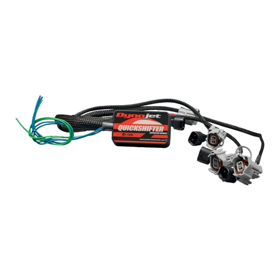
Quick Shifter Module
1
Installation Guide
2
Power Commander Decals
2
Dynojet Decals
1
Velcro
1
Alcohol swab
PLEASE READ ALL DIRECTIONS BEFORE STARTING INSTALLATION
QEM15
www.powercommander.com
2008-2012 Yamaha R6
2009-2012 Yamaha R1
2191 Mendenhall Drive North Las Vegas, NV 89081 (800) 992-4993 www.powercommander.com
I n s t a l l a t i o n I n s t r u c t i o n s
2009-2012 Yamaha R6/R1 - 1
Advertisement
Table of Contents

Related Manuals for Dynojet Quickshifter


Summary of Contents for Dynojet Quickshifter
- Page 1 PARTS LIST Quick Shifter Module Installation Guide Power Commander Decals Dynojet Decals 2008-2012 Yamaha R6 Velcro 2009-2012 Yamaha R1 Alcohol swab I n s t a l l a t i o n I n s t r u c t i o n s PLEASE READ ALL DIRECTIONS BEFORE STARTING INSTALLATION 2191 Mendenhall Drive North Las Vegas, NV 89081 (800) 992-4993 www.powercommander.com...
- Page 2 FIG.A Remove the main seat and the passenger seat. Lift the fuel tank up or remove. Mount the QEM in the tail section using the supplied velcro. Make sure to clean both surfaces with the alcohol swab before attaching. FIG.B Remove the 4 bolts the hold the battery bracket and run the QEM harness underneath it on the left side (Fig. B) FIG.C Unplug the 6 pin CLEAR connector that is behind the airbox on the left side (Fig. C). QEM15 www.powercommander.com 2009-2012 Yamaha R6/R1 - 2...
- Page 3 FIG.D Plug the QEM in-line of the stock wiring harness (Fig. D). Plug the wiring harness from the shift sensor switch into the matching connector of the QEM. • For the unit to function correctly the wires from the QEM must be wired correctly to the PCV. The BLUE wire goes to pin #4 and the GREEN wire goes to pin #5 4th hole from end 5th hole from end • To insert the wires into the PCV strip back about 10mm of the insulation from the wire. Using a paperclip (or similar) poke the hole of the PCV to pierce the foam. It may also be helpful to tin the wire with solder for a secure connection. • Remove the rubber seal on the back side of the PCV. Loosen the set screw of the corresponding hole and insert the wire into the PCV. Tighten the set screw. Pull on the wire to ensure it does not pull out. • Open the PCV control center software. Go to Power Commander Tools - Configure - Features Enables and Disables - Quick Shifter. Click on the box to enable the quickshifter feature. You can adjust kill times per gear by going to Mode - Kill times per gear. For this to function you must have the speed input connected to the PCV and gear position calibrated correctly (see PCV install guide). • Update your PCV to firmware version 1.8.8. Go to Power Commander Tools - Update firmware. The latest firmware can be found at http:// www.powercommander.com. • This QEM can only be used with a normally open circuit shift sensor switch. QEM15 www.powercommander.com 2009-2012 Yamaha R6/R1 - 3...
Need help?
Do you have a question about the Quickshifter and is the answer not in the manual?
Questions and answers