FireBird Enviromax Systems C20 Technical Manual
Condensing range.
for use with diesel 35 second gas oil
Hide thumbs
Also See for Enviromax Systems C20:
- Technical manual (68 pages) ,
- Technical manual (68 pages) ,
- Technical manual (68 pages)
Table of Contents
Advertisement
ENVIROMAX
CONDENSING RANGE
TE CHNI CA L M AN UAL
For use with Diesel 35 Second Gas Oil
TECHNICAL MANUAL INCLUDES
❯❯ END USER INSTRUCTIONS
❯❯ INSTALLER GUIDE
❯❯ COMMISSIONING
❯❯ SERVICING
❯❯ PARTS
Working towards a greener planet
This manual must remain with the end user on completion of installation
Advertisement
Table of Contents

Related Manuals for FireBird Enviromax Systems C20


Summary of Contents for FireBird Enviromax Systems C20
- Page 1 ENVIROMAX CONDENSING RANGE TE CHNI CA L M AN UAL For use with Diesel 35 Second Gas Oil TECHNICAL MANUAL INCLUDES ❯❯ END USER INSTRUCTIONS ❯❯ INSTALLER GUIDE ❯❯ COMMISSIONING ❯❯ SERVICING ❯❯ PARTS Working towards a greener planet This manual must remain with the end user on completion of installation...
-
Page 3: Table Of Contents
CONTENTS PAGE FOREWORD & INTRODUCTION TECHNICAL SPECIFICATIONS 2.1 System Boiler ..............................2.2 Kitchen (Basic) & Commercial Utility Boilers .............. 2.3 Slimline Systempac Boiler ......................... INSTALLATION IN NEW ZEALAND AND AUSTRALIA ..SAFETY ..................................END USER INSTRUCTIONS 5.1 Operating procedure ........................5.2 Thermostat Control &... -
Page 4: Foreword & Introduction
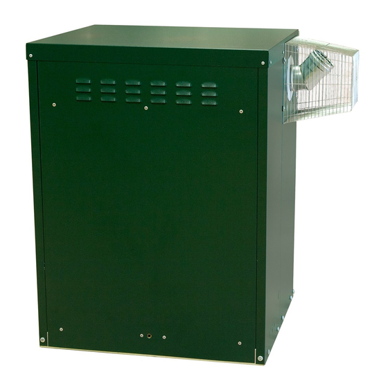
It is important that The Firebird Condensing Boiler is suitable for servicing should be conducted by a competent under floor heating provided the return engineer, such as one who is OFTEC trained temperature is above 40˚C. - Page 5 2.1 TECHNICAL SPECIFICATIONS - SYSTEM BOILER System C20, C26 & C35 System C44 Front View Side View Top View Front View Side View Top View Model Output Weight Dimensions(mm) Enviromax System C20 15-20 System C26 20-26 System C35 26-35 System C44 35-44 1048 Use of copper pipe is recommended for a minimum of 1 metre off the boiler.
-
Page 6: Technical Specifications
2.2 TECHNICAL SPECIFICATIONS - KITCHEN (BASIC) & COMMERCIAL UTILITY BOILERS Front View Side View Top View Model Output Weight Dimensions(mm) Enviromax Kitchen (Basic) C12/18 12-18 Kitchen (Basic) C44 35-44 1048 Kitchen (Basic) C58 44-58 1048 Kitchen (Basic) C73 58-73 1196 1024 Commercial Utility 80-100... - Page 7 2.3 TECHNICAL SPECIFICATIONS - SLIMLINE SYSTEMPAC BOILER Dimensions Model Output Weight Enviromax 20-26 Slimline Systempac C26 26-35 Slimline Systempac C35 Use of copper pipe is recommended for a minimum of 1 metre off the boiler. Boiler Model Heat Output 20-26 26-35 Max.
- Page 8 AS1691-1985 Domestic Oil fired Appliances Installation. Please ensure that the appliance is bolted to the floor for seismic restraint. Firebird recommend the use of Firebird coaxial flue systems to achieve room sealed operation. However, conventional flue systems are also suitable.
- Page 9 SAFETY HEALTH & SAFETY INFORMATION FUEL SPILLAGE Under the Consumer Protection Act 1987 (UK), Switch off all electrical and other ignition sources. section 6 of the Health and Safety Act 1974 (UK) and the Safety, Health and Welfare at Work Act 2005 Remove all contaminated clothing to safeguard (ROI), we are required to provide information on against fire risk and skin damage.
-
Page 10: System Boiler
5.1 END USER INSTRUCTIONS - OPERATING PROCEDURE Burner plug Mains supply light * Burner lock out light * High limit re-set button Burner plug Burner plug Temperature Temperature control control High Limit High limit Temperature re-set button re-set button control BURNER BURNER BURNER... -
Page 11: Thermostat Control & Burner Lockout
5.2 END USER INSTRUCTIONS - THERMOSTAT CONTROL & BURNER LOCKOUT WATER TEMPERATURE THERMOSTAT CONTROL Figure 1 Set at Max 80˚C Set at Mid 70˚C Set at Min 60˚C BURNER LOCKOUT (ALL MODELS) The boiler is factory fitted with a burner control box lockout safety feature which operates automatically if a fault occurs in the burners operation. -
Page 12: Guidelines
The flue terminal should be mounted so that it is • Firebird accepts no responsibility for failure of plastic separated from any combustible material forming a part of piping and fittings for whatever reason. -
Page 13: Positioning The Boilers
Sound levels must also be a consideration. Whilst Firebird Enviromax boilers are one of the quietest boilers on the market, some end users are particularly sensitive and the following points should be considered: 1. -
Page 14: Condensate Disposal
The condensate trap is located trap with water. at the base of the boiler. Condensate baffle and condensate trap Before switching on your Firebird condensing oil boiler check that: (1) The float & condensate drain baffle are in place. (2) That the condensate trap is primed. - Page 15 METHOD 2 - CONDENSATE PUMP IMPORTANT Firebird condensing boilers when in condensing mode extract more heat from the flue products and the resulting condensate which is mildly acidic needs to be drained from the boiler via a condensate pipe to the drainage system.
-
Page 16: Sealed System Heating Circuit
6.4 INSTALLATION - SEALED SYSTEM HEATING CIRCUIT SEALED HEATING CIRCUIT The system must comply with BS 7074 Part 1 and BS 5449 Part 1 with a maximum water temperature of 80˚C. * A manual reset overheat limit thermostat is located at the rear of the electrical control panel. - Page 17 6.4 INSTALLATION - SEALED SYSTEM HEATING CIRCUIT Nearest available stock size for additional vessel (b) Static head may be higher than calculated. In required, at 1 bar initial system pressure (taken from this case it is necessary to re-measure static above table) is 5 Litres.
- Page 18 Special attention should be given to existing supply before system pressure reaches safety valve heating systems where a Firebird boiler has operation point of 3 bar. (Say 2 to 2.5 bar).Vent system replaced an existing unit. Extra effort should be...
-
Page 19: Flue Regulations
450mm from painted eaves. Prevailing winds should be taken into account when siting a flue. FIREBIRD RECOMMENDS AS PER OFTEC RECOMMENDATIONS, THAT THE FLUE SHOULD BE A MINIMUM DISTANCE OF 1 METRE FROM OPENINGS SO THAT IT DOES NOT CAUSE A NUISANCE AND PERMITS THE DISPERSAL OF COMBUSTION PRODUCTS (SEE PAGE 18). - Page 20 6.5 INSTALLATION - FLUE REGULATIONS Clearances advised by BS 5410 Part 1: 2014 Regular Appliance (Open, Low Level Discharge and Balanced) Flue Termination Clearance The basic requirement with regard to flue positioning is that no hazard or nuisance is caused by the flue gases. Diagrams 20a and 20b show clearances advised by BS 5410 Part 1: 2014.
- Page 21 BALANCED FLUE BOILERS The Firebird boiler may be set for room-sealed flue operation using a Firebird condensing balanced flue kit. This kit does not draw combustion air from inside the room. It is drawn from outside, direct to the burner by an air pipe supplied with the boiler.
- Page 22 6.5 INSTALLATION - FLUE REGULATIONS Ventilation and Combustion Air Conventional Flue Boilers An adequate supply of combustion and ventilation air is essential for efficient and safe boiler operation and the openings for this should be positioned to cause least possible draught, with no possibility of being accidentally blocked.
-
Page 23: Ventilation & Combustion Air Requirements
6.6 INSTALLATION - VENTILATION & COMBUSTION AIR REQUIREMENTS FIREBIRD ENVIROMAX BALANCED FLUE SYSTEMS Vertical balanced flue kit - max flue length 6 m Low level balanced flue kit - max length 3 m Hign level balanced flue kit - max length 6 m Overall length must take into account bends where 45°... - Page 24 6.6 INSTALLATION - VENTILATION & COMBUSTION AIR REQUIREMENTS CONVENTIONAL FLUE SYSTEMS IMPORTANT The Firebird condensing boiler must not be installed with existing flue systems. A flue system suitable for wet flues must be used. If a flue system which is unsuitable is used it will invalidate the warranty.
- Page 25 6.6 INSTALLATION - VENTILATION & COMBUSTION AIR REQUIREMENTS It is necessary to ensure when the plumber is installing the A boiler that fails to operate correctly may require a plume flue that he: kit. This is because the flue gases are not able to disperse, causing the photocell to become dirty.
- Page 26 6.6 INSTALLATION - VENTILATION & COMBUSTION AIR REQUIREMENTS INSTALLATION INSTRUCTIONS SUPPLIED WITH ALL FLUE KITS CONDENSING BOILER CHIMNEY INSTALLATION Condensing Condensing Birdguard birdguard System 35 System 35 clamp plate clamp plate System 35 flexible liner System 35 flexible liner suitable for condensing suitable for condensing applications applications...
-
Page 27: Flue Assembly
6.7 INSTALLATION - FLUE ASSEMBLY SLIMLINE SYSTEMPAC... - Page 28 6.8.1 - INSTALLATION - WIRING - SYSTEM BOILER ELECTRICAL SUPPLY The boiler and controls require 230V 50Hz mains electric supply protected with a 5A fuse. The warranty on this product will be rendered void if damaged by power from a stand by electricity supply i.e. (generator). This appliance must be earthed.
- Page 29 6.8.2 INSTALLATION - WIRING - KITCHEN (BASIC) & COMMERCIAL UTILITY BOILERS ELECTRICAL SUPPLY The boiler and controls require 230V 50Hz mains electric supply protected with a 5A fuse. The warranty on this product will be rendered void if damaged by power from a stand by electricity supply i.e. (generator). This appliance must be earthed.
- Page 30 6.8.3 INSTALLATION - WIRING - SLIMLINE SYSTEMPAC BOILER ELECTRICAL SUPPLY The boiler and controls require 230V 50Hz mains electric supply protected with a 5A fuse. The warranty on this product will be rendered void if damaged by power from a stand by electricity supply i.e. (generator). This appliance must be earthed.
- Page 31 6.9 INSTALLATION - OIL SUPPLY DIESEL STORAGE TANK SITING FLEXIBLE OIL PIPE(S) Consult OFTEC manuals, AS1691 A flexible burner diesel hose is supplied with the boiler or Central Heating New Zealand Tank Guide. which must be wholly contained with in the appliance case.
- Page 32 6.9 INSTALLATION - OIL SUPPLY TWO PIPE SYSTEMS FIRE VALVES Where installation is such that the bottom of the tank is A fire valve is an essential part of the Diesel supply system. located below the Diesel burner pump, a two pipe system It should be capable of cutting off the flow of Diesel is required.
-
Page 33: Oil Supply
“lock-out” . competent, qualified engineer, preferably familiar with Firebird products. x The commissioning card should be completed and CHECKLIST FOR INSTALLING AND posted to Central Heating New Zealand within 28 days of installation and a copy should be retained COMMISSIONING A FIREBIRD BOILER by the commissioning engineer. - Page 34 • OFTEC forms CD10 and CD11. the dial - example: the factory setting for a Firebird C26 has a Danfoss .65 80° ES nozzle with a pump pressure The end user should be advised to: of 9 bar and air at 2.5. Set the air to 3 for the first start •...
-
Page 35: Servicing
Remove combustion access door for access to baffles necessary. Replace flexible diesel lines every 2 and to clean heat exchanger. years. Cleaning a Firebird condensing boiler: Combustion Check 1. Carry out a combustion analysis. 1. Remove all baffles, including the tubular baffles in 2. -
Page 36: 9.1 Burner - Settings
C100 The above settings were carried out on a Firebird condensing boiler with 2 metres of vertical balanced flue. The ambient air was averaging around 20˚C. Allowances should also be made for the viscosity of the oil and the tolerance of the nozzles. -
Page 37: G10 Blast Tube
9.2 BURNER - G10 BLAST TUBE APPLIES TO C58-C100 Boiler Burner Nozzle Pump Blast Tube Head Air Box RDB4.2 200/250K & C73 1.25 60 S 12.0 bar 11.5% Make sure the door of the Slimline Systempac is in place when setting the CO . -
Page 38: Specifications
9.3 BURNER - SPECIFICATIONS HYDRAULIC SYSTEM Burner Description WARNING One stage kerosene burner. • SINGLE PIPE The pump is designed to allow working with one pipe. The intake air temperature must not be over 70 °C. • TWO PIPE Burner with CE marking in conformity with EEC directives: In order to obtain two pipe working it is necessary to unscrew the EMC 89/336/CEE and Efficiency 92/42/EEC. -
Page 39: Fault Finding
9.4 BURNER - FAULT FINDING... - Page 40 10.1 - PARTS & BAFFLES - SYSTEM BOILER...
- Page 41 10.1 - PARTS & BAFFLES - SYSTEM BOILER Description Boiler Shell 312133 312133 312133 311783 Heat Deflector 210904 210904 210904 211643 Tube Baffle 1 Way 110908 (5 off ) 110908 (5 off ) 110908 (5 off ) 111502 (8 off ) Tube Baffle 4 Way 110907 (4 off...
-
Page 42: Parts & Baffles
10.2 PARTS & BAFFLES - KITCHEN (BASIC) & COMMERCIAL UTILITY BOILERS... - Page 43 10.2 PARTS & BAFFLES - KITCHEN (BASIC) & COMMERCIAL UTILITY BOILERS No. Description C12-18 C20/26 C100 1 Boiler Shell 312808 312026 312026 311634 311634 311481 312422 2 Heat Deflector 212810 210904 210904 211643 211643 211500 212420 3 Tube Baffle 1 Way 110908 (7 off...
- Page 44 10.3 - PARTS & BAFFLES - SLIMLINE SYSTEMPAC BOILER...
-
Page 45: Slimline Systempac Boiler
10.3 - PARTS & BAFFLES - SLIMLINE SYSTEMPAC BOILER Description Slimline Heatpac C20, C26, C35 Slimline Systempac C20, C26, C35 Boiler Shell 312134 312733 Heat Deflector 210904 210904 Tube Baffle 1 Way 110908 (5 off ) 110908 (5 off ) Tube Baffle 4 Way 110907 (4 off... - Page 46 10.4 - PARTS & BAFFLES - BURNER DIESEL - LIGHT OIL BURNERS RDB2.2R FIREBIRD 70D 3515105 744T1R COD. TIPO/TYPE/TYP RDB2.2R FIREBIRD 90D 3515305 744T3R COD. TIPO/TYPE/TYP RDB2.2R FIREBIRD 120D 3515505 744T5R COD. TIPO/TYPE/TYP RDB2.2R FIREBIRD 150D 3515506 744T5R COD. TIPO/TYPE/TYP •...
- Page 47 10.4 - PARTS & BAFFLES - BURNER DIESEL - LIGHT OIL BURNERS RDB3 FIREBIRD 150K 3748965 489 T50 COD. TYPE RDB4 FIREBIRD 200K 3748965 488 T50 COD. TYPE RDB4.2 FIREBIRD C58/200K 3748965 490 T61 COD. TYPE COD. DESCRIPTION COD. DESCRIPTION 3008637 •...
-
Page 48: Standards & Regulations
STANDARDS & REGULATIONS STANDARDS & REGULATIONS PRE- INSTALLATION CHECKS To ensure the highest standards of installation & The installer should also be aware of his/her safety, it is important that the boiler be installed in responsibilities under The Health and Safety at Work compliance with the following regulations where Act. -
Page 49: Terms & Conditions Of Warranty
Consumable components, the nozzles and the oil hose unqualified persons. are excluded. 8. Firebird will not accept any liability in respect of any defect occurring to the product due to limescale build-up and or low return water temperature. 9. The warranty programme extends to reasonable... -
Page 50: Service Record
SERVICE RECORD Service Record All Information recorded hereunder should also be included in the Engineer’s own filed service reports. It is recommended that the boiler be serviced at least once a year and the details recorded below. The Engineer should advise the end user. SERVICE SERVICE SERVICE... -
Page 51: Commissioning Card
COMMISSIONING CARD The commissioning card below must be returned to Central Heating New Zealand within 28 days of installation to validate the warranty. COMMISSIONING CARD & TEAR OFF HERE RETURN TO THE APPROPRIATE ADDRESS END USER (In block capitals) INSTALLER (In block capitals) ........................... - Page 52 Tel: + (0) 64 3357 1233 www.centralheating.co.nz © Copyright applies to all FIREBIRD products. Our policy is one of continual development and we therefore reserve the right to change without prior notice the specification of our products at any time and be without obligation to make similar changes in products previously produced.
Need help?
Do you have a question about the Enviromax Systems C20 and is the answer not in the manual?
Questions and answers