Table of Contents
Advertisement
Advertisement
Table of Contents

Related Manuals for Xilinx ZCU104


Summary of Contents for Xilinx ZCU104
- Page 1 ZCU104 Evaluation Board User Guide UG1267 (v1.1) October 9, 2018...
-
Page 2: Revision History
GTR_REF_CLK_USB3 frequency to 26 MHz. In Table 3-24, replaced LVCMOS12 and LVCMOS18 with LVCMOS33. Appendix B: Updated appendix title and Overview. Removed ZCU104 Board Constraints File section. Appendix C: Updated Overview. Appendix D: Added Zynq UltraScale+ MPSoC Data Sheet: DC and AC Switching Characteristics (DS925) to References. -
Page 3: Table Of Contents
GEM3 Ethernet (MIO 64-77) ..............46 ZCU104 Board User Guide Send Feedback UG1267 (v1.1) October 9, 2018... - Page 4 Xilinx Resources ........
-
Page 5: Chapter 1: Introduction
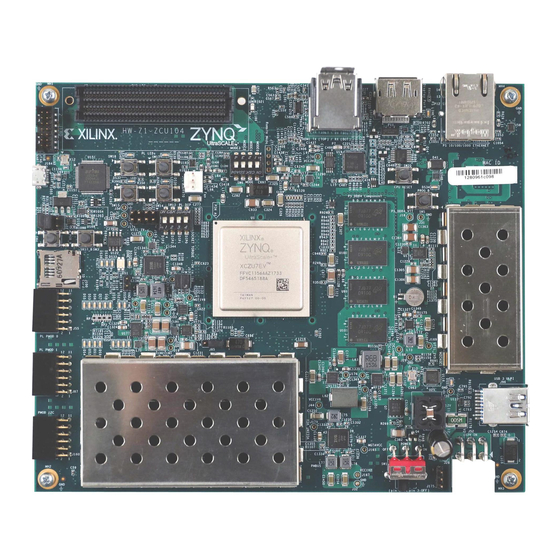
DDR4 memory interfaces, an FMC expansion port, multi-gigabit per second serial transceivers, a variety of peripheral interfaces, and FPGA fabric for customized designs. The ZCU104 reVISION package provides out-of-box SDSoC™ software development flow with OpenCV libraries, machine learning framework, and live sensor support. -
Page 6: Block Diagram
Chapter 1: Introduction Block Diagram The ZCU104 board block diagram is shown in Figure 1-1. X-Ref Target - Figure 1-1 FMC LPC UART2 UART / I2C PMOD0/1 PL I2C1 QSPI SD 3.0 HDMI Control Bank 88 Bank 68 Bank 67... -
Page 7: Board Features
Chapter 1: Introduction Board Features The ZCU104 evaluation board features are listed here. Detailed information for each feature is provided in Component Descriptions in Chapter • XCZU7EV-2, FFVC1156 package • PL V for range in data sheet CCINT • Rectangular form factor for benchtop use •... - Page 8 Operational status LEDs (power status, INIT, DONE, PG, DDR power good) • Power management The ZCU104 provides a rapid prototyping platform for the embedded vision low cost (EVLC) market using the XCZU7EV-2FFVC1156 device. The ZU7EV contains PS hard block peripherals exposed through the multi-use I/O (MIO) interface and several FPGA programmable logic (PL), high-density (HD), and high-performance (HP) banks.
-
Page 9: Board Specifications
A 3D model of this board is not available. Note: ZCU104 board documentation for XDC listing, schematics, layout files, board outline drawings, etc. Environmental Temperature Operating: 0°C to +45°C Storage: -25°C to +60°C ZCU104 Board User Guide Send Feedback UG1267 (v1.1) October 9, 2018 www.xilinx.com... -
Page 10: Operating Voltage
Chapter 1: Introduction Humidity 10% to 90% non-condensing Operating Voltage +12 V ZCU104 Board User Guide Send Feedback UG1267 (v1.1) October 9, 2018 www.xilinx.com... -
Page 11: Chapter 2: Board Setup And Configuration
Always refer to the schematic, layout, and XDC files of the specific ZCU104 version of interest for such details. The ZCU104 board can be damaged by electrostatic discharge (ESD). Follow standard ESD CAUTION! prevention measures when handling the board. - Page 12 Put the adapter down only on an antistatic surface such as the bag supplied in your kit. • If you are returning the adapter to Xilinx Product Support, place it back in its antistatic bag immediately. X-Ref Target - Figure 2-1...
- Page 13 Chapter 2: Board Setup and Configuration Table 2-1: ZCU104 Board Component Locations Callout Schematic Ref. Des. Feature ([B] = bottom of board) Notes Number Page Zynq UltraScale+ XCZU7EV MPSoC XCZU7EV-2FFVC1156 3–18 with Radian fan sink FA35+K52B+T725 PS-Side: DDR4 Component Memory, Micron MT40A256M16GE-083E 24–27...
- Page 14 Chapter 2: Board Setup and Configuration Table 2-1: ZCU104 Board Component Locations (Cont’d) Callout Schematic Ref. Des. Feature ([B] = bottom of board) Notes Number Page Switches C&K 1201M2S3AQE2 Power on/off slide switch) Switches MOLEX 39-30-1060 (2 x 3 mini-fit receptacle)
-
Page 15: Default Jumper And Switch Settings
Chapter 2: Board Setup and Configuration Default Jumper and Switch Settings Figure 2-1 shows the ZCU104 board jumper header and DIP switch locations. Each numbered component shown in the figure is keyed to Table 2-2 (for default jumper settings) or Table 2-3 (for default switch settings). -
Page 16: Switches
Vivado®, SDK, or third-party tools can establish a JTAG connection to the Zynq UltraScale+ MPSoC device through the FT4232 Quad USB to multipurpose UART (U151) with micro-USB connector (J164). ZCU104 Board User Guide Send Feedback UG1267 (v1.1) October 9, 2018... -
Page 17: Quad Spi
3. Either power-cycle or press the power-on reset (POR) pushbutton SW4. SW4 is callout 20 Figure 2-1. See the Zynq UltraScale+ MPSoC Technical Reference Manual (UG1085) [Ref 2] for more information about Zynq UltraScale+ MPSoC configuration options. ZCU104 Board User Guide Send Feedback UG1267 (v1.1) October 9, 2018 www.xilinx.com... -
Page 18: Chapter 3: Board Component Descriptions
Component Descriptions Zynq UltraScale+ XCZU7EV MPSoC [Figure 2-1, callout 1] The ZCU104 board is populated with the Zynq UltraScale+ XCZU7EV-2FFVC1156 MPSoC, which combines a powerful processing system (PS) and programmable logic (PL) in the ® ® same device. The PS in a Zynq UltraScale+ MPSoC features the Arm... - Page 19 0.876 For -1LI and -2LE (V = 0.72V) devices: CCINT 0.698 0.720 0.742 CCINT PL internal supply voltage. For -3E devices: PL internal supply voltage. 0.873 0.900 0.927 ZCU104 Board User Guide Send Feedback UG1267 (v1.1) October 9, 2018 www.xilinx.com...
- Page 20 AES-GCM Processor System PCIe DDRC (DDR4/3/3L, LPDDR3/4) 128 KB RAM To ACP Gen4 32-bit/64-bit Battery Low Power Full Power Power 64-bit 128-bit X16387-012618 Figure 3-1: Top-Level Block Diagram ZCU104 Board User Guide Send Feedback UG1267 (v1.1) October 9, 2018 www.xilinx.com...
- Page 21 For additional information on Zynq UltraScale+ MPSoC devices, see the Zynq UltraScale+ MPSoC Data Sheet: Overview (DS891) [Ref 1]. See the Zynq UltraScale+ MPSoC Technical Reference Manual (UG1085) [Ref 2] for more information about Zynq UltraScale+ MPSoC configuration options. ZCU104 Board User Guide Send Feedback UG1267 (v1.1) October 9, 2018 www.xilinx.com...
-
Page 22: Encryption Key Battery Backup Circuit
Chapter 3: Board Component Descriptions Encryption Key Battery Backup Circuit The XCZU7EV MPSoC U1 implements bit stream encryption key technology. The ZCU104 board provides the encryption key backup battery circuit shown in Figure 3-2. X-Ref Target - Figure 3-2 X20247-013018 Figure 3-2: Encryption Key Backup Circuit The Seiko TS518FE rechargeable 1.5V lithium button-type battery B1 is soldered to the... - Page 23 Chapter 3: Board Component Descriptions I/O Voltage Rails The XCZU7EV MPSoC PL I/O bank voltages on the ZCU104 board are listed in Figure 3-2. Table 3-2: I/O Voltage Rails XCZU7EV Power Net Name Voltage Connected To PL Bank 28 1.8V...
-
Page 24: Ps-Side: Ddr4 Component Memory
° DDR4-2400 ° The ZCU104 XCZU7EV FFVC MPSoC PS DDR interface performance is documented in the Zynq UltraScale+ MPSoC Data Sheet: DC and AC Switching Characteristics (DS925) [Ref The DDR4 0.6V VTT termination voltage is supplied from sink-source regulator U178. The... - Page 25 DQL6 AK24 DDR4_DQ23 DQL7 AH28 DDR4_DQ24 DQU0 AH27 DDR4_DQ25 DQU1 AJ27 DDR4_DQ26 DQU2 AK27 DDR4_DQ27 DQU3 AL26 DDR4_DQ28 DQU4 AL27 DDR4_DQ29 DQU5 AH29 DDR4_DQ30 DQU6 AL28 DDR4_DQ31 DQU7 ZCU104 Board User Guide Send Feedback UG1267 (v1.1) October 9, 2018 www.xilinx.com...
- Page 26 DDR4_DQ55 DQL7 AA30 DDR4_DQ56 DQU0 DDR4_DQ57 DQU1 AA31 DDR4_DQ58 DQU2 DDR4_DQ59 DQU3 DDR4_DQ60 DQU4 DDR4_DQ61 DQU5 DDR4_DQ62 DQU6 DDR4_DQ63 DQU7 AN24 DDR4_DM0 DML_B/DBIL_B U101 AM29 DDR4_DM1 DMU_B/DBIU_B U101 ZCU104 Board User Guide Send Feedback UG1267 (v1.1) October 9, 2018 www.xilinx.com...
- Page 27 U2,U99-U101 AF28 DDR4_A16_RAS_B RAS_B/A16 U2,U99-U101 AG28 DDR4_A15_CAS_B CAS_B_A15 U2,U99-U101 AG29 DDR4_A14_WE_B WE_B/A14 U2,U99-U101 AE25 DDR4_ACT_B ACT_B U2,U99-U101 AB26 DDR4_ALERT_B ALERT_B U2,U99-U101 AA26 DDR4_PAR U2,U99-U101 AD26 DDR4_RESET_B RESET_B U2,U99-U101 ZCU104 Board User Guide Send Feedback UG1267 (v1.1) October 9, 2018 www.xilinx.com...
- Page 28 U2,U99-U101 R156 P/D DDR4_TEN U2,U99-U101 The ZCU104 board DDR4 64-bit component PS memory interface adheres to the constraints guidelines documented in the “PCB Guidelines for DDR4” section of UltraScale Architecture PCB Design User Guide (UG583) [Ref 4]. The ZCU104 DDR4 PS component interface is a 40Ω...
-
Page 29: Pl-Side: Ddr4 Sodimm Socket
° DDR4-2666 ° The ZCU104 XCZU7EV FFVC MPSoC PL DDR interface performance is documented in the Zynq UltraScale+ MPSoC Data Sheet: DC and AC Switching Characteristics (DS925) [Ref The DDR4 0.6V VTT termination voltage is supplied from sink-source regulator U177. The... - Page 30 AL16 DDR4_SODIMM_DQ23 POD12_DCI DQ23 AN16 DDR4_SODIMM_DQ24 POD12_DCI DQ24 AN17 DDR4_SODIMM_DQ25 POD12_DCI DQ25 AP15 DDR4_SODIMM_DQ26 POD12_DCI DQ26 AP16 DDR4_SODIMM_DQ27 POD12_DCI DQ27 AN18 DDR4_SODIMM_DQ28 POD12_DCI DQ28 AM18 DDR4_SODIMM_DQ29 POD12_DCI DQ29 ZCU104 Board User Guide Send Feedback UG1267 (v1.1) October 9, 2018 www.xilinx.com...
- Page 31 AM23 DDR4_SODIMM_DQ57 POD12_DCI DQ57 AP23 DDR4_SODIMM_DQ58 POD12_DCI DQ58 AN22 DDR4_SODIMM_DQ59 POD12_DCI DQ59 AP22 DDR4_SODIMM_DQ60 POD12_DCI DQ60 AP21 DDR4_SODIMM_DQ61 POD12_DCI DQ61 AN19 DDR4_SODIMM_DQ62 POD12_DCI DQ62 AM19 DDR4_SODIMM_DQ63 POD12_DCI DQ63 ZCU104 Board User Guide Send Feedback UG1267 (v1.1) October 9, 2018 www.xilinx.com...
- Page 32 CK1_C/NF DDR4_SODIMM_CK1_C DIFF_SSTL12_DCI CK1_T/NF AB13 DDR4_SODIMM_CKE0 SSTL12_DCI CKE0 AL13 DDR4_SODIMM_CKE1 SSTL12_DCI CKE1 AF10 DDR4_SODIMM_ODT0 SSTL12_DCI ODT0 AK13 DDR4_SODIMM_ODT1 SSTL12_DCI ODT1 AF11 DDR4_SODIMM_RAS_B SSTL12_DCI RAS_N/A16 AE12 DDR4_SODIMM_CAS_B SSTL12_DCI CAS_N/A15 ZCU104 Board User Guide Send Feedback UG1267 (v1.1) October 9, 2018 www.xilinx.com...
-
Page 33: Psmio
AF12 DDR4_SODIMM_RESET_B LVCMOS12 RESET_N The ZCU104 board PL DDR4 SODIMM interface adheres to the constraints guidelines documented in the “PCB Guidelines for DDR4” section of UltraScale Architecture PCB Design User Guide (UG583) [Ref 4]. The PL DDR4 SODIMM interface is a 40Ω impedance implementation. -
Page 34: Quad Spi Flash Memory (Mio 0-5)
Table 3-6: Quad SPI Flash Memory Component Connections to MPSoC U1 Quad SPI U119 (LWR), U120 (UPR) XCZU7EV (U1) Pin Net Name Pin # Pin Name MIO4_QSPI_LWR_DQ0 MIO1_QSPI_LWR_DQ1 MIO2_QSPI_LWR_DQ2 DQ2_WP_B MIO3_QSPI_LWR_DQ3 DQ3_RST_HOLD_B MIO0_QSPI_LWR_CLK MIO5_QSPI_LWR_CS_B ZCU104 Board User Guide Send Feedback UG1267 (v1.1) October 9, 2018 www.xilinx.com... -
Page 35: Usb 3.0 Transceiver And Usb 2.0 Ulpi Phy
Figure 3-3). A USB cable is supplied in the ZCU104 evaluation kit (standard-A connector to host computer, micro-B connector to ZCU104 board connector J96). The USB3320 is a high-speed USB 2.0 PHY supporting the UTMI+ low pin interface (ULPI) interface standard. The ULPI standard defines the interface between the USB controller IP and the PHY device, which drives the physical USB bus. - Page 36 2, which turns on LED DS51 if over current or thermal shutdown conditions are detected. DS51 is located in the U116 circuit area near pushbutton SW4 (Figure 2-1, callout 20). ZCU104 Board User Guide Send Feedback UG1267 (v1.1) October 9, 2018 www.xilinx.com...
-
Page 37: Sd Card Interface
This interface is used for the SD boot mode and supports SD3.0 access post boot. SD Card Interface [Figure 2-1, callout 6] The ZCU104 board includes a secure digital input/output (SDIO) interface to provide access to general purpose non-volatile SDIO memory cards and peripherals. See the SanDisk Corporation [Ref 13]... - Page 38 Chapter 3: Board Component Descriptions Figure 3-5 shows the connections of the SD card interface on the ZCU104 board. X-Ref Target - Figure 3-5 X20252-013018 Figure 3-5: SD Card Interface Table 3-8 lists the SD card interface connections to the XCZU7EV MPSoC.
-
Page 39: Programmable Logic Jtag Programming Options
Chapter 3: Board Component Descriptions Programmable Logic JTAG Programming Options [Figure 2-1, callouts 7 and 25] The ZCU104 board JTAG chain is shown in Figure 3-6. X-Ref Target - Figure 3-6 U151 FT4232 J164 U165 JTAG 1.8V SPST Bus Switch N.C. - Page 40 Chapter 3: Board Component Descriptions X-Ref Target - Figure 3-7 X20253-013018 Figure 3-7: M.2 Connector U170 ZCU104 Board User Guide Send Feedback UG1267 (v1.1) October 9, 2018 www.xilinx.com...
- Page 41 ADD_IN CARD KEY M ADD_IN CARD KEY M Reserved for MGFG_CLOCK Reserved for MGFG_DATA ALERT# (O) (0/1.8V) SMB_DATA (I/O) (0/1.8V) SMB_CLK (I/O) (0/1.8V) DEVSLP (I) 3.3V 3.3V 3.3V 3.3V DAS/DSS (I/O) ZCU104 Board User Guide Send Feedback UG1267 (v1.1) October 9, 2018 www.xilinx.com...
- Page 42 Table 3-9: M.2 Connector U170 Pinout (Cont’d) Signal 3.3V 3.3V PEDET (GND-SATA) ADD_IN CARD KEY M ADD_IN CARD KEY M ADD_IN CARD KEY M ADD_IN CARD KEY M SATA-A+ SATA-A- SATA-B+ SATA-B- ZCU104 Board User Guide Send Feedback UG1267 (v1.1) October 9, 2018 www.xilinx.com...
- Page 43 Chapter 3: Board Component Descriptions Table 3-9: M.2 Connector U170 Pinout (Cont’d) Signal The M.2 adapter tie-offs as implemented on the ZCU104 board are listed in Table 3-10. Table 3-10: M.2 U170 Connector Tie-offs M.2 Signal Name ZCU104 Tie-Off U170 Pin...
-
Page 44: Clock Generation
Chapter 3: Board Component Descriptions Clock Generation The ZCU104 board provides an IDT8T49N287 FemtoClock® NG octal universal frequency translator (U182) clock generator. Table 3-12 lists the frequency for each clock. Table 3-12: Clock Sources IDT8T49N287 U182 Clock (Net) Name Frequency... -
Page 45: Idt8T49N287 Femtoclock Ng Octal Universal Frequency Translator
I2C bus. The clock circuit is shown in Figure 3-8. X-Ref Target - Figure 3-8 X20254-013018 Figure 3-8: IDT8T49N287 Clock Generator For more details, see the IDT8T49N287A data sheet [Ref 21]. ZCU104 Board User Guide Send Feedback UG1267 (v1.1) October 9, 2018 www.xilinx.com... -
Page 46: Gem3 Ethernet (Mio 64-77)
Figure 3-9: Ethernet Block Diagram 10/100/1000 MHz Tri-Speed Ethernet PHY [Figure 2-1, callout 9] The ZCU104 board uses the TIDP83867IRPAP Ethernet RGMII PHY [Ref 16] (U98) for Ethernet communications at 10 Mb/s, 100 Mb/s, or 1000 Mb/s. The board supports RGMII mode only. - Page 47 MAX16025 U22 MPSoC PS-side POR reset device (PS_POR_B) or the I2C0 connected U97 TCA6416A I/O expander pin 10 port P06 (GEM3_EXP_RESET_B). X-Ref Target - Figure 3-10 X20255-013018 Figure 3-10: Ethernet PHY Reset Circuit ZCU104 Board User Guide Send Feedback UG1267 (v1.1) October 9, 2018 www.xilinx.com...
- Page 48 MDIO/MDC. LED_2 is assigned to the activity indicator (ACT) and LED_0 indicates link established. For more Ethernet PHY details, see the TI DS83867 data sheet [Ref 16]. ZCU104 Board User Guide Send Feedback UG1267 (v1.1) October 9, 2018 www.xilinx.com...
- Page 49 LED_2 is the RJ-45 P12 bezel left-side green LED, TX/RX activity indicator. • LED_1 is the green DS27 LED, mounted on the ZCU104 board top between the display port connector P11 and the Ethernet RJ-45 connector P12, indicates the 1000BASE-T link is established.
-
Page 50: I2C1 (Mio 16-17)
J160 IRPS5401_ALERT_B SDA 7,8 SDA/ HDMI_8T49N241_INT_ALM SCL 5,6 MAX6643_OT_B 2x6 Male Pin Hdr. MAX6643_FANFAIL_B VCC12_INA226_ALERT IIC_MUX_RESET_B GEM3_EXP_RESET_B FMC_LPC_PRSNT_M2C_B NOT CONNECTED 0x20 P10-P17 X20117-021218 Figure 3-12: I2C1 Bus Topology ZCU104 Board User Guide Send Feedback UG1267 (v1.1) October 9, 2018 www.xilinx.com... - Page 51 U97 I2C1 Expander Schematic Net Name Target Device Pin (Addr 0x20) Port IRP5401_ALERT_B U179.17 HDMI_8T49N241_INT_ALM U181.29 MAX6643_OT_B U128.9 MAX6643_FANFAIL_B U128.4 VCC12_INA226_ALERT U183.3 IIC_MUX_RESET_B U34.3 GEM3_EXP_RESET_B U169.2 FMC_LPC_PRSNT_M2C_B J5.H2 ZCU104 Board User Guide Send Feedback UG1267 (v1.1) October 9, 2018 www.xilinx.com...
-
Page 52: Ft4232Hl Usb Uart Interface (Mio 18-21)
FT4232HL USB UART Interface (MIO 18-21) [Figure 2-1, callout 7] The FT4232HL U151 quad USB-UART on the ZCU104 board provides three level-shifted UART connections through the single micro-AB USB connector J164. • Channel A is configured to support the JTAG chain. -
Page 53: Uart0 (Mio 18-19)
Table 3-19: XCZU7EV U1 PS-side MIO 18, 19 to FT4232HL U151 Connections via L/S U161 FT4232HL U151 XCZU7EG U1 Schematic Net Name Pin Name Pin# Pin Name Pin # PS_MIO18 UART0_TXD_MIO18_RXD BDBUS1 PS_MIO19 UART0_RXD_MIO19_TXD BDBUS0 ZCU104 Board User Guide Send Feedback UG1267 (v1.1) October 9, 2018 www.xilinx.com... -
Page 54: Uart1 (Mio 20-21)
TXS0104E level-translator U33 and TI SN65HVD232 CAN-bus transceiver U122 to the 0.1 inch centered 8-pin male header J98 as shown in Figure 3-14. X-Ref Target - Figure 3-14 X20257-013018 Figure 3-14: PS-Side CAN Bus Circuit ZCU104 Board User Guide Send Feedback UG1267 (v1.1) October 9, 2018 www.xilinx.com... -
Page 55: Dpaux (Mio 27-30)
3-21). The DisplayPort circuit is shown in Figure 3-15. Table 3-21: DPAUX/MIO Connections Level Shifter U114 XCZU7EV (U1) Pin Net Name Pin Name Pin # MIO30_DP_AUX_IN MIO29_DP_OE MIO28_DP_HPD MIO27_DP_AUX_OUT ZCU104 Board User Guide Send Feedback UG1267 (v1.1) October 9, 2018 www.xilinx.com... - Page 56 Chapter 3: Board Component Descriptions X-Ref Target - Figure 3-15 X16547-013018 Figure 3-15: DisplayPort Circuit ZCU104 Board User Guide Send Feedback UG1267 (v1.1) October 9, 2018 www.xilinx.com...
-
Page 57: Hdmi Video Output
[Figure 2-1, callouts 10 and 11] The ZCU104 board provides an HDMI® video output using a TI SN65DP159RGZ re-timer at U94. The output is provided on a TE Connectivity 1888811-1 right-angle dual-stacked HDMI type-A receptacle at P7. The SN65DP159RGZ device is a dual mode DisplayPort to transition-minimized differential signal (TMDS) re-timer supporting digital video interface (DVI) 1.0, HDMI 1.4b, and 2.0 output signals. - Page 58 Chapter 3: Board Component Descriptions X-Ref Target - Figure 3-16 Figure 3-16: HDMI Interface Block Diagram ZCU104 Board User Guide Send Feedback UG1267 (v1.1) October 9, 2018 www.xilinx.com...
- Page 59 Chapter 3: Board Component Descriptions X-Ref Target - Figure 3-17 X16535-020118 Figure 3-17: HDMI TX Interface Circuit X-Ref Target - Figure 3-18 X20258-020218 Figure 3-18: HDMI RX Interface Circuit ZCU104 Board User Guide Send Feedback UG1267 (v1.1) October 9, 2018 www.xilinx.com...
- Page 60 TMDS181IRGZT (U19) HDMI_RX1_C_N OUT_D1N Wired to HDMI HDMI_RX2_C_P OUT_D2P bottom port(P7) HDMI_RX2_C_N OUT_D2N HDMI_RX_CLK_C_P OUT_CLKP HDMI_RX_CLK_C_N OUT_CLKN HDMI_RX_HPD LVCMOS33 HPD_SNK HDMI_RX_PWR_DET LVCMOS33 HDMI_CTL_SCL LVCMOS33 SCL_CTL HDMI_CTL_SDA LVCMOS33 SDA_CTL ZCU104 Board User Guide Send Feedback UG1267 (v1.1) October 9, 2018 www.xilinx.com...
-
Page 61: Hdmi Clock Recovery
HDMI Clock Recovery [Figure 2-1, callout 29] The ZCU104 board includes an IDT 8T49N241 jitter attenuator U181. The 8T49N241 has one fractional feedback phase-locked loop (PLL) that can be used as a jitter attenuator and frequency translator. The FPGA can output the RX recovered clock to a differential I/O pair on I/O bank 67 (HDMI_REC_CLOCK_P, pin G14 and HDMI_REC_CLOCK_N, pin F13) for jitter attenuation. -
Page 62: User Pmod Gpio Connectors
User PMOD GPIO Connectors [Figure 2-1, callout 14] The ZCU104 evaluation board supports two PMOD GPIO headers J55 (right-angle female) and J87 (vertical male). The 3.3V PMOD nets are wired to the XCZU7EV device U1 bank 87. Figure 3-20 shows the GPIO PMOD headers J55 and J87. - Page 63 J55.6 PMOD0_7 LVCMOS33 J55.8 PMOD1_0 LVCMOS33 J87.1 PMOD1_1 LVCMOS33 J87.3 PMOD1_2 LVCMOS33 J87.5 PMOD1_3 LVCMOS33 J87.7 PMOD1_4 LVCMOS33 J87.2 PMOD1_5 LVCMOS33 J87.4 PMOD1_6 LVCMOS33 J87.6 PMOD1_7 LVCMOS33 J77.8 ZCU104 Board User Guide Send Feedback UG1267 (v1.1) October 9, 2018 www.xilinx.com...
-
Page 64: User I2C1 Receptacle
Chapter 3: Board Component Descriptions User I2C1 Receptacle [Figure 2-1, callout 21] The ZCU104 evaluation board supports a PMOD 2X6 receptacle (right-angle female) J160. Figure 3-21 shows the I2C1 PMOD receptacle J160. The I2C1 nets are a branch of the I2C1 main bus (see Figure 3-11, page 49). - Page 65 Figure 3-24 show the GPIO circuits. Table 3-24 lists the GPIO connections to XCZU7EV U1 3.3V bank 88. X-Ref Target - Figure 3-22 X20261-020118 Figure 3-22: GPIO LEDs ZCU104 Board User Guide Send Feedback UG1267 (v1.1) October 9, 2018 www.xilinx.com...
- Page 66 Chapter 3: Board Component Descriptions X-Ref Target - Figure 3-23 X20262-020118 Figure 3-23: GPIO Pushbutton Switches ZCU104 Board User Guide Send Feedback UG1267 (v1.1) October 9, 2018 www.xilinx.com...
- Page 67 SW20.3 GPIO DIP SW (Active High) GPIO_DIP_SW0 LVCMOS33 SW13.8 GPIO_DIP_SW1 LVCMOS33 SW13.7 GPIO_DIP_SW2 LVCMOS33 SW13.6 GPIO_DIP_SW3 LVCMOS33 SW13.5 Notes: 1. LEDs are driven through the U163 SN74AVC4T245 buffer. ZCU104 Board User Guide Send Feedback UG1267 (v1.1) October 9, 2018 www.xilinx.com...
-
Page 68: Power And Status Leds
UTIL_1V13_PG Green UTIL_1V13 1.13 VDC power on DS51 USB3 MIC2544 U121 FLG Green PS USB 3.0 ULPI VBUS power error DS53 UTIL_5V0_PGOOD Green UTIL_5V0 5 VDC power on ZCU104 Board User Guide Send Feedback UG1267 (v1.1) October 9, 2018 www.xilinx.com... - Page 69 Zynq UltraScale+ MPSoC configuration pins. Figure 3-25 shows the power and status LEDs area of the board. X-Ref Target - Figure 3-25 X20118-012618 Figure 3-25: Power and Status LEDs ZCU104 Board User Guide Send Feedback UG1267 (v1.1) October 9, 2018 www.xilinx.com...
-
Page 70: Gth Transceivers
Quads. The reference clock for a Quad can be sourced from the Quad above or the Quad below the GTH Quad of interest. There are five GTH Quads on the ZCU104 board with connectivity as listed here: Quad 223: •... - Page 71 Chapter 3: Board Component Descriptions GTH transceiver interface assignments on the ZCU104 are shown in Figure 3-26. X-Ref Target - Figure 3-26 BANK 223 BANK 226 MGT_223_0 NOT CONNECTED MGT_226_0 NOT CONNECTED NOT CONNECTED MGT_223_1 MGT_226_1 NOT CONNECTED NOT CONNECTED...
- Page 72 Not connected MGTHRXP2 Not connected MGTHRXN2 Not connected MGTHTXP3 Not Connected MGTHTXN3 Not Connected MGTHRXP3 Not Connected MGTHRXN3 Not Connected MGTREFCLK0P FMC_LPC_GBTCLK0_M2C_C_P GBTCLK0_M2C_P FMC LPC J5 MGTREFCLK0N FMC_LPC_GBTCLK0_M2C_C_N GBTCLK0_M2C_N ZCU104 Board User Guide Send Feedback UG1267 (v1.1) October 9, 2018 www.xilinx.com...
- Page 73 FMC_LPC_DP0_M2C_N DP4_M2C_N MGTREFCLK0P HDMI_8T49N241_OUT_C_N 8T49N241 U181 MGTREFCLK0N HDMI_8T49N241_OUT_C_P MGTREFCLK1P HDMI_RX_CLK_C_P OUT_CLKP TMDS181IR U19 MGTREFCLK1N HDMI_RX_CLK_C_N OUT_CLKN Notes: 1. Series capacitor coupled. 2. MGT connections I/O standard not applicable. ZCU104 Board User Guide Send Feedback UG1267 (v1.1) October 9, 2018 www.xilinx.com...
-
Page 74: Ps-Side: Gtr Transceivers
The PS-side GTR transceiver bank 505 supports two DisplayPort transmit channels, USB (3.0) and SATA, as shown in Figure 3-27. X-Ref Target - Figure 3-27 X20265-020118 Figure 3-27: PS-GTR Lane Assignments ZCU104 Board User Guide Send Feedback UG1267 (v1.1) October 9, 2018 www.xilinx.com... - Page 75 SSTXP PS_MGTRTXN2 GT2_USB0_TX_N SSTXN USB J96 PS_MGTRRXP2 GT2_USB0_RX_P SSRXP PS_MGTRRXN2 GT2_USB0_RX_N SSRXN PS_MGTRTXP3 GT3_SATA1_TX_P SATA_A_P PS_MGTRTXN3 GT3_SATA1_TX_N SATA_A_N M.2 U170 PS_MGTRRXP3 GT3_SATA1_RX_P SATA_B_P PS_MGTRRXN3 GT3_SATA1_RX_N SATA_B_N PS_MGTREFCLK0P PS_MGTREFCLK0N ZCU104 Board User Guide Send Feedback UG1267 (v1.1) October 9, 2018 www.xilinx.com...
-
Page 76: Fpga Mezzanine Card Interface
LPC connector (J5). LPC connectors use a 10 x 40 form factor, partially populated with 160 pins. The connector is keyed so that a mezzanine card, when installed in the FMC LPC connector on the ZCU104 evaluation board, faces away from the board... - Page 77 FMC_LPC_LA26_P LVDS FMC_LPC_LA26_N LVDS VCC12_SW F4232_TCK VCC12_SW FPGA_TDO_FMC_TDI_LS UTIL_3V3 FMC_TDO UTIL_3V3 FT4232_TMS GA1=0=GND UTIL_3V3 UTIL_3V3 UTIL_3V3 Notes: 1. Series capacitor coupled. 2. MGT connections I/O standard not applicable. ZCU104 Board User Guide Send Feedback UG1267 (v1.1) October 9, 2018 www.xilinx.com...
- Page 78 FMC_LPC_LA24_P LVDS FMC_LPC_LA29_N LVDS FMC_LPC_LA24_N LVDS FMC_LPC_LA31_P LVDS FMC_LPC_LA28_P LVDS FMC_LPC_LA31_N LVDS FMC_LPC_LA28_N LVDS FMC_LPC_LA33_P LVDS FMC_LPC_LA30_P LVDS FMC_LPC_LA33_N LVDS FMC_LPC_LA30_N LVDS VADJ FMC_LPC_LA32_P LVDS FMC_LPC_LA32_N LVDS VADJ ZCU104 Board User Guide Send Feedback UG1267 (v1.1) October 9, 2018 www.xilinx.com...
-
Page 79: Cooling Fan Connector
Figure 3-28. The ZCU104 uses the Maxim MAX6643 fan controller, which autonomously controls the fan speed by controlling the pulse width modulation (PWM) signal to the fan based on the die temperature sensed via the FPGA's DXP and DXN pins. The fan rotates slowly (acoustically quiet) when the FPGA is cool and rotates faster as the FPGA heats up (acoustically noisy). -
Page 80: Switches
[Figure 2-1, callout 22] The ZCU104 board power switch is SW1. Sliding the switch actuator from the off to the on position applies 12V power from J52, a 6-pin mini-fit connector. Green LED DS2 illuminates when the ZCU104 board power is on. See... - Page 81 PS software. See the Zynq UltraScale+ MPSoC Technical Reference Manual (UG1085) [Ref 2] for information about Zynq UltraScale+ MPSoC configuration. X-Ref Target - Figure 3-30 X16549-020118 Figure 3-30: PS_PROG_B Pushbutton Switch SW5 ZCU104 Board User Guide Send Feedback UG1267 (v1.1) October 9, 2018 www.xilinx.com...
- Page 82 EN_ are High, all OUT_ are High, and MR is deasserted. See the Zynq ZCU104 Board User Guide Send Feedback UG1267 (v1.1) October 9, 2018...
-
Page 83: Board Power System
Board Power System [Figure 2-1, callout 26] The ZCU104 hosts a Infineon PMBus based power system. Each individual Infineon IRPS5401MTRPBF voltage regulator has a PMBus interface. Figure 3-32 shows the ZCU104 power system block diagram. X-Ref Target - Figure 3-32... - Page 84 Chapter 3: Board Component Descriptions The ZCU104 evaluation board uses both PMBus compliant POL controllers and no-PMBus regulators from Infineon Technologies [Ref 22] to supply the core and auxiliary voltages listed in Table 3-31. The schematic page references are to 0381794.
-
Page 85: Monitoring Voltage And Current
22]). The associated Infineon IR PowERCenter GUI can be downloaded from the Infineon website. This is the most convenient way to monitor the voltage and current values for the Infineon PMBus programmed power rails listed in Table 3-31. ZCU104 Board User Guide Send Feedback UG1267 (v1.1) October 9, 2018 www.xilinx.com... -
Page 86: Appendix A: Vita 57.1 Fmc Connector Pinouts
Figure A-1 shows the pinout of the FPGA mezzanine card (FMC) low pin count (LPC) connector defined by the VITA 57.1 FMC specification. For a description of how the ZCU104 evaluation board implements the FMC specification, see FPGA Mezzanine Card Interface,... -
Page 87: Appendix B: Xilinx Constraints File
Xilinx Constraints File Overview The Xilinx design constraints (XDC) file template for the ZCU104 board provides for designs targeting the ZCU104 evaluation board. Net names in the constraints correlate with net names on the latest ZCU104 evaluation board schematic. Identify the appropriate pins and replace the net names with net names in the user RTL. -
Page 88: Appendix C: Regulatory And Compliance Information
This product is designed and tested to conform to the European Union directives and standards described in this section. Zynq UltraScale+ MPSoC ZCU104 Evaluation Kit — Known Issues and Release Notes Master Answer Record 69344 For Technical Support, open a Support Service Request. -
Page 89: Safety
This product complies with Directive 2002/95/EC on the restriction of hazardous substances (RoHS) in electrical and electronic equipment. This product complies with CE Directives 2006/95/EC, Low Voltage Directive (LVD) and 2004/108/EC, Electromagnetic Compatibility (EMC) Directive. ZCU104 Board User Guide Send Feedback UG1267 (v1.1) October 9, 2018 www.xilinx.com... -
Page 90: Appendix D: Additional Resources And Legal Notices
Documentation Navigator and Design Hubs Xilinx® Documentation Navigator provides access to Xilinx documents, videos, and support resources, which you can filter and search to find information. To open the Xilinx Documentation Navigator (DocNav): • From the Vivado® IDE, select Help > Documentation and Tutorials. -
Page 91: References
Appendix D: Additional Resources and Legal Notices References The most up to date information related to the ZCU104 board and its documentation is available on the Zynq UltraScale+ MPSoC ZCU104 Evaluation Kit website. These Xilinx documents provide supplemental material useful with this guide: 1. -
Page 92: Please Read: Important Legal Notices
(including loss of data, profits, goodwill, or any type of loss or damage suffered as a result of any action brought by a third party) even if such damage or loss was reasonably foreseeable or Xilinx had been advised of the possibility of the same.
Need help?
Do you have a question about the ZCU104 and is the answer not in the manual?
Questions and answers