Table of Contents
Advertisement
Quick Links
Advertisement
Table of Contents
Troubleshooting

Related Manuals for Mitsubishi Electric FX5-ENET


Summary of Contents for Mitsubishi Electric FX5-ENET
- Page 1 MELSEC iQ-F FX5-ENET User's Manual...
-
Page 3: Safety Precautions
SAFETY PRECAUTIONS (Read these precautions before use.) Before using this product, please read this manual and the relevant manuals introduced in this manual carefully and pay full attention to safety in order to handle the product correctly. This manual classifies the safety precautions into two categories: [ WARNING] and [ CAUTION]. - Page 4 WARNING ● Do not write any data to the "system area" and "write-protect area" of the buffer memory in the intelligent function module. Executing data writing to the "system area" or "write-protect area" may cause malfunction of the programmable controller alarm. For the "system area" or "write-protect area", refer to Page 68 Buffer Memory.
- Page 5 [INSTALLATION PRECAUTIONS] CAUTION ● Do not touch the conductive parts of the product directly. Doing so may cause device failures or malfunctions. ● When drilling screw holes or wiring, make sure that cutting and wiring debris do not enter the ventilation slits of the PLC.
- Page 6 [WIRING PRECAUTIONS] CAUTION ● Perform class D grounding (grounding resistance: 100 Ω or less) of the grounding terminal on the CPU module and extension modules with a wire 2 mm or thicker. Do not use common grounding with heavy electrical systems (refer to the User's Manual (Hardware) of the CPU module used). ●...
- Page 7 ● Do not disassemble or modify the PLC. Doing so may cause fire, equipment failures, or malfunctions. For repair, contact your local Mitsubishi Electric representative. ● Turn off the power to the PLC before attaching or detaching the following devices. Failure to do so may cause equipment failures or malfunctions.
- Page 8 [DISPOSAL PRECAUTIONS] CAUTION ● Please contact a certified electronic waste disposal company for the environmentally safe recycling and disposal of your device. [TRANSPORTATION PRECAUTIONS] CAUTION ● The PLC is a precision instrument. During transportation, avoid impacts larger than those specified in the general specifications of the User's Manual (Hardware) of the CPU module by using dedicated packaging boxes and shock-absorbing palettes.
-
Page 9: Introduction
If in doubt about the operation or use, please consult the nearest Mitsubishi Electric representative. • Mitsubishi Electric will not accept responsibility for actual use of the product based on these illustrative examples. • This manual content, specification etc. may be changed, without a notice, for improvement. -
Page 10: Table Of Contents
CONTENTS SAFETY PRECAUTIONS ..............1 INTRODUCTION . - Page 11 Checking the buffer memory ..............49 Event history function .
-
Page 12: Relevant Manuals
MELSEC iQ-F FX5 User's Manual (Ethernet Communication) Describes the Ethernet communication function of the CPU module built-in and the <JY997D56201> Ethernet module. MELSEC iQ-F FX5-ENET User's Manual Describes the functions of the Ethernet module. <SH-082026ENG> (This manual) MELSEC iQ-F FX5 User's Manual (SLMP) Explains methods for the device that is communicating with the CPU module by <JY997D56001>... -
Page 13: Terms
The abbreviation for intelligent function modules Intelligent function module Generic term for FX5 intelligent function modules and FX3 intelligent function modules • FX5 intelligent function module Generic term for FX5-4AD, FX5-4DA, FX5-8AD, FX5-4LC, FX5-20PG-P, FX5-20PG-D, FX5-40SSC-S, FX5- 80SSC-S, FX5-ENET, FX5-CCLIEF, FX5-CCL-MS, FX5-ASL-M, and FX5-DP-M... - Page 14 Abbreviation of Secure Digital Memory Card. Device that stores data using flash memory. Peripheral device Generic term for engineering tools and GOTs Generic term for Mitsubishi Electric Graphic Operation Terminal GOT1000 and GOT2000 series ■Software packages Engineering tool The product name of the software package for the MELSEC programmable controllers...
-
Page 15: Chapter 1 Outline
OUTLINE FX5-ENET Ethernet module (hereinafter referred to as FX5-ENET) is an intelligent function module for connecting to a CC- Link IE Field network Basic and general-purpose Ethernet. CC-Link IE Field Network Basic CC-Link IE Field Network Basic is an factory automation network using the standard Ethernet. - Page 16 General-purpose Ethernet communication The module can be connected with a host system, such as a personal computer, by using the communication protocol TCP/ UDP. (1) FX5-ENET (2) Hub (3) CPU module (4) External device (personal computer) 1 OUTLINE...
-
Page 17: Chapter 2 Specifications
SPECIFICATIONS This chapter describes the FX5-ENET specifications. General Specifications The items other than the following are equivalent to those of the CPU module. For the general specification, refer to the following manual. MELSEC iQ-F FX5U User's Manual (Hardware) MELSEC iQ-F FX5UC User's Manual (Hardware) -
Page 18: Performance Specifications
4 levels maximum Protocol type Socket communication Number of connections Total of 32 connections (Up to 32 external devices can access one FX5-ENET module at the same time.) Hubs with 100BASE-TX or 10BASE-T ports can be used. Connection cable 100BASE-TX... - Page 19 *10 FX5-CNV-IFC or FX5-C1PS-5V is necessary to connect FX5-ENET to the FX5UC CPU module. • If the destination device of the FX5-ENET does not respond due to power off or other reasons, Ethernet communication of the FX5-ENET may get delayed by up to 500 ms.
-
Page 20: Part Names
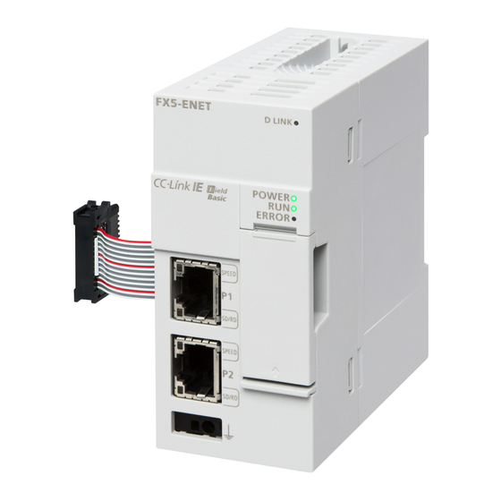
Part Names This chapter describes the names of each part of the FX5-ENET. 2-4.5 mounting holes [10] [11] [12] [13] Name Description External ground terminal Connect an external ground. (Spring clamp terminal block) Link status display LEDs Displays the link status of module. (Page 19 LED display) Extension cable Cable for connecting the module when adding the FX5-ENET. -
Page 21: Led Display
LED display The following table lists the LED display. LED display LED color Description D LINK Green Indicates the operating status of the slave station. • On: Communicating with one or more slave stations • Off: All stations error (Not communicating with any slave station) POWER Green Indicates the power supply status. -
Page 22: Chapter 3 Procedures Before Operation
Checking the specifications of the FX5-ENET Check the specifications of the FX5-ENET. (Page 15 SPECIFICATIONS) Installation of the FX5-ENET Connect the FX5-ENET to the CPU module. For details, refer to the following. MELSEC iQ-F FX5U User's Manual (Hardware) MELSEC iQ-F FX5UC User's Manual (Hardware) Configuring a network Configure a network and set parameters which are required for start-up. - Page 23 MEMO 3 PROCEDURES BEFORE OPERATION...
-
Page 24: Chapter 4 Function List
By using socket communication instructions, any data can be transferred from and to the external devices connected through Ethernet using TCP or UDP. IP address change function The IP address of FX5-ENET can be changed by operating a peripheral device without using GX Works3. Other Functions The following shows an other functions. - Page 25 MEMO 4 FUNCTION LIST 4.3 Other Functions...
-
Page 26: Chapter 5 System Configuration
Configure a network system using modules and partner products supporting CC-Link IE Field Network Basic. Connect the modules in a star topology using a switching hub and Ethernet cables. Line and ring topologies are not possible. (1) FX5-ENET (master station) (2) Hub... -
Page 27: Number Of Link Points
Number of link points The number of link points per slave station is 64 points for RX/RY and 32 points for RWr/RWw. (Page 16 Performance Specifications) However, by changing the number of occupied stations, RX/RY can be set to a maximum of 256 points in increments of 64 points and RWr/RWw can be set to a maximum of 128 points in increments of 32 points. -
Page 28: Chapter 6 Wiring
FG (Ground terminal) The connection destination for the FG terminal of FX5-ENET is a spring clamp terminal block. To connect to the terminal block, there are two ways: by using single wires/strand wires or by using ferrules. Make sure to properly connect in accordance with the following specifications. - Page 29 The wires to connect the spring clamp terminal block are described below. No. of wire per terminal Wire size Single wire, strand wire Ferrule with insulation sleeve One wiring AWG24 to 16 AWG23 to 19 (0.2 to 1.5 mm (0.25 to 0.75 mm ■Wire end treatment Strip the cable about 10 mm from the tip to connect a wire ferrule at the stripped area.
-
Page 30: Wiring Method
Turn the power supply of FX5-ENET (CPU module) and external device off. Push the Ethernet cable connector into the FX5-ENET until it clicks. Pay attention to the orientation of the connector. Lightly pull the connector to check that the connector is securely connected. -
Page 31: Wiring Products
Depending on the connection environment, communication errors may occur due to high-frequency noise from devices other than programmable controllers. The following describes precautionary measures to be taken on the FX5-ENET to avoid the influence of high-frequency noise. [Wiring] • When wiring cables, do not bundle them together with or keep them in close proximity to the main circuit lines or power cables. -
Page 32: Chapter 7 Parameter Settings
[Online] [Write to PLC] The settings are reflected by resetting the CPU module or powering off and on the system. *1 FX5-ENET can be added to GX Works3 also from the module configuration diagram. Writing parameters The FX5-ENET parameters are written to the CPU module. -
Page 33: Basic Setting
Sets the IP address of the FX5-ENET. • Blank Setting Set the class and subnet address of the FX5-ENET to the same settings as • 0.0.0.1 to 223.255.255.254 those of the external devices that communicate with the FX5-ENET. (Default: Blank) Contact the network administrator before setting the IP address. - Page 34 *1 When the parameter is written without the IP address setting (blank), the following address is set. 192.168.3.251 Operational Setting Set the destination alive check conditions for socket communication. Item Description Setting range Timer Settings Change/Set Timer Value Select whether to change timer values from the default. •...
- Page 35 Item Description Setting range RX/RY Setting Points Set the assignment of the number of points for RX/RY in increments of 64 • 64 (1 Occupied Station) points. • 128 (2 Occupied Station) • 192 (3 Occupied Station) • 256 (4 Occupied Station) (Default: 64 (1 Occupied Station)) Start The start number of RX/RY is displayed.
- Page 36 Follow the operating procedure below to use the automatic detection of connected device. Start up a new project in GX Works3 and execute the automatic detection of connected device. Detected slave stations are reflected in the network configuration setting. Change the items such as the connection order and numbers of occupied stations and set station numbers.
- Page 37 Error code Error details and cause Action C061H System error • Check the precautions for the function executed. • Check the operating status and connection status of the target device. • Check the connection of the Ethernet cable and the hub. •...
- Page 38 • Link Scan Setting Set constant scan time, timeout time and number of retries for slave station disconnection detection. Item Description Setting range Constant Scan Time Constant Scan Time Set the constant scan time (ms). 2 to 2000 Setting Setting (2 to 2000) (Default: 2) Slave Station Disconnect Time-out Period (1 to...
- Page 39 • UDP Fixed Buffer Send/Receive Setting Not supported. IP Address The IP address of host station (FX5-ENET) is displayed. Port No. The port no. of host station (FX5-ENET) is displayed. • Blank • 1 to 5548, 5570 to 65534...
-
Page 40: Application Settings
Application Settings Set the following parameters when the functions of the general-purpose Ethernet will be used on FX5-ENET. Security Set the security function. Item Description Setting range IP Filter IP Filter Set whether to enable the IP filter function. • Not Use Settings •... -
Page 41: Chapter 8 Programming
PROGRAMMING This chapter describes program examples of CC-Link IE Field Network Basic. For program examples of general-purpose Ethernet communication, refer to MELSEC iQ-F FX5 User's Manual (Ethernet Communication). Interlock Programs of Cyclic Transmission When creating a cyclic transmission program, configure an interlock such that the processing is performed when normal cyclic transmission between the master station and slave stations is performed. - Page 42 Program example Communication program with station No.1 Communication program with station No.2 8 PROGRAMMING 8.1 Interlock Programs of Cyclic Transmission...
-
Page 43: Program Using Devices
Program using devices A program using devices is provided below. Devices used in the program Device Description U1\G4160.b0 Cyclic transmission status U1\G4100.b0 Cyclic transmission status of each station (station No.1) U1\G4100.b1 Cyclic transmission status of each station (station No.2) Program example Communication program with station No.1 Communication program with station No.2 8 PROGRAMMING... -
Page 44: Chapter 9 Troubleshooting
Is the FX5-ENET mounted correctly? Securely mount the FX5-ENET on the CPU module. If the above actions do not solve the problem, perform the hardware test to check for FX5-ENET failure. (Page 52 Hardware Test) When the ERROR LED turns on or is flashing When the ERROR LED turns on or is flashing, check the following. -
Page 45: Checking The Module Status
Application Error Information Displays the details of the errors currently occurring. Click the [Event History] button to check the history of errors that have occurred on the FX5-ENET, errors detected for each module. Module Information List Displays various status information of the FX5-ENET. - Page 46 Module Information List Switch to the [Module Information List] tab to check various status information of the FX5-ENET. Item Description LED information (Module) Displays the status of the RUN LED and ERROR LED of the FX5-ENET. LED information (Communication) Displays the status of the D LINK of the FX5-ENET.
-
Page 47: Ethernet Diagnostics
To check the status of general-purpose Ethernet, parameter setting and communication status, perform the “Ethernet Diagnostics” of GX Works3. [Diagnostics] [Ethernet Diagnostics] Select the "Module" in the [Target Module Specification]. The following functions can be used in the "Ethernet Diagnostics" window for the FX5-ENET. Function Application Status of Each Connection Displays information concerning status of each connection. - Page 48 Status of Each Connection The status of each connection of the FX5-ENET selected. [Diagnostics] [Ethernet Diagnostics] Select the "Module" in the [Target Module Specification]. Select the [Status of Each Connection] tab. Item Description Connection No./Function Displays the connection number and functions.
- Page 49 Status of Each Protocol The total number of packets sent/received by each protocol of the selected FX5-ENET can be checked. [Diagnostics] [Ethernet Diagnostics] Select the "Module" in the [Target Module Specification]. Select the [Status of Each Protocol] tab.
- Page 50 Connection Status The communication status of the FX5-ENET. [Diagnostics] [Ethernet Diagnostics] Select the "Module" in the [Target Module Specification]. Select the [Connection Status] tab. Item Description Display range Communication Full Duplex/Half Duplex Displays whether the line is full-duplex or half-duplex.
-
Page 51: Checking The Buffer Memory
For the stored error code, refer to Page 57 Module error. Event history function This function collects errors from FX5-ENET, and keeps them in the SD memory card, and data memory or battery backed built-in RAM of the CPU module. -
Page 52: Checking The Network Status
Checking the Network Status The status of the CC-Link IE Field Network Basic network can be confirmed with the CC-Link IE Field Network Basic diagnostics. CC-Link IE Field Network Basic Diagnostics Perform troubleshooting by executing the CC-Link IE Field Network Basic diagnostics of GX Works3 and checking the network status and error details. - Page 53 Item Description Diagnostics Target Group Select a group to be the diagnostics target. Station No. The station number of the slave station is displayed. Occpd Stns The number of occupied stations set in parameter is displayed. Reserved Station The reserved station status set in parameter is displayed. IP Address The IP address set in parameter is displayed.
-
Page 54: Hardware Test
Hardware Test This section describes how to perform a test related to hardware, such as a ROM/RAM of the FX5-ENET. • During the hardware test, values in the buffer memory cannot be referred from the GX Works3 or the program. -
Page 55: Troubleshooting By Symptom
The troubleshooting measures for each symptom during CC-Link IE Field Network Basic are shown below. If an error has occurred in the FX5-ENET, identify the error cause using the GX Works3. (Page 43 Checking the Module Status) When the diagnostics function does not start If the CC-Link IE Field Network Basic diagnostics does not start, check the following. - Page 56 When cyclic data cannot be read/written from/to the slave station correctly If the cyclic data cannot be read in correctly even though the CC-Link IE Field Network Basic diagnostics state is transmitting, check the following. ■CC-Link IE Field Network Basic Check item Action Is the IP address for the master station/slave station set correctly?
- Page 57 ■CC-Link IE Field Network Basic Check item Action Is the timeout time setting of the master station too short? Increase the timeout time of the master station. Are there any slave stations having an error? Perform troubleshooting for the slave station having an error. Is the line load high? Lower the CC-Link IE Field Network Basic communication frequency, and lower the line load.
-
Page 58: List Of Error Codes
This section lists the error codes, error details and causes, and actions for the errors that occur in the processing for data communications between the FX5-ENET and external devices or that are caused by processing requests from the CPU module on the own station. -
Page 59: Module Error
Error codes when a module error occurs are classified into major error, moderate error, and minor error, and can be checked in the [Error Information] tab of the "Module Diagnostics" window of the FX5-ENET. (Page 43 Module diagnostics) The error codes are stored in ‘Latest error code’ (Un\G29). - Page 60 2DA5H Parameter error A parameter error in external device Reexamine and correct the setting of the fixed buffer configuration was detected. transmission in external device configuration in the FX5-ENET module parameters. 2DA6H Parameter error A parameter error in external device Reexamine and correct the setting of the IP address in external configuration was detected.
- Page 61 Error Error name Error details and causes Action code 3082H Parameter error The timer change is outside the specified Please consult your local Mitsubishi representative. range. 3085H Parameter error The destination alive check start interval timer Please consult your local Mitsubishi representative. is outside the range.
-
Page 62: Ethernet Communication Error
Ethernet communication error The Ethernet communication error codes can be checked in “Status of Each Connection” on the "Ethernet Diagnostics" screen of FX5-ENET. (Page 46 Status of Each Connection) The error codes will be stored in ‘Error code’ (Un\G108 to Un\G139). -
Page 63: List Of Event Code
List of Event Code The following table lists events that occur in the FX5-ENET. Event Event Event Event Detected event Detailed information code type category status Detailed Detailed Detailed information 1 information 2 information 3 1080 System Error... - Page 64 Event Event Event Event Detected event Detailed information code type category status Detailed Detailed Detailed information 1 information 2 information 3 3052 System Error Moderate Link-down Failure information 3053 System Error Moderate Timeout Failure information ...
- Page 65 Event Event Event Event Detected event Detailed information code type category status Detailed Detailed Detailed information 1 information 2 information 3 3086 System Error Moderate The start interval timer unit is outside Parameter the specified range (Data information communication timer setting parameter) ...
- Page 66 Event Event Event Event Detected event Detailed information code type category status Detailed Detailed Detailed information 1 information 2 information 3 3E34 System Error Major Fixed memory block acquisition/release Failure parameter error information 3E35 System Error Major The variable memory block acquisition/ ...
-
Page 67: Appendices
APPENDICES Appendix 1 External Dimensions This chapter describes the external dimensions of the FX5-ENET. 2-4.5 Mounting holes (Unit: mm) APPX Appendix 1 External Dimensions... -
Page 68: Appendix 2 Standards
Caution for when the FX5-ENET is used When the FX5-ENET is used, attach a ferrite core and make 3 turns within approximately 200 mm from the power cable connectors. (Ferrite core used in tests by Mitsubishi: ZCAT3035-1330 manufactured by TDK Co.) -
Page 69: Appendix 3 Module Label
Appendix 3 Module Label The buffer memory of the FX5-ENET can be set using module label. Structure of the module label The module label name is defined with the following structure. • "instance name"_"data format""data type"_"label name"_D • "instance name"_"data format""module number""data type"_"label name"_D ■Instance name... -
Page 70: Appendix 4 Buffer Memory
Buffer Memory The buffer memory is used to exchange data between the FX5-ENET and the CPU module or external devices. Buffer memory values are set to their defaults (initial values) when the system is powered off or the CPU module is reset. -
Page 71: Details Of Buffer Memory Addresses
The following describes the buffer memory addresses of the FX5-ENET. Latest error code ■Latest error code (Un\G29) The latest error code that has occurred in FX5-ENET is stored. (0 is stored when communications are normal.) For details on error code, refer to Page 57 Module error. Module information ■Module information (Un\G30) - Page 72 Un\G36 Module error clear request Requests to clear the error that has occurred in FX5-ENET. To request to clear the module error, turn off, on and off the signal. Issuing the request after the cause of the error is removed will clear the followings.
- Page 73 IP address storage area write request ■IP address storage area write request (Un\G56) Specify whether to write the stored values of ‘IP address setting’ (Un\G50 to Un\G51), ‘Subnet mask pattern setting’ (Un\G52 to Un\G53) and ‘Default router IP address setting’ (Un\G54 to Un\G55) to the IP address storage area. •...
- Page 74 IP address storage area clear error code ■IP address storage area clear error code (Un\G62) Stores error codes if clearing of IP address storage area fails. • 0: Normal (no error) • 1921H: ‘IP address storage area write request’ (Un\G56) and ‘IP address storage area clear request’ (Un\G58) were simultaneously turned off and on.
- Page 75 Default gateway IP address ■Default gateway IP address (Un\G76 to Un\G77) Stores default gateway IP address on the own station set with GX Works3. (Page 31 Basic Setting) The stored values can be changed by the IP address change function. Address Description Un\G76...
- Page 76 Initial error code ■Initial error code (Un\G159) The error codes that occur during initialization of FX5-ENET are stored. (0 is stored when communications are normal.) For details on error code, refer to Page 57 Module error. Same IP address state storage area ■Same IP address state storage area (Un\G201)
- Page 77 RX7F0 to RX7FF Remote output (RY) ■Remote output (RY) (Un\G1256 to Un\G1383) Set the output data (bit unit) to be sent from the master station (FX5-ENET) to the slave station with cyclic transmission. Address Remote output Description Un\G1256 •...
- Page 78 RWr1 Un\G3023 RWr3FF Remote register (RWw) ■Remote register (RWw) (Un\G3024 to Un\G4047) Set the output data (word unit) to be sent from the master station (FX5-ENET) to the slave station with cyclic transmission. Address Remote register Description Un\G3024 RWw0...
- Page 79 Data link status of each station ■Data link status of each station (Un\G4104 to Un\G4105) Stores the slave station data link status for each station No. Address Station number Description Un\G4104 1 station • On: Faulty station • Off: Normally operating station 2 station ...
- Page 80 Link scan information (group number 2) ■Link scan information (group number 2) (Un\G4121 to Un\G4123) Link scan information of group number 2 is stored. Address Name Description Un\G4121 Maximum link scan time (Unit: ms) The maximum link scan time value during cyclic transmission is stored. (Unit: ms) Un\G4122 Minimum link scan time (Unit: ms) The minimum link scan time value during cyclic transmission is stored.
- Page 81 Address Name Description Un\G4139 Accumulated number of timeouts After the END instruction of the scan where the bit 0 of 'Diagnostic information display request' (Un\G4162) is turned off and on is executed, the accumulated number of timeouts that occurred in a slave station specified in 'Diagnostic request information' (Un\G4127) is stored.
- Page 82 CCIEF Basic each status ■CCIEF Basic each status (Un\G4160) Each status of CC-Link IE Field Network Basic is stored. Address Name Description Un\G4160 Cyclic transmission status This register turns ON when initial process is completed. Turns OFF when the cyclic transmission is stopped because of an error, etc. •...
-
Page 83: Appendix 5 Processing Time
Appendix 5 Processing Time The processing time of CC-Link IE Field Network Basic consists of the time components below. Sequence scan time + Link scan time + Slave station response processing time = Transmission delay time Master station Slave station Device Link device Link device... -
Page 84: Index
INDEX ......22 Automatic return . . . 22,50 CC-Link IE Field Network Basic diagnostics ....30 Communication mode . - Page 85 MEMO...
-
Page 86: Revisions
First Edition This manual confers no industrial property rights or any rights of any other kind, nor does it confer any patent licenses. Mitsubishi Electric Corporation cannot be held responsible for any problems involving industrial property rights which may occur as a result of using the contents noted in this manual. -
Page 87: Warranty
WARRANTY Please confirm the following product warranty details before using this product. Gratis Warranty Term and Gratis Warranty 2. Onerous repair term after discontinuation of production Range If any faults or defects (hereinafter "Failure") found to Mitsubishi shall accept onerous product repairs for be the responsibility of Mitsubishi occurs during use of seven (7) years after production of the product is the product within the gratis warranty term, the... -
Page 88: Trademarks
TRADEMARKS Microsoft and Windows are either registered trademarks or trademarks of Microsoft Corporation in the United States and/or other countries. Ethernet is a trademark of Xerox Corporation. PROFIBUS is a trademark of PROFIBUS Nutzerorganisation e.V. Anywire and ANYWIREASLINK is a registered trademark of the Anywire Corporation. ... - Page 90 Manual number: SH(NA)-082026ENG-A Model: FX5-U-ENET-E Model code: 09R736 When exported from Japan, this manual does not require application to the Ministry of Economy, Trade and Industry for service transaction permission. HEAD OFFICE: TOKYO BUILDING, 2-7-3 MARUNOUCHI, CHIYODA-KU, TOKYO 100-8310, JAPAN Specifications are subject to change without notice.
Need help?
Do you have a question about the FX5-ENET and is the answer not in the manual?
Questions and answers