Table of Contents
Advertisement
Advertisement
Table of Contents

Related Manuals for ITRON ACE6000


Summary of Contents for ITRON ACE6000
- Page 1 ACE6000 User Guide...
- Page 2 Copyright © 2010 Itron S.A.S. All rights reserved. No part of this publication may be reproduced, transmitted, stored in a retrieval system, or translated into any language in any form by any means without the written permission of Itron S.A.S. All trade marks are acknowledged.
-
Page 3: Table Of Contents
Contents 1. About this guide ......................3 1.1. Audience ..........................3 1.2. Scope ..........................3 2. Abbreviations ......................5 3. Certification ......................... 7 3.1. Applicable standards ......................7 3.2. CE Certificate of conformity ....................8 3.3. End-of-life disposal ......................9 4. - Page 4 ACE6000 User Guide 7.10.4.4. Demand calculation ......................41 7.10.4.5. End of integration (EOI) ....................42 7.10.4.6. Excess demand modes ....................42 7.10.5. Load profiles ........................44 7.10.5.1. Excess energy ........................45 7.10.6. Meter billing ........................45 7.10.6.1. Billing periods ........................45 7.10.6.2.
-
Page 5: About This Guide
1.1. Preliminary notice While Itron strives to make the content of its marketing materials as timely and accurate as possible, Itron makes no claims, promises, or guarantees about the accuracy, completeness, or adequacy of, and expressly disclaims liability for errors and omissions in, such materials. No warranty of any kind, implied, expressed, or statutory, including but not limited to the warranties of non-infringement of third party rights, title, merchantability, and fitness for a particular purpose, is given with respect to the content of these marketing materials. - Page 6 ACE6000 User Guide...
-
Page 7: Abbreviations
Abbreviations Alternating current Mega (10 ANSI American national standards Maximum institute European conformity (logo) Maximum demand indicator Cosem Companion specification for energy Measurement instruments directive (European metering Union) Current transformer Minimum Direct current Millimetres DLMS Device language message Nominal specification Daylight savings time Non-volatile memory End of billing... - Page 8 ACE6000 User Guide...
-
Page 9: Certification
The HF resistance is relative to the frequency domain from 2kHz to 150kHz, the immunity levels are far in excess of the values generated by LV loads. The following outline the approval standards in the regulated frequency ranges which all Itron MID approved meters comply with: EN61000-3-2 –... -
Page 10: Ce Certificate Of Conformity
ACE6000 User Guide EMC Directive 2004/109/EC as amended by 92/31/EEC and 93/68/EEC. Compliance has been demonstrated by compliance with EN62052-11 and EN62053-21. 3.2. CE Certificate of conformity... -
Page 11: End-Of-Life Disposal
3.3. End-of-life disposal ACE6000 meters comply with the requirements of WEEE regulations for recycling or reuse of materials. At the end of their service life, meters should be uninstalled and then passed to a licenced/certified contractor for disposal in accordance with these regulations and with all applicable local regulations. - Page 12 ACE6000 User Guide...
-
Page 13: Safety Information
Safety information Meters must be installed and maintained only by suitably-qualified personnel. Observe the following safety advice when performing installation or service work on meters. Meter handling Before installing or removing a meter, or removing the terminal cover for any reason, isolate the meter from the mains supply by removing the supply-side fuses or using alternative local arrangements. - Page 14 ACE6000 User Guide...
-
Page 15: General Information
General information 5.1. Meter overview The ACE6000 is a static, polyphase, four-quadrant, multi-rate meter. It is intended for large commercial to industrial applications. Depending on the factory configuration, the meter provides the following minimum features and functions: Multi-energy registering Active, Reactive and Apparent energy (import and export) -
Page 16: General Specifications
ACE6000 User Guide Excess energy Power factor aggregate quantity RMS voltage and current per phase quantity Frequency Ambient temperature Alarm status Power factor per phase Incremental data Communication RS232 or RS485 DLMS-Cosem compliant PSTN, LAN (TCP/IP), GSM and GPRS media supported... -
Page 17: Meter Support Tools
5.3. Meter support tools The ACE6000 meters have an extensive range of optional facilities and settings, enabling them to be configured to suit individual requirements. In general, a meter is fully configured and programmed for its intended application prior to despatch from the factory. -
Page 18: Configuration Options
ACE6000 User Guide AIMS Pro AIMS Pro is compliant with the following Microsoft Windows™ operating systems: Windows 98 NT and XP 2000 and 2003 ACE Pilot ACE Pilot is compliant with the following Microsoft Windows™ operating systems: XP (SP2+) 2003 and 2008 Vista and Seven 5.4. - Page 19 Erreur ! Utilisez l'onglet Accueil pour appliquer Heading 1 au texte que vous souhaitez faire apparaître ici. 4 x Control outputs + RS232 4 x Control outputs + RS485 With daisy-chaining capability Voltage connection Code Option Comments 3 x 220/380V to 3 x 240/415V 3 or 4 Wire 3 x 57.7/100V to 3 x 63.5/110V 3 or 4 Wire...
-
Page 20: Meter Markings
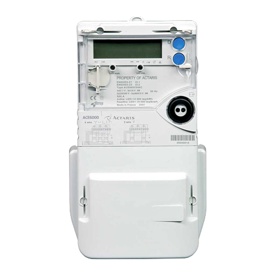
ACE6000 User Guide 5.5. Meter markings The meter cover is laser-marked with at least the information illustrated below, in accordance with IEC 62053-52. Additional markings may be present, and the layout of the markings will vary, according to the meter configuration and specific customer requirements. -
Page 21: Terminal Numbering
Erreur ! Utilisez l'onglet Accueil pour appliquer Heading 1 au texte que vous souhaitez faire apparaître ici. 5.5.1. Terminal numbering Terminal numbers corresponding to the connection diagram are moulded into the meter case, below the terminal block. Auxiliary terminal labels are laser-printed onto the case, adjacent to the terminals. Any terminal numbering will be in accordance with the relevant DIN standard at the time of manufacture unless alternative custom numbering is requested. - Page 22 ACE6000 User Guide...
-
Page 23: Technical Specification
Technical specification General Parameter Description Data Meter Type ACE6000 Connection wiring 3 or 4 wires Connection configuration Direct or Transformer Terminal wiring VDE (asymmetrical) Metrology Four quadrant Active and Reactive (import and export) Metrology sensors Mutual Conductance Transformers Registering modes... - Page 24 ACE6000 User Guide Direct connection starting current and short-time over current Parameter Details Starting current Ib/250 Maximum load capacity (over half- 30Imax cycle) Transformer connection starting current and short-time over current Parameter Details Class 1 Ib/500 Class 0.5 / Class 0.2 Ib/1000 Maximum load capacity 0.5 secs...
- Page 25 Erreur ! Utilisez l'onglet Accueil pour appliquer Heading 1 au texte que vous souhaitez faire apparaître ici. Parameter Description Data GPRS in tunnelling mode With external modem With external modem Real-time operation i.a.w. IEC62056-21 Modem power supply approx 10V, 100mA, 0.9W max on RJ45 connectors Output Parameter...
- Page 26 ACE6000 User Guide Parameter Description Data 1.2/50μsecs auxiliary circuits Source impedance 42 ohms Electrostatic discharge Electrostatic discharge according to IEC61000-4-2 Contact discharge 8kV, 10 cycles Air discharge 15kV, 10 cycles Immunity to RF fields RF fields i.a.w. IEC61000-4-3 With current...
-
Page 27: Technical Description
Technical description The main components of the ACE6000 meter are assembled onto two printed circuit boards (PCBs): the PSU board contains all the metrology voltage divider circuitry and the switched-mode power supply the top I/O board contains all the other meter circuitry including the I/O and communication ports,... -
Page 28: Measurement Error Correction
ACE6000 User Guide High frequency resistance A low-pass filter with a cutting frequency at 2kHz is introduced on the I and V measurement channels. These filters make the metrology resistant against High Frequency (HF) currents superimposed on 50Hz nominal currents and added harmonic currents and also resistant against HF voltage superimposed on 50Hz nominal voltages and added harmonic voltages. -
Page 29: Power Supplies
7.4. Power-fail operation In the event of a continuous absence of power, all ACE6000 meter data is saved in a non-volatile memory, with a retention time of at least 10 years without the aid of any backup power. The contents of the non-volatile memory are regularly checked with checksum markers and a fatal alarm (page 56) is raised if data corruption is detected. -
Page 30: Calendar
ACE6000 User Guide 7.6. Calendar The calendar provides a flexible and configurable switching regime that handles up to sixteen energy rate switches per day. The calendar also has the ability to apply different energy rate regimes during different seasons of the year and on designated individual days. -
Page 31: Seasons
Erreur ! Utilisez l'onglet Accueil pour appliquer Heading 1 au texte que vous souhaitez faire apparaître ici. 7.7.2. Seasons The meter supports up to twelve seasons per year, for which different tariff regimes can be programmed. These seasons are defined by start dates, which can be set individually or derived from programmed daylight saving dates/times. -
Page 32: Indexes
ACE6000 User Guide 7.7.5. Indexes The contractually specified tariffs define the energy and demand rates being used by the meter. However, in many cases, active energy has more rates defined (for billing purposes) than reactive energy. An index describes a combination of energy and demand rates that are activated simultaneously. - Page 33 Erreur ! Utilisez l'onglet Accueil pour appliquer Heading 1 au texte que vous souhaitez faire apparaître ici. During a power failure, the super-capacitor is the first backup device to be drained. An icon on the LCD is lit when the battery voltage falls below a preset threshold value (nominal battery voltage value 3V).
-
Page 34: Reading Without Power (Rwp)
ACE6000 User Guide 7.9. Reading without power (RWP) The meter can be factory-fitted with an option that allows meter reading even when main network power is missing. The power for this Reading Without Power (RWP) feature is provided by two dedicated (½ AA type) batteries fitted in a holder located under the meter terminal cover, as shown: The expected battery life is 10 years based on a typical usage cycle of 5 x 5minute readings a year. -
Page 35: Metered Quantities
Erreur ! Utilisez l'onglet Accueil pour appliquer Heading 1 au texte que vous souhaitez faire apparaître ici. 7.10. Metered quantities 7.10.1. Four quadrant metering The meter measures various energy values or quantities, in all four quadrants of the AC waveform. 7.10.1.1. - Page 36 ACE6000 User Guide Per quadrant Aggregate kvarh Q1 ph 1 kvarh Q1 agg kvarh Q2 ph 1 kvarh Q2 agg kvarh Q3 ph 1 kvarh Q3 agg kvarh Q4 ph 1 kvarh Q4 agg kvarh Q1 ph 2 kvarh Q2 ph 2...
-
Page 37: Summation Energy
Erreur ! Utilisez l'onglet Accueil pour appliquer Heading 1 au texte que vous souhaitez faire apparaître ici. 7.10.1.2. Summation energy The meter can be configured with up to four summation energy registers that algebraically sum the contents of up to five energy rate registers recording the same type of energy. Summation - 4 Quantities Quantity Summation energy quantities can be measured in:... -
Page 38: Total Energy Registers (Ter)
ACE6000 User Guide 7.10.2. Total energy registers (TER) Total energy registers (TER) are: dedicated to storing the total accumulation of an energy quantity independent of any tariff switching or calendar definition not reset at the end of a billing period... -
Page 39: Energy Rate Registers
Erreur ! Utilisez l'onglet Accueil pour appliquer Heading 1 au texte que vous souhaitez faire apparaître ici. 7.10.3.2. Energy rate registers The meter records the consumption of all tariff-based metered energy in up to thirty-two individual energy rate registers. Each of the meter energy channels (page 36) can have a maximum allocation of eight energy rate registers from within this limit. -
Page 40: Summation Registers
ACE6000 User Guide 7.10.3.3. Summation registers The meter can be configured with up to four summation energy registers that algebraically sum the contents of up to five energy rate registers recording the same type of energy. The illustration below shows two (out of four) summation paths with five inputs (A,B,C,D and E) each. -
Page 41: Demand Channels
Erreur ! Utilisez l'onglet Accueil pour appliquer Heading 1 au texte que vous souhaitez faire apparaître ici. 7.10.4.1. Demand channels For demand registering purposes the meter can be configured with up to ten independent demand channels, each channel being selected from the list of available measured energy quantities. In addition, the calculated aggregate power factor can be allocated to a demand channel. - Page 42 ACE6000 User Guide...
-
Page 43: Demand Calculation
Erreur ! Utilisez l'onglet Accueil pour appliquer Heading 1 au texte que vous souhaitez faire apparaître ici. Sliding mode In the sliding mode the demand period is divided into between 1 and 15 fixed integration periods. The total maximum duration of a sliding demand period is 15 (maximum periods) x 60 (maximum minutes) = 900 minutes. The illustration below shows a sliding mode demand period comprising 4 integration periods with, for example a duration of T = 5 minutes. -
Page 44: End Of Integration (Eoi)
ACE6000 User Guide 7.10.4.5. End of integration (EOI) The meter can be configured so that up to five different sources can trigger an end of integration period (EOI): the meter real-time clock a time change an active signal on a control input... - Page 45 Erreur ! Utilisez l'onglet Accueil pour appliquer Heading 1 au texte que vous souhaitez faire apparaître ici. End of integration If the threshold value is exceeded during the integration period, the meter indicates an excess at the end of the integration period and during subsequent integration periods. At the end of each integration period the excess demand indicators are reset only if the rising value has remained lower than the excess threshold.
-
Page 46: Load Profiles
ACE6000 User Guide 7.10.5. Load profiles Load profiles are of interest to both the utility and the end customer as they can help determine which electricity contract and tariff rates may be the most appropriate. As well as analysis, load profile data can be used for billing purposes. -
Page 47: Excess Energy
Erreur ! Utilisez l'onglet Accueil pour appliquer Heading 1 au texte que vous souhaitez faire apparaître ici. 7.10.5.1. Excess energy Up to three channels in each load profile array can be configured as excess energy channels. These are triggered to record energy quantities once the specified quantity has exceeded a configurable threshold. These channels can also be configured as simple load profile channels. -
Page 48: Historical Buffer Registers
ACE6000 User Guide Lock-out time End of billing (EOB) source triggers can also disable other EOB sources from having any effect for the duration of a pre-configured lock-out time. This prevents any further spurious or unnecessary EOB events from occurring. - Page 49 Erreur ! Utilisez l'onglet Accueil pour appliquer Heading 1 au texte que vous souhaitez faire apparaître ici. EOB summary registers These historical buffer registers record a specific set of values associated with end of billing (EOB) events, as follows: number of EOB actions (cumulative) EOB date and time EOB source trigger: communication...
-
Page 50: Network Quality Monitoring
ACE6000 User Guide 7.11. Network quality monitoring As a manufacturing option, 4 wire system meters can be configured to monitor various distribution-network voltage-quality parameters. However, this facility is only available if specifically requested at the time of manufacture and it is not available on 3 wire system meters. - Page 51 Erreur ! Utilisez l'onglet Accueil pour appliquer Heading 1 au texte que vous souhaitez faire apparaître ici. Voltage sags A voltage sag is detected if the distribution-network input voltage drops below the sag start threshold value and continues until the voltage rises above the sag end threshold value. However, if the input voltage drops below the sag start threshold and then subsequently drops below the cut start threshold, the sag defect is ignored as a cut start always erases a sag start.
-
Page 52: Monitoring
ACE6000 User Guide 7.12. Monitoring The meter monitors and records events in the following categories: Network Anti-tamper or fraud Meter status Billing Note: Some of the monitored events could exist in more than one category. Monitored events Event name Network... - Page 53 Erreur ! Utilisez l'onglet Accueil pour appliquer Heading 1 au texte que vous souhaitez faire apparaître ici. Frequency The meter calculates the instantaneous frequency of the distribution-network voltage waveform using a zero crossing technique that ensures an accurate result even if one or two incoming phases are lost. The maximum and minimum frequency values within a billing period (page 45) are recorded by the meter.
- Page 54 ACE6000 User Guide Cover opening The meter detects cover opening events and records the following parameters: number of cover openings (incremental) the last 10 cover openings (with time stamp and duration) The meter detects and records the first cover opening event during a power failure.
-
Page 55: Fraud Protection Measures
7.13. Fraud protection measures The meter incorporates the following features designed to prevent tampering and/or assist in the detection of attempted fraud: Feature Description Anti-fraud measuring mode The meter may be configured to register energy with an anti-fraud algorithm. Meter and terminal seals The meter body and terminal cover may be independently sealed with conventional wire or plastic seals. -
Page 56: Magnetic Field Detection
ACE6000 User Guide 7.13.1. Magnetic field detection The meter can be optionally factory-equipped with a sensor that detects external magnetic fields. This type of field is typically applied to the meter in an attempt (a magnetic attack) to defraud the utility company by disturbing the measurement metrology sensors. -
Page 57: Alarm And Event Management
Erreur ! Utilisez l'onglet Accueil pour appliquer Heading 1 au texte que vous souhaitez faire apparaître ici. 7.14. Alarm and event management 7.14.1. Logbook The meter is factory programmed with a list of pre-defined metering Events. Using the meter support tool, events from the list can be selected so that if they occur, a time-stamped record is made in the meter Logbook. -
Page 58: Alarm Type And Classification
ACE6000 User Guide 7.14.3. Alarm type and classification Alarm types In addition to logbook events, the meter manages two types of alarm: Fatal These alarms cause the meter to enter the non-operational mode (STOP displayed on the LCD) where only instantaneous values are processed and no further registration of energy or demand/load profile calculation is performed. -
Page 59: Communications
GSM - Global System for Mobile communication GPRS - General Packet Radio Service For all media types Itron recommends the installation of the Sparklet™ modem. However, many third-party manufactured modems are supported. A support tool for the Sparklet modem is available to configure all aspects of operation across all media types. -
Page 60: Real-Time Data
ACE6000 User Guide Modem power supply Where fitted, the RJ45 connector is located under the terminal cover and can provide a DC supply voltage (VMDM) suitable for powering an external modem. RS232 Function RS485 Function VMDM VMDM Approx +10V DC at 100mA (0.9W max) Approx +10V DC at 100mA (0.9W max) -
Page 61: Communication Protocols And Networking
In this mode the modem receives data from the meter in HDLC protocol (via the serial port) and manages the communication operation. ACE6000 Compatibility information All existing Mark 1 and Mark 2 version meters are compatible with the following communication modes when using a suitable RS232 or RS485 Sparklet modem. -
Page 62: Communication Management
ACE6000 User Guide 8.6. Communication management In accordance with IEC 62056-53, security access levels of the DLMS/COSEM protocol are applied to meter communication and interfacing. Confidentiality and privacy of data are managed by COSEM logical devices in the meter (which can be addressed individually) and different COSEM client identifications (connection profiles). -
Page 63: Meter Displays
Meter displays The meter is equipped with a front-panel mounted, high-visibility, liquid crystal display (LCD) capable of showing the values held in all billing and other registers, as well as configuration and other information displays. The meter configuration defines which displays are available to the user, the resolution of those displays and the order in which parameters appear. - Page 64 ACE6000 User Guide The following range of energy units can be displayed: varh kvar kvarh kVAh Mvar Mvarh MVAh The annunciator indicators represent the following: Icon Name Description Alternate This icon is permanently lit when the alternate long list display mode is active and flashes when the alternate short list display mode is active.
-
Page 65: Meter Pushbuttons
Erreur ! Utilisez l'onglet Accueil pour appliquer Heading 1 au texte que vous souhaitez faire apparaître ici. Displayed alarms Typically, the following alarm conditions will be indicated by S12 on the LCD (these may change due to meter firmware revision): internal or external ram error internal or external program memory error external clock, configuration or programming incoherence... -
Page 66: Meter Display Modes
ACE6000 User Guide 9.3. Meter display modes The meter can be configured with up to three, individual parameter display lists. Each display list can contain up to a maximum of 100 parameters, such as: the current energy and demand registers values... - Page 67 Erreur ! Utilisez l'onglet Accueil pour appliquer Heading 1 au texte que vous souhaitez faire apparaître ici. On entering either alternate display mode, the LCD is backlit and shows the first parameter in the display sequence. Alternate long mode This mode provides a manual display of pre-selected parameters accessible to the end user. The ALT annunciator icon will be lit.
- Page 68 ACE6000 User Guide P.01 P.02 and MID (page 82) On entering this display mode, the LCD is backlit and shows the first level in the display sequence. These levels will only be displayed if the meter has been configured accordingly.
-
Page 69: Installation
Following installation, ensure that the meter covers are correctly fitted and sealed to prevent user access. 10.2. Environmental ACE6000 meters are certified for indoor use only. Do not install meters outdoors unless they are housed in an enclosure which can maintain the specified environmental requirements. Parameter Range Temperature -40°C to +70°C... -
Page 70: Dimensions
ACE6000 User Guide 10.3. Dimensions The meter can be factory-fitted with either a short or long terminal cover. Meter dimensions - short terminal cover Item Dimension Description Meter body width Terminal cover width Meter length including terminal cover Overall length, hanging bracket fully retracted... -
Page 71: Fixings
Erreur ! Utilisez l'onglet Accueil pour appliquer Heading 1 au texte que vous souhaitez faire apparaître ici. Terminal cover depth All dimensions are in millimetres. 10.4. Fixings The meter is fitted with a four-step adjustable hanging bracket that provides an upper fixing point. Two further lower fixing points are located within the terminal area;... -
Page 72: Using Aluminium Cables
ACE6000 User Guide Upper fixing point to lower fixing points (centre to centre) Hanging bracket in first position (fully retracted) Second position Third position Forth position (fully extended) Left to right lower fixing points (centre to centre) Lower fixing point centre to lower edge of short terminal cover Lower fixing point centre to lower edge of long terminal cover All dimensions are in millimetres. -
Page 73: Cabling
Erreur ! Utilisez l'onglet Accueil pour appliquer Heading 1 au texte que vous souhaitez faire apparaître ici. 10.6. Cabling Main terminal wiring The main terminal is the same design and specification for both Direct and Transformer connection meter types. Terminal Function Terminal Function... - Page 74 ACE6000 User Guide 4 wire asymmetrical (VDE) current transformer configuration Terminal Phase Function Terminal Phase Function I1 - CT1 in I3- CT3 in U1 - Voltage U3 - Voltage I1 - CT1 out I3 - CT3 out I2 - CT2 in...
- Page 75 Erreur ! Utilisez l'onglet Accueil pour appliquer Heading 1 au texte que vous souhaitez faire apparaître ici. 3 wire asymmetrical (VDE) current transformer configuration Terminal Phase Function Terminal Phase Function I1 - CT in I3- CT in U1 - Voltage U3 - Voltage I1 - CT out I3 - CT out...
- Page 76 ACE6000 User Guide 4 wire asymmetrical (VDE) direct connection configuration Terminal Phase Function Terminal Phase Function I1 - Phase 1 in I3- Phase 3 in No connection No connection I1 - Phase 1 out I3 - Phase 3 out I2 - Phase 2 in...
- Page 77 Erreur ! Utilisez l'onglet Accueil pour appliquer Heading 1 au texte que vous souhaitez faire apparaître ici. Terminal Phase Function Terminal Phase Function I1 - Phase 1 in I3 - Phase 3 in No connection No connection I1 - Phase 1 out I3 - Phase 3 out I2 - Phase 2 in 10/11...
-
Page 78: Battery
ACE6000 User Guide 10.7. Battery The meter is designed so the lithium battery can be safely installed or replaced while the meter is operating, as follows: 1. Unseal and open the hinged front cover. 2. If fitted, remove the seal from the battery holder. -
Page 79: Sealing The Meter
Erreur ! Utilisez l'onglet Accueil pour appliquer Heading 1 au texte que vous souhaitez faire apparaître ici. read the Total Energy Registers (TER) values read all instantaneous values read the meter status values and its configuration erase any non-fatal alarms 7. - Page 80 ACE6000 User Guide...
-
Page 81: Technical Appendix
Technical appendix 11.1. Logbook contents The following table contains a list of selectable logbook events (these may change due to meter firmware revision): Event Description PERIODICAL EOI Periodical end of integration period ASYNCHRONOUS EOI Asynchronous end of integration period PERIODICAL EOB Periodical end of billing period PROGRAMMED EOB Pre-programmed end of billing period... -
Page 82: Alarm Descriptions
ACE6000 User Guide RESET_MEASUREMENT_DATA Reset of measurement data START_MEASUREMENT Start measurement STOP_MEASUREMENT Stop measurement START_TRIGGERED_TESTS Start triggered tests STOP_TRIGGERED_TESTS Stop triggered tests END_OF_DATA_SAVING End of current data saving LOAD_PROFILE_RESET Load profile reset PASSWORD RESTORATION Password restoration INDEX_CLOCK_LOSS Default clock loss index... - Page 83 Erreur ! Utilisez l'onglet Accueil pour appliquer Heading 1 au texte que vous souhaitez faire apparaître ici. CURRENT REVERSAL (PHASE 1) Self-healing Change of direction of current flow on phase 1 CURRENT REVERSAL (PHASE 2) Self-healing Change of direction of current flow on phase 2 CURRENT REVERSAL (PHASE 3) Self-healing Change of direction of current flow on phase 3...
-
Page 84: Mid Display List
ACE6000 User Guide CONFIGURATION Some possible causes for this alarm may be: INCOHERENCE An energy rate is used but quantity is not selected. Day is not defined from the weekly profile calendar. Incorrect scaler is selected from load profile channel. - Page 85 Erreur ! Utilisez l'onglet Accueil pour appliquer Heading 1 au texte que vous souhaitez faire apparaître ici. rS 485 or tcP IP Voltage range VoltAGE 57 7-100 or 127-220 or 230-400 Control output number CO Numb 0 or 4 Nominal frequency 50.00 or 60.00 Value of CT numerator CTn 1...
Need help?
Do you have a question about the ACE6000 and is the answer not in the manual?
Questions and answers