Table of Contents
Advertisement
Advertisement
Table of Contents

Related Manuals for ITRON SL7000 IEC7


Summary of Contents for ITRON SL7000 IEC7
- Page 1 SL7000 IEC7 User Guide...
- Page 2 Itron S.A.S. All trade marks are acknowledged. While Itron strives to make the content of its marketing materials as timely and accurate as possible, Itron makes no claims, promises, or guarantees about the accuracy, completeness, or adequacy of, and expressly disclaims liability for errors and omissions in, such materials.
-
Page 3: Table Of Contents
Contents 1. About this guide ......................3 1.1. Audience ..........................3 1.2. Scope ..........................3 1.3. Abbreviations ........................5 2. Certification ......................... 7 2.1. Applicable standards ......................7 2.2. CE Certificate of conformity ....................8 2.3. End-of-life disposal ......................9 3. - Page 4 User Guide SL7000 IEC7 6.9.4.5. End of integration (EOI) ....................44 6.9.4.6. Excess demand modes ....................44 6.9.5. Load profiles ........................46 6.9.5.1. Excess energy ........................47 6.9.6. Meter billing ........................47 6.9.6.1. Billing periods ........................47 6.9.6.2. End of billing (EOB) event ....................47 6.9.6.3.
-
Page 5: About This Guide
About this guide 1.1. Audience This guide is intended for use primarily by meter installers, utility testers and specifying engineers. 1.2. Scope This guide provides all information required to: • understand the principles of operation of the meter • assess the suitability of the meter for any particular application •... -
Page 7: Abbreviations
1.3. Abbreviations Alternating current Mega (10 ANSI American national standards Maximum institute European conformity (logo) Maximum demand indicator Cosem Companion specification for energy Measurement instruments directive (European metering Union) Current transformer Minimum Direct current Millimetres DLMS Device language message Nominal specification Daylight savings time Non-volatile memory... -
Page 9: Certification
Certification 2.1. Applicable standards The SL7000 meters comply, where applicable, with the following standards and regulations. • IEC 62052-11 Electricity metering equipment (AC) - General requirements, tests and test conditions, part 11: Metering equipment (equivalent to EN 6205-11) • IEC 62053-21 Electricity metering equipment (AC) - Particular requirements, part 21: Static meters for active energy (classes 1 and 2), (equivalent to EN 62053-21) •... -
Page 10: Ce Certificate Of Conformity
User Guide SL7000 IEC7 2.2. CE Certificate of conformity... -
Page 11: End-Of-Life Disposal
SL7000 User Guide 2.3. End-of-life disposal SL7000 meters comply with the requirements of WEEE regulations for recycling or reuse of materials. At the end of their service life, meters should be uninstalled and then passed to a licenced/certified contractor for disposal in accordance with these regulations and with all applicable local regulations. -
Page 13: Safety Information
Safety information Meters must be installed and maintained only by suitably-qualified personnel. Observe the following safety advice when performing installation or service work on meters. Meter handling Before installing or removing a meter, or removing the terminal cover for any reason, isolate the meter from the mains supply by removing the supply-side fuses or using alternative local arrangements. -
Page 15: General Information
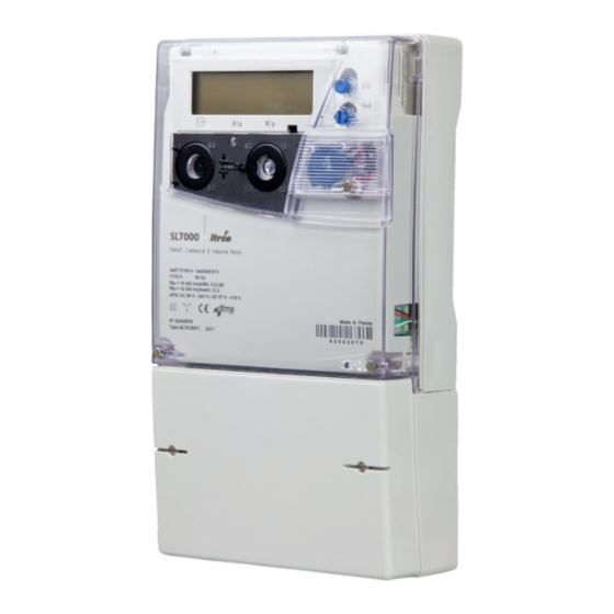
General information 4.1. Meter overview The SL7000 is a static, polyphase, four-quadrant, multi-rate meter. It is intended for large industrial to substation applications. Depending on the factory configuration, the meter provides the following minimum features and functions: Multi-energy registering Active, Reactive and Apparent energy (import and export) Units - Watt (W), Kilowatt (kW) and Megawatt (MW) Maximum 32 individual energy rate registers for 10 energy channels (incremental or cumulative) -
Page 16: General Specifications
User Guide SL7000 IEC7 The diagram below shows the main functional elements of the meter: Liquid crystal display (LCD) Infrared communication port Auxiliary I/O terminal blocks Main wiring terminal block (Transformer connection type shown) Reactive power metrology LED (Rlq) Active power metrology LED (Rlp) -
Page 17: Meter Support Tools
SL7000 User Guide Direct connection specifications Voltage 3 x 57.7/100V up to 3 x 277/480V auto ranging Current Nominal (Ib) Ib 5A Maximum (Imax) Imax : 120A at 50Hz 100A at 60Hz Accuracy Active energy Class 1 Reactive energy Class 1 or 2 Transformer connection specifications Voltage 3 x 57.7/100V up to 3 x 277/480V auto ranging... -
Page 18: Configuration Options
User Guide SL7000 IEC7 4.4. Configuration options 4.4.1. Meter identification Meter options are specified by a multi-character product code, in which each option is designated by one or more characters. The meter cover is laser-marked with this legally required identification code. - Page 19 SL7000 User Guide I/O and COM configuration Code Option I/O Level 2 x RS232 Full 1 x RS232 + 1 x RS485 Full 2 x RS485 Full 2 x RS232 1 x RS232 +1 x RS485 2 x RS485 2 x RS232 Light 1 x RS232 + 1 x RS485 Light...
-
Page 20: Meter Markings
User Guide SL7000 IEC7 4.5. Meter markings The meter cover is laser-marked with at least the information illustrated below, in accordance with IEC 62053-52. Additional markings may be present, and the layout of the markings will vary, according to the meter configuration and specific customer requirements. -
Page 21: Terminal Numbering
SL7000 User Guide 4.5.1. Terminal numbering A connection diagram is displayed on the inside surface of the terminal cover showing typical main supply connections for the meter configuration and type. Terminal numbers corresponding to the connection diagram are moulded into the meter case, either above or below the terminal block depending on the meter connection type. -
Page 23: Technical Specification
Technical specification General Parameter Description Data Meter Type SL7000 Connection wiring 3 or 4 wires Connection configuration Direct or Transformer Terminal wiring VDE (asymmetrical) and for CT only : USE (symmetrical) Metrology Four quadrant Active and Reactive (import and export) Metrology sensors Mutual Conductance Transformers Registering modes... - Page 24 User Guide SL7000 IEC7 Direct connection starting current and short-time over current Parameter Details Starting current Ib/250 Maximum load capacity (over half- 30Imax cycle) Transformer connection starting current and short-time over current Parameter Details Class 1 Ib/500 Class 0.5 / Class 0.2 Ib/1000 Maximum load capacity 0.5 secs...
- Page 25 SL7000 User Guide Parameter Description Data Real-time operation “Real Time Port” i.a.w. IEC62056-21 Modem power supply 10V -10/+20%, 300mA, 3W max on RJ45 connectors. 3W is the maximum shared on the 2 ports for a triphased power supply >100V (Ph/N) Input and output Parameter Description...
- Page 26 User Guide SL7000 IEC7 Parameter Description Data coil) Magnetic DC field according to IEC Fully immune 62053-21 (electromagnet with 1000AT) Magnetic DC field according to Fully immune VDEW (perm magnet) field strength 200mT Surge immunity According to IEC61000-4-5 main circuits...
-
Page 27: Technical Description
Technical description The main components of the SL7000 meter are assembled onto three printed circuit boards (PCBs): • metrology voltage divider circuitry and the switched-mode power supply • microcontroller and memory devices and I/O circuitry • LCD display The block diagram below shows the main functional elements of the meter. -
Page 28: Metrology
User Guide SL7000 IEC7 6.1. Metrology The meter current sensors are integral Mutual Conductance Transformers, which provide a wide dynamic range and guarantee high stability over the operating temperature range of the meter. The three current sensors generate a signal per phase that is proportional to the instantaneous current, while voltage signals are derived by dividing the distribution-network line voltages through a resistive divider. - Page 29 SL7000 User Guide Control input terminals The control input terminal block provides a common connection point and accepts cables up to 2.5mm². Minimum input voltage = 40V (AC/DC) Maximum input voltage = 288V AC, 300V DC Maximum input current = 3mA Terminal Function Typical wiring...
- Page 30 User Guide SL7000 IEC7 Pulse input The meter can be factory-configured with a number of optically-isolated pulse inputs for connection to further DIN S0 meters or other pulse output devices that are compliant with IEC 62053-31. Received pulses are recorded in separate external-energy registers as total pulse counts and can represent metered energy types such as electricity, water or gas as either import or export energy values.
-
Page 31: Power Supplies
SL7000 User Guide Note: Depending on the factory configuration, the meter may not be fitted with pulse outputs 3 to 6. Metrology LED indicators Visible metrology pulses proportional to active and reactive energy consumption are provided via two red LED indicators. -
Page 32: Power-Fail Operation
User Guide SL7000 IEC7 Alternatively, the APS also accepts an external DC voltage ranging from 48V to 145V. Typical DC voltage APS terminal wiring illustrated below: Note: There is no polarization for DC APS (we can connect +Ve on terminal 14 and –Ve on terminal 15. -
Page 33: Energy Rate Switching
SL7000 User Guide 6.7. Energy rate switching The contract between the customer and the utility will usually specify how many energy rates are available and at what times of the day these rates can be applied. These energy rate regimes are known as tariffs. Tariffs are defined and downloaded to the meter using the meter support tool. -
Page 34: Week Profiles
User Guide SL7000 IEC7 6.7.3. Week profiles A week profile is always associated with a season and contains a collection of seven individually-defined day profiles (Monday through to Sunday). The following example illustrates individual weekly profiles for five seasons: Season 6.7.4. -
Page 35: Indexes
SL7000 User Guide The following example illustrates five daily profiles with seven switching-times: Profile 00:00 [3] 06:00 [2] 09:00 [1] 11:00 [2] 18:00 [1] 20:00 [2] 20:00 [3] 00:00 [3] 06:00 [2] 22:00 [3] 00:00 [5] 06:00 [4] 22:00 [5] 00:00 [3] 00:00 [5] Note: The numbers in enclosed brackets, e.g. -
Page 36: Special Days
User Guide SL7000 IEC7 6.7.6. Special days The special days facility is intended to allow energy consumption charges on any locally-significant days, such as religious or public holidays, to be different from the rest of the week in which they occur. -
Page 37: Metered Quantities
SL7000 User Guide 6.9. Metered quantities 6.9.1. Four quadrant metering The meter measures various energy values or quantities, in all four quadrants of the AC waveform. 6.9.1.1. Measured energy quantities The following measured energy quantities are updated every second and recorded in a series of total energy registers (TER): Active Energy - 8 Quantities Per phase... - Page 38 User Guide SL7000 IEC7 Per quadrant Aggregate kvarh Q1 ph 1 kvarh Q1 agg kvarh Q2 ph 1 kvarh Q2 agg kvarh Q3 ph 1 kvarh Q3 agg kvarh Q4 ph 1 kvarh Q4 agg kvarh Q1 ph 2 kvarh Q2 ph 2...
-
Page 39: Summation Energy
SL7000 User Guide External Energy - 8 Quantities Quantity Direction External 1+ Import External 1- Export External 2+ Import External 2- Export External 3+ Import External 3- Export External 4+ Import External 4- Export The meter can register up to four external energy inputs from other electricity, water or gas meters, quantities can be measured in: •... - Page 40 User Guide SL7000 IEC7 RMS - 6 Quantities Voltage Current Urms ph 1 Irms ph 1 Urms ph 2 Irms ph 2 Urms ph 3 Irms ph 3 Power Factor - 4 Quantities Quantity PF ph 1 PF ph 2...
-
Page 41: Total Energy Registers (Ter)
SL7000 User Guide 6.9.2. Total energy registers (TER) Total energy registers (TER) are: • dedicated to storing the total accumulation of an energy quantity • independent of any tariff switching or calendar definition • not reset at the end of a billing period •... -
Page 42: Energy Rate Registers
User Guide SL7000 IEC7 6.9.3.2. Energy rate registers The meter records the consumption of all tariff-based metered energy in up to thirty-two individual energy rate registers. Each of the meter energy channels (page 39) can have a maximum allocation of eight energy rate registers from within this limit. -
Page 43: Summation Registers
SL7000 User Guide 6.9.3.3. Summation registers The meter can be configured with up to four summation energy registers that algebraically sum the contents of up to five energy rate registers (internal or external) recording the same type of energy. The illustration below shows two (out of four) summation paths with five inputs (A,B,C,D and E) each. The result of the summation process is only stored in the register if it is a positive value. -
Page 44: Demand Channels
User Guide SL7000 IEC7 6.9.4.1. Demand channels For demand registering purposes the meter can be configured with up to ten independent demand channels, each channel being selected from the list of available measured energy quantities. In addition, the calculated aggregate power factor can be allocated to a demand channel. -
Page 45: Demand Calculation
SL7000 User Guide Sliding mode In the sliding mode the demand period is divided into between 1 and 15 fixed integration periods. The total maximum duration of a sliding demand period is 15 (maximum periods) x 60 (maximum minutes) = 900 minutes. The illustration below shows a sliding mode demand period comprising 4 integration periods with, for example a duration of T = 5 minutes. -
Page 46: End Of Integration (Eoi)
User Guide SL7000 IEC7 6.9.4.5. End of integration (EOI) The meter can be configured so that up to five different sources can trigger an end of integration period (EOI): • the meter real-time clock • a time change • an active signal on a control input •... - Page 47 SL7000 User Guide • End of integration If the threshold value is exceeded during the integration period, the meter indicates an excess at the end of the integration period and during subsequent integration periods. At the end of each integration period the excess demand indicators are reset only if the rising value has remained lower than the excess threshold.
-
Page 48: Load Profiles
User Guide SL7000 IEC7 6.9.5. Load profiles Load profiles are of interest to both the utility and the end customer as they can help determine which electricity contract and tariff rates may be the most appropriate. As well as analysis, load profile data can be used for billing purposes. -
Page 49: Excess Energy
SL7000 User Guide 6.9.5.1. Excess energy Up to three channels in each load profile array can be configured as excess energy channels. These are triggered to record energy quantities once the specified quantity has exceeded a configurable threshold. These channels can also be configured as simple load profile channels. 6.9.6. -
Page 50: Historical Buffer Registers
User Guide SL7000 IEC7 Lock-out time End of billing (EOB) source triggers can also disable other EOB sources from having any effect for the duration of a pre-configured lock-out time. This prevents any further spurious or unnecessary EOB events from occurring. -
Page 51: Network Quality Monitoring
SL7000 User Guide EOB summary registers These historical buffer registers record a specific set of values associated with end of billing (EOB) events, as follows: • number of EOB actions (cumulative) • EOB date and time • EOB source trigger: •... - Page 52 User Guide SL7000 IEC7 Voltage cuts A voltage cut is detected if the distribution-network input voltage drops below the cut start threshold value and continues until the voltage rises above the cut end threshold value. If the meter is configured for default values, the threshold percentages are: •...
-
Page 53: Monitoring
SL7000 User Guide A typical voltage swell defect event is illustrated below: Unom RMS Input voltage Swell start threshold Swell duration Swell magnitude Swell end threshold 6.11. Monitoring The meter monitors and records events in the following categories: • Network •... - Page 54 User Guide SL7000 IEC7 Auxiliary Power Supply (APS) Alarm is managed only if the APS parameter indicates that an auxiliary power supply is connected. Appearance: The non fatal alarm will be generated when the APS voltage decreases strictly under the lower...
- Page 55 SL7000 User Guide Total harmonic distortion (THD) The meter can be configured to calculate the per phase Total Harmonic Distortion (THD) value for both: • Voltage (Uhrms) • Current (Ihrms) THD is calculated over the full harmonic range from H2 to H13 for 50Hz networks and from H2 to H11 for 60Hz networks.
- Page 56 User Guide SL7000 IEC7 Neutral current Neutral current will typically occur as a result of asymmetrical loads. The meter calculates a neutral current value once every second using a standard homopolar current technique (rms value of the vector sum of the phase currents). When this calculated value exceeds a pre-programmed threshold an alarm can be triggered.
- Page 57 SL7000 User Guide Configurations history The meter records the following configuration event parameters: • number of objects configured (incremental) • last configuration date Watchdog activity The meter detects watchdog events and records the following parameters: • number of watchdog events (incremental) •...
-
Page 59: Fraud Protection Measures
6.12. Fraud protection measures The meter incorporates the following features designed to prevent tampering and/or assist in the detection of attempted fraud: Feature Description Anti-fraud measuring mode The meter may be configured to register energy with an anti-fraud algorithm. Meter and terminal seals The meter body and terminal cover may be independently sealed with conventional wire or plastic seals. -
Page 60: Magnetic Field Detection
User Guide SL7000 IEC7 6.12.1. Magnetic field detection The meter is equipped with a sensor that detects external magnetic fields. This type of field is typically applied to the meter in an attempt (a magnetic attack) to defraud the utility company by disturbing the measurement metrology sensors. -
Page 61: Event Histories
SL7000 User Guide 6.13.2. Event histories In addition to the typical event data (event type and time stamp) recorded in the logbook, some specific events have further associated data elements that also require storage. These extra data elements are stored in Event History buffers. The buffer architecture is circular and operates in a first-in first-out (FIFO) fashion, so when the buffer becomes full, the oldest data elements are overwritten with the latest entries. -
Page 62: Alarm Notification
User Guide SL7000 IEC7 Fatal alarm types can only be cleared by a reset command, therefore, they are always trapped. • Fugitive For some alarms (e.g. a communication error) there is only an alarm appearance event. These can only be cleared by a reset command as there is no alarm disappearance event. -
Page 65: Communications
• GPRS - General Packet Radio Service For all media types Itron recommends the installation of the Sparklet™ modem. However, many third-party manufactured modems are supported. A support tool for the Sparklet modem is available to configure all aspects of operation across all media types. -
Page 66: Real-Time Data
User Guide SL7000 IEC7 Note: Earlier versions of the meter have these port assignments reversed. Modem power supply The RJ45 connectors can provide a DC supply voltage (VMDM) suitable for powering an external modem. 10VDC -10/+20% at 300mA (3W max). -
Page 67: Communication Management
SL7000 User Guide • Power supply off The modem power supply signal (VMDM) is inhibited. Any modem connected to the port will not be managed and will require an external power source. The protocols managed by the meter, that can be used on the communication ports are: Utility Port Customer Port HDLC... -
Page 69: Meter Displays
Meter displays The meter is equipped with a front-panel mounted, high-visibility, liquid crystal display (LCD) capable of showing the values held in all billing and other registers, as well as configuration and other information displays. The meter configuration defines which displays are available to the user, the resolution of those displays and the order in which parameters appear. - Page 70 User Guide SL7000 IEC7 The annunciator icon indicators represent the following: Icon Name Description Battery status Indicates when the measured battery voltage is lower than the programmed threshold, or the cumulative power failure duration exceeds three years. Alarm Indicates when the meter has detected an active alarm condition.
-
Page 71: Meter Pushbuttons
SL7000 User Guide 10³ (10 E 3) 3456,789 9 999,999 kWh Example 2 The energy channel configured in Wh and the value is 123 Wh. Leading zeros in the displayed values have been enabled. Depending on the scaler value the reading via COSEM read out would be: •... -
Page 72: Meter Display Modes
User Guide SL7000 IEC7 8.3. Meter display modes The meter can be configured with up to three, individual parameter display lists. Each display list can contain up to a maximum of 100 parameters, such as: • the current energy and demand registers values •... - Page 73 SL7000 User Guide To select the next entry in the display level list, push the display button once (short push). To enter the display level, push the display button once (long push). To exit this mode, hold down the display button (very long push). After a predefined inactivity time-out period, the meter returns automatically to the normal mode.
- Page 74 User Guide SL7000 IEC7 Alternate short mode This mode can only be accessed with the reset button unsealed. Typically, it allows the manual display of pre- selected parameters accessible only by the utility. On entering this mode, the LCD is backlit and will display any status words related to fatal and non-fatal alarms.
-
Page 75: Installation
Installation 9.1. Warnings DANGER OF ELECTRIC SHOCK Before and during installation of a meter, observe all requirements given in the Safety information. In particular: • Meters must be installed only by suitably-qualified personnel. • Ensure that the meter supply cabling is isolated from the mains supply, and that the isolation cannot be overridden by another person. -
Page 76: Dimensions
User Guide SL7000 IEC7 9.3. Dimensions The meter can be factory-fitted with either a short, standard or long terminal cover. Meter dimensions - short terminal cover Item Dimension Description Meter body width Meter length including terminal cover Meter body depth... -
Page 77: Fixings
SL7000 User Guide SL7000 User Guide Meter length including terminal cover Meter length including terminal cover Meter length including terminal cover Meter length including terminal cover All dimensions are in millimetres. All dimensions are in millimetres. All dimensions are in millimetres. 9.4. -
Page 78: Auxiliary And Communication Wiring
User Guide SL7000 IEC7 Item Dimension Description Upper fixing point (1) to lower fixing points (centre to centre) Upper fixing point (2) to lower fixing points (centre to centre) Left to right lower fixing points (centre to centre) Upper fixing point (1) centre to lower edge of meter body... -
Page 79: Using Aluminium Cables
SL7000 User Guide CO Common PO Common PI Common Control input 1 CI Common The control output and input terminal blocks accept cables up to 2.5mm². The pulse output and input terminal blocks accept cables up to 1.5mm². Note: Depending on meter factory configuration, some of the inputs and outputs shown above may not be available. -
Page 80: Cabling
User Guide SL7000 IEC7 9.7. Cabling The meter is factory-configured for either asymmetrical (VDE) or symmetrical (USE) wiring and the main terminal design and specification is different for Direct and Transformer connection meter types. Main terminal wiring - transformer connection... -
Page 81: Three-Phase
SL7000 User Guide The meter can be configured for both 3 wire and 4 wire cabling, as shown in the following topics. 9.7.1. Three-Phase Depending on the number of voltage (VT) and current transformers (CT) available, three-phase meter connections can be configured as follows:... - Page 82 User Guide SL7000 IEC7 4 wire asymmetrical (VDE) current transformer configuration Terminal Phase Function Terminal Phase Function I1 - CT1 in I3- CT3 in U1 - Voltage U3 - Voltage I1 - CT1 out I3 - CT3 out I2 - CT2 in...
- Page 83 SL7000 User Guide 3 wire asymmetrical (VDE) current transformer configuration Terminal Phase Function Terminal Phase Function I1 - CT1 in I3- CT2 in U1 - Voltage U3 - Voltage I1 - CT1 out I3 - CT2 out No connection No connection U2 - Voltage No connection Typical wiring illustrated below:...
- Page 84 User Guide SL7000 IEC7 4 wire symmetrical (USE) current transformer configuration Terminal Phase Function Terminal Phase Function I1 - CT1 in Un - Neutral U1 - Voltage I3 - CT3 out I2 - CT2 in I2 - CT2 out U2 - Voltage...
- Page 85 SL7000 User Guide 3 wire symmetrical (USE) current transformer configuration Terminal Phase Function Terminal Phase Function I1 - CT1 in No connection U1 - Voltage I3 - CT2 out No connection No connection U2 - Voltage I1 - CT1 out I3- CT2 in U3 - Voltage Typical wiring illustrated below:...
-
Page 86: 4-Wire 3 X Vt And 3 X Ct
User Guide SL7000 IEC7 9.7.1.1. 4-wire 3 x VT and 3 x CT 4 wire asymmetrical (VDE) 3 x VT and 3 x CT configuration Meter configured for 4 wire, 3 element metrology Terminal Phase Function Terminal Phase Function I1 - CT1 in... -
Page 87: 3-Wire 2 X Vt And 2 X Ct
SL7000 User Guide 9.7.1.2. 3-wire 2 x VT and 2 x CT 3 wire asymmetrical (VDE) 2 x VT and 2 x CT configuration Meter configured for 3 wire, 2 element metrology Terminal Phase Function Terminal Phase Function I1 - CT1 in I3- CT2 in U1 - VT1 in U3 - VT2 in... -
Page 88: 3-Wire 3 X Vt And 2 X Ct
User Guide SL7000 IEC7 9.7.1.3. 3-wire 3 x VT and 2 x CT 3 wire asymmetrical (VDE) 3 x VT and 2 x CT configuration Meter configured for 3 wire, 2 element metrology Terminal Phase Function Terminal Phase Function I1 - CT1 in... -
Page 89: 3-Wire 2 X Vt And 3 X Ct
SL7000 User Guide 9.7.1.4. 3-wire 2 x VT and 3 x CT 3 wire asymmetrical (VDE) 2 x VT and 3 x CT configuration Meter configured for 4 wire, 3 element metrology Terminal Phase Function Terminal Phase Function I1 - CT1 in I3- CT3 in U1 - VT1 in U3 - VT2 in... -
Page 90: 3-Wire Aron Connection
User Guide SL7000 IEC7 9.7.1.5. 3-wire ARON connection 3 wire asymmetrical (VDE) 2 x VT and 2 x CT ARON configuration Meter configured for 4 wire, 3 element metrology Terminal Phase Function Link to Terminal Phase Function Link to I1 - CT1 in... -
Page 91: Direct Connected: 4-Wire Asymmetrical (Vde) Direct Connection Configuration
SL7000 User Guide 9.7.2. Direct Connected: 4-wire asymmetrical (VDE) direct connection configuration Terminal Phase Function Terminal Phase Function I1 - Phase 1 in I3- Phase 3 in No connection No connection I1 - Phase 1 out I3 - Phase 3 out I2 - Phase 2 in Un - Neutral in No connection... -
Page 92: Battery
User Guide SL7000 IEC7 9.8. Battery The meter is designed so the lithium battery can be safely installed or replaced while the meter is operating, as follows: 1. If fitted, remove the seal from the battery holder securing screw. 2. Undo the securing screw and carefully extract the battery holder from the meter housing. -
Page 93: Start-Up And Functional Checks
SL7000 User Guide 9.10. Start-up and functional checks Take the following steps to check that the meter is functioning. 1. Connect the mains supply to the meter. 2. Check that the LCD display turns on and shows coherent displays. Depending on the meter configuration, the LCD may move automatically through a sequence of displays, or it may be necessary to use the meter display pushbutton to move through the sequence. -
Page 94: Sealing The Meter
User Guide SL7000 IEC7 9.11. Sealing the meter Before leaving the installation site, fit the terminal cover, and seal the meter against unauthorised access or tampering by fitting wire or plastic seals, as required, in the following locations: 1 IR Port... -
Page 95: Technical Appendix
Technical appendix 10.1. Logbook contents The following table contains a list of selectable logbook events (these may change due to meter firmware revision): Event Description PERIODICAL EOI Periodical end of integration period ASYNCHRONOUS EOI Asynchronous end of integration period PERIODICAL EOB Periodical end of billing period PROGRAMMED EOB Pre-programmed end of billing period... -
Page 96: Alarm Descriptions
User Guide SL7000 IEC7 RESET_MEASUREMENT_DATA Reset of measurement data START_MEASUREMENT Start measurement STOP_MEASUREMENT Stop measurement START_TRIGGERED_TESTS Start triggered tests STOP_TRIGGERED_TESTS Stop triggered tests END_OF_DATA_SAVING End of current data saving LOAD_PROFILE_RESET Load profile reset PASSWORD RESTORATION Password restoration INDEX_CLOCK_LOSS Default clock loss index... - Page 97 SL7000 User Guide ZERO SEQUENCE I TRAPPED Trapped Vectoriel sum of I vectors greater than prog.threshold during a time greater than duration threshold CLOCK LOSS Self-healing Incoherence of internal clock after power cut (see note 5 below) EXTERNAL ALARM Self-healing Active signal on control input alarm detected CURRENT REVERSAL (PHASE 1) Self-healing...
-
Page 98: Mid Display List
User Guide SL7000 IEC7 EXTERNAL CLOCK A non-fatal alarm, where the RTC chip does not accept external INCOHERENCE programming. If it occurs only once, it has little effect on the meters time management. CONFIGURATION Some possible causes for this alarm may be: INCOHERENCE •... - Page 99 SL7000 User Guide Current rating Imax 5.0 I MAX I MAX 5.0 Connection type USE or VDE Port communication A (left) Port A no or RS 232 or TCP IP Port communication B (right) Port B no or RS 232 or RS 485 or TCP IP Voltage range...
Need help?
Do you have a question about the SL7000 IEC7 and is the answer not in the manual?
Questions and answers