Table of Contents
Advertisement
Advertisement
Table of Contents

Related Manuals for Exerpeutic Folding Upright Bike with Pulse


Summary of Contents for Exerpeutic Folding Upright Bike with Pulse
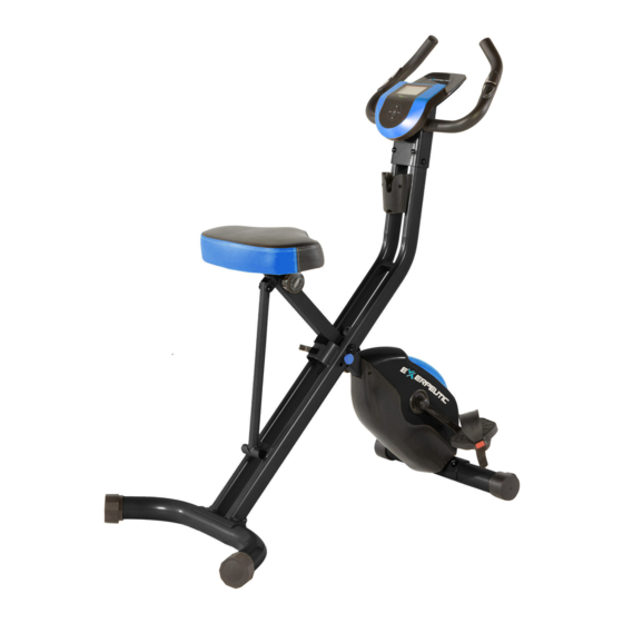
- Page 1 Folding Upright Bike with Pulse IMPORTANT: Read all instructions carefully before using this product. Retain this owner’s manual for future reference. The specifications of this product may vary from this photo, subject to change without notice. OWNER’S MANUAL 4103.2-112917...
- Page 2 PLEASE DO NOT RETURN THIS PRODUCT TO THE STORE. STOP. Contact customer service if you have any questions regarding assembly or proper operation of the machine. Email us at: Service@paradigmhw.com Or call us at: 1-844-641-7921 Hours: 8:00 am to 5:00 pm (PST) Daily...
-
Page 3: Table Of Contents
TABLE OF CONTENTS SERVICE ------------------------------------------------------------------------ 2 LABEL PLACEMENT --------------------------------------------------------- 3 IMPORTANT SAFETY GUIDELINES ------------------------------------ 4 OVERVIEW DRAWING ------------------------------------------------------ 5 PARTS LIST -------------------------------------------------------------------- 6 HARDWARE & TOOL PACK ------------------------------------------------ 8 ASSEMBLY --------------------------------------------------------------------- 9 CONSOLE FUNCTIONS ---------------------------------------------------- 14 STORAGE ----------------------------------------------------------------------- 17 OPERATIONS & ADJUSTMENTS ---------------------------------------- 18 TRANSPORT ------------------------------------------------------------------ MAINTENANCE &... -
Page 4: Service
SERVICE IMPORTANT: FOR NORTH AMERICA ONLY For damaged or defective product, questions, replacement parts or any other service support, please contact our customer service department by the below methods: For The Best Service, please Email: service@paradigmhw.com Response Time: 1-2 Business Days Emailing us with the information above will be the best method to receive a response during peak business hours Website:... -
Page 5: Label Placement
LABEL PLACEMENT... -
Page 6: Important Safety Guidelines
IMPORTANT SAFETY GUIDELINES Basic precautions should always be followed, including the following safety guidelines when using this equipment. Read all of the guidelines before using this equipment. 1. Before exercising and to avoid injuring your muscles, it is highly recommended that you perform warm-up exercises for each muscle group. -
Page 7: Overview Drawing
OVERVIEW DRAWING... -
Page 8: Parts List
PARTS LIST Description Description Front Frame 31 Front Stabilizer Ø50x1.5tx550L Rear Frame 32 C-ring Ø10 Rear Stabilizer 33 Flat Washer Ø8.2xØ16.8 Handlebar 34 Nylon Nut M8 Seat Post 35 Magnet Bracket Seat Cushion 36 Washer Ø6.2 Left Pedal 37 Speed Sensor Wire Right Pedal 38 Flywheel Computer... - Page 9 PARTS LIST Description Description 62 Holder 77 Handlebar End Cap Ø25.4 Round Phillips Head Screw Front Frame Support Tube End M4x10 Cap Ø22.2 64 Plastic Washer 79 Hand Pulse Sensor Wire 65 C-ring Ø15 80 Nut M6 66 Screw M4x10L 81 Screw M6x15 67 Rear Frame Support Tube 82 Hand Pulse Sensor...
-
Page 10: Hardware & Tool Pack
HARDWARE & TOOLS PACK... -
Page 11: Assembly
ASSEMBLY Figure A TOOL 13,15mm Wrench Front Stabilizer (31) Transport Wheels Step 1 1A. Frame Set Up: Extend the Front Frame (1) and the Rear Frame (2). Rest the Rear Frame Support Tube (67) into the hooked plate on the Front Frame (1). Align the upper pin holes of both frames. - Page 12 ASSEMBLY TOOLS PRE-INSTALLED HARDWARE (86) Right (84) Left 13-15mm Wrench Nylon Nut Nylon Nut 19mm Wrench Figure B Step 2 Tip: The Cranks, Pedals, Pedal Shafts, and the Pedal Straps are marked “R” for Right and “L” for Left. Note: Turn the Left Pedal (7) only in a COUNTER-CLOCKWISE direction. Turn the Right Pedal (8) only in a CLOCKWISE direction.
-
Page 13: Seat Post:
ASSEMBLY TOOL 5mm Allen Wrench with Phillips Screwdriver Step 3 Tip: The Seat Cushion (6) has 2 sets of adjustment holes. It is recommended that users between 5’1” – 5’6” use the holes towards the rear. It is recommended that users between 5’7” to 6’3” use the holes towards the front. -
Page 14: Computer
ASSEMBLY TOOL 5mm Allen Wrench with Phillips Screwdriver Figure C Figure D Step 4 Remove four Screws (75) from the Console (9) first. 4A Installing the Handlebar: Place the Handlebar (4) onto the Front Frame (1), Secure the Handlebar (4) onto the Front Frame (1) with four Flat Washers (33) and four Hexagon Socket Bolts (58). - Page 15 ASSEMBLY Step 5 5A. Power Adaptor Installation – Plug the small end of the AC Adaptor (91) into the Adaptor Wire (90) at the rear of the Left Cover (18), then plugging in the AC Adaptor (91) into an electrical outlet.
-
Page 16: Console Functions
CONSOLE FUNCTIONS Display Information: TIME----------------------------------------------------- 00:00-99:00 SPEED ------------------------------------------------- 0.0-99.9 MPH / KM DISTANCE (DIST) ----------------------------------- 0.0-999.9 ML CALORIES (CAL) ------------------------------------ 0.0-999.9 CAL ODOMETER (ODO) --------------------------------- 0-999.9 ML CONSOLE BUTTONS: Start/Stop Button: Starts and pauses workouts. Mode Button: Switches displayed workout values: MPH/KMPH DIST WATT... - Page 17 CONSOLE FUNCTIONS Quick Start: Pressing START at the user selection screen will take you into a “QUICKSTART” manual workout using the selected user profile. You can set a consistent resistance level for the entire workout with ˄ ˅ buttons. Workout Program: Challenge yourself with one of the 21 preset workout programs.
- Page 18 CONSOLE FUNCTIONS CONSOLE FEATURES: ˄ ˅ CHANGE UNITS OF MEASUREMENT: Pressing and holding for 3 seconds will reset the console display and will change the units between Metric (kilometers) & Imperial (miles). Pressing and holding the START button for 3 seconds will reset the console display. Shut Off: The Console will go into standby after 4 minutes of inactivity.
-
Page 19: Storage
STORAGE For your convenience, the bike can be folded up for storage. Remove the Safety Pin (22) from the upper pin hole on the Front Frame (1) Fold the Front and Rear frames together. Re-insert the Safety Pin (22) into the lower pin hole on the Front Frame (1) to secure the Front and Rear Frames (1,2) together. -
Page 20: Operations & Adjustments
OPERATIONS & ADJUSTMENTS Seat Height Adjustment Knob (14) Seat Post (5) Adjusting the Seat Height Loosen the Seat Height Adjustment Knob (14) by turning it counterclockwise. Pull AND hold to release the pin. While the Knob is being pulled, adjust the Seat Post (5) to the desired height. Release the Seat Height Adjustment Knob (14) to allow the pin to catch one of the holes along the Seat Post (5). - Page 21 OPERATIONS & ADJUSTMENTS Adjusting the Pedal Strap L mark The Left Pedal Strap (87) has an L marked on the strap (see Figure 1). Snap the slotted end of the Left Pedal Strap (87) onto the tab on the inside edge of the Left Pedal (7) (See Figures 2 and 3).
-
Page 22: Transport
TRANSPORT Transporting the Bike Hold the Handlebar (4) and tilt the bike forward until the wheels on the Front Stabilizer (31) make contact with the floor. Push or pull the unit to the desired location, then gently lower the Rear Stabilizer (3) back down to the ground. -
Page 23: Maintenance & Troubleshooting
MAINTENANCE & TROUBLESHOOTING MAINTENANCE Cleaning The bike can be cleaned with a soft, clean damp cloth. Do not use abrasives or solvents on the plastic parts. Wipe your perspiration off the bike after each use. Be careful not to get excessive moisture on the computer display panel as this might cause an electrical hazard or the electronics to fail. -
Page 24: Warranty
WARRANTY MANUFACTURER’S LIMITED WARRANTY Paradigm Health & Wellness warrants to the original purchaser that this product is free from defects in material and workmanship when used for the purpose intended, under the conditions that it has been installed and operated in accordance with Paradigm’s Owner’s Manual. -
Page 25: Parts Request Form
PARTS REQUEST FORM Paradigm Health & Wellness, Inc. EMAIL THIS FORM WITH YOUR RECEIPT OF PURCHASE TO Service@paradigmhw.com NAME:______________________________________________________________________ ADDRESS:__________________________________________________________________ CITY:________________________ STATE:_____________ ZIP:________________________ TELEPHONE: (Day)_________________________________________________________ (Night)________________________________________________________ SERIAL#:____________________________________________________________________ MODEL#:____________________________________________________________________ PURCHASE DATE:____________________________________________________________ PLACE OF PURCHASE:________________________________________________________ PART # DESCRIPTION “YOUR ORDER WILL BE PROCESSED WITHIN 3 BUSINESS DAYS” *This form can also be faxed to #: 626-810-2166...
Need help?
Do you have a question about the Folding Upright Bike with Pulse and is the answer not in the manual?
Questions and answers
My bike computer is not working.
If the bike computer on the Exerpeutic Folding Upright Bike with Pulse is not displaying, try the following solutions:
1. Check the Wiring – Remove the Console Cover and verify that the wire from the computer console is properly connected to the wires from the rear frame.
2. Check Battery Positioning – Ensure the batteries are correctly placed and that the battery springs are in proper contact with the batteries.
3. Replace Batteries – If the batteries are dead, replace them with new ones.
If the issue persists, contact customer service for further assistance.
This answer is automatically generated