Table of Contents
Advertisement
IM
MPORTANT
Re
etain this o
Th
he specific
wi
ithout Not
7150
.4‐10121
16
Des
sk B
T: Read all
l instructi
ions caref
owner's m
manual for
r future re
cations of
f this prod
duct may v
tice
OW
WNER
R'S M
Bike
e
fully befor
re using th
ference.
vary from
this photo
MANUA
AL
his produc
ct.
o, subject
to change e
Advertisement
Table of Contents

Related Manuals for Exerpeutic WorkFit


Summary of Contents for Exerpeutic WorkFit
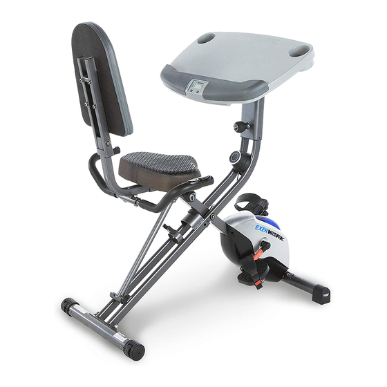
- Page 1 sk B Bike e MPORTANT T: Read all l instructi ions caref fully befor re using th his produc etain this o owner’s m manual for r future re ference. he specific cations of f this prod duct may v vary from this photo o, subject...
-
Page 3: Table Of Contents
TABLE OF CONTENTS SERVICE------------------------------------------------------------------------------ 2 LABEL PLACEMENT--------------------------------------------------------------- 3 IMPORTANT SAFETY GUIDELINES------------------------------------------ 4 OVERVIEW DRAWING------------------------------------------------------------ 5 PARTS LIST-------------------------------------------------------------------------- 6 HARDWARE & TOOLS PACK--------------------------------------------------- 8 ASSEMBLY--------------------------------------------------------------------------- 9 CONSOLE---------------------------------------------------------------------------- 15 ADJUSTMENTS-------------------------------------------------------------------- 16 BATTERY INSTALLATION------------------------------------------------------- 20 STORAGE----------------------------------------------------------------------------- 21 TRANSPORTING THE BIKE----------------------------------------------------- 22 MAINTENANCE & TROUBLE SHOOTING----------------------------------- 23 WARRANTY-------------------------------------------------------------------------- 24 PART REQUEST FORM---------------------------------------------------------- 25... -
Page 4: Service
SERVICE IMPORTANT: FOR NORTH AMERICA ONLY For damaged or defective product, questions, replacement parts or any other service support, please contact our customer service department (8:00 AM - 5:00 PM Pacific Standard Time, Daily) by the below methods: For Best Service Email: Service@paradigmhw.com Website: www.paradigmhw.com... -
Page 5: Label Placement
LABEL PLACEMENT ... -
Page 6: Important Safety Guidelines
IMPORTANT SAFETY GUIDELINES Basic precautions should always be followed when using this equipment. Read all instructions before using this equipment which include the following safety instructions: Read all the instructions in this manual and do warm up exercises before using this equipment. Before exercising, and in order to avoid injuring your muscles, it is recommended that you perform warm-up exercises for every muscle group. -
Page 7: Overview Drawing
OVERVIEW DRAWING... -
Page 8: Parts List
PARTS LIST Part # Description Part # Description Rear Frame Washer Ø6.2 Front Frame Sensor with Wire Rear Stabilizer Flywheel Ø195 Belt Wheel with Crank Axle Handlebar Ø155 Seat Post Bearing Bracket Seat Wave Washer Left Pedal Bearing 6003RS Left Pedal Strap C-ring Ø17 Belt Wheel with Crank Axle Right Pedal... - Page 9 PARTS LIST Description Part # Description Front Stabilizer End Cap Drilling Screw M4x10 Spring Washer Ø 6.2 Carriage Bolt M8*45 Hexagon Socket Bolt M8x80L 1 Spring Washer Ø8.2 Hexagon Socket Bolt M8x43L 1 Hexagon Socket Bolt M8*25 Handlebar End Cap Ø25.4 Washer Ø25xØ8.2 Front Frame Support Tube Plastic Washer...
-
Page 10: Hardware & Tools Pack
HAR R DWAR R E & T TOOLS PACK K... -
Page 11: Assembly
ASSEMBLY Tool: 13-15mm Wrench 1.1 Stand Up the Machine Extend the Front Frame (2) and the Rear Frame (1). Rest the Rear Frame Support Tube (67) into the hooked plate on the Rear Frame (1). Align the upper pin holes at the center of the bike and insert the Safety Pin (22) into the Front Frame (2) and the Rear Frame (1) to lock the frames in place. - Page 12 ASSEMBLY Important: Make sure the right pedal matches up with the right crank and the left pedal matches up with the left crank. If reversed the cranks may become damaged or stripped. Important: Screw the Right Pedal (8) into the Right clockwise Crank (24) in a direction.
-
Page 13: Seat Post (
ASSEMBLY Tool: 5mm Allen Wrench With Phillips Screwdriver Step 3. Seat Installation The Seat (6) has 2 sets of adjustment holes. It is recommended that users between 5’1” – 5’6” use the holes towards the rear of the Seat (6). It is recommended that users between 5’7”... -
Page 14: Backrest Frame 1
ASSEMBLY Tool: 13-15mm Wrench 5mm Allen Wrench With Phillips Screwdriver Step 4. Backrest Frame and Backrest Installation Attach the Backrest Frame (9) onto the Seat Post (5) using the two Flat Washers (33), two Nylon Nuts (34), and two Carriage Bolts (106). Simultaneously tighten the bolts and nuts with the 13-15mm Wrench and the 5mm Allen Wrench with Phillips Screwdriver provided. -
Page 15: Rear Supporting Tube 1
ASSEMBLY Tool: 5mm Allen Wrench With Phillips Screwdriver 13-15mm Wrench Step 5. Handlebar Installation Attach the Handlebar (4) onto the Rear Supporting Tube (15) using, two Curve Washers (30), two Spring Washers (102), and two Carriage Bolts (101). Then tighten the bolts with the 5mm Allen Wrench with Phillips Screwdriver provided. - Page 16 ASSEMBLY Tool: 5mm Allen Wrench 13-15mm Wrench With Phillips Screwdriver Step 6. Desk Installation Align the bolt holes of the U shaped bracket on the underside of the Desk (88) with the holes on the bracket at the top of the Desk Mount (87). Insert the Plastic Bushing (92) into the bracket of the Desk Mount (87) as shown in Fig.
-
Page 17: Console
CONSO SPECIF FICATIONS TIME --- -------------- -------------- ---------- 0 0:00-99:59 MIN:SEC SPEED ------------- -------------- ---------- 0 0.0-999.9 M ML/H DISTAN CE --------- -------------- ---------- 0.0-999.9 M CALORI IE ---------- -------------- ---------- 0 0.0-999.9 K KCAL ODOME ETER ------ --------------- ---------- 0 0.0-999.9 M PULSE --------------... -
Page 18: Adjustments
ADJUSTMENTS Increase Decrease Adjusting the Tension Control Knob To increase the resistance, turn the Tension Control Knob (13) in a clockwise direction. To decrease the resistance, turn the Tension Control Knob (13) in a counterclockwise direction. Adjusting the Seat Height Turn the seat Adjustment Knob (14) in a counter-clockwise direction and pull to release the Seat Post (5). - Page 19 ADJUSTMENTS Adjusting the Backrest The Rear Supporting Tube (15) can be adjusted between 3 different positions: 1. Users between the height of 5’1” and 5’3” may want to use position 1, as shown in FIG. A. 2. Users between the height of 5’4” to 5’11” may want to use position 2 as shown in FIG.
-
Page 20: Front Stabilizer 1
ADJUSTMENTS Leveling the Machine. If you experience a “wobble” while exercising, do the following: Make sure the Front Stabilizer End Caps (73) are all in contact with the floor.Turn the Front Stabilizer End Caps (73) in a counter-clockwise direction to raise the Front Frame (2). Turn the Front Stabilizer End Caps (73) in a clockwise direction to lower the Front Frame (2). - Page 21 ADJUSTMENTS Adjusting the Desk Height Adjusting the Desk Range 1. Loosen the Long Adjustment Knob 1. Loosen the Slide Knob (95) by (119) by turning it counter turning it counter-clockwise. clockwise. 2. Shift the Desk (88) forward or 2. Pull the Long Adjustment Knob backwards to the desired position.
-
Page 22: Battery Installation
BATTERY INSTALLATION HOW TO INSTALL THE BATTERIES: 1. Remove the battery cover on the back of the computer. 2. Place two "SIZE-AAA" batteries into the battery housing. 3. Ensure that the batteries are correctly positioned and that the battery springs are in proper contact with batteries. -
Page 23: Storage
STORA For your r convenie nce, the bi ike can be folded up for storage e when no ot in use. gle the Des sk (88) to i ts lowest p position. Slid de the Des k (88) to it s furthest f forward po osition. -
Page 24: Transporting The Bike
ANSPO ORTING G THE BIKE Transpo orting the Bike 1. Adjus st the Bike to Storage e Mode, se ee page 23 2. Hold onto the D and tilt the e bike onto o to the wh heels of th he Rear St Desk (88) tabilizer... -
Page 25: Maintenance & Trouble Shooting
MAINTENANCE & TROUBLE SHOOTING MAINTENANCE Cleaning The bike can be cleaned with a soft cloth and a mild detergent. Do not use abrasives or solvents on the plastic parts. Be sure to wipe your perspiration off the bike after each use. Be careful to not get excessive moisture on the console display panel as this may cause an electrical hazard or the electronics to fail. -
Page 26: Warranty
WARRANTY MANUFACTURER’S LIMITED WARRANTY Paradigm Health & Wellness warrants to the original purchaser that this product is free from defects in material and workmanship when used for the purpose intended, under the conditions that it has been installed and operated in accordance with Paradigm’s Owner’s Manual. -
Page 27: Part Request Form
PART REQUEST FORM Paradigm Health & Wellness, Inc EMAIL THIS FORM WITH YOUR RECIEPT OF PURCHASE TO Service@paradigmhw.com NAME: _______________________________________________________ ADDRESS: ____________________________________________________ CITY ______________ STATE ______________ ZIP ___________________ TELEPHONE: (Day) _____________________________________________ (Night) ____________________________________________ SERIAL#: _____________________________________________________ MODEL#: _____________________________________________________ PURCHASE DATE: ______________________________________________ PLACE OF PURCHASE: _________________________________________ PART # DESCRIPTION...
Need help?
Do you have a question about the WorkFit and is the answer not in the manual?
Questions and answers
The strap hole broke off the right pedal. Can I buy a new right pedal?