Table of Contents
Advertisement
Advertisement
Table of Contents

Related Manuals for JUMO eTron M 100


Summary of Contents for JUMO eTron M 100
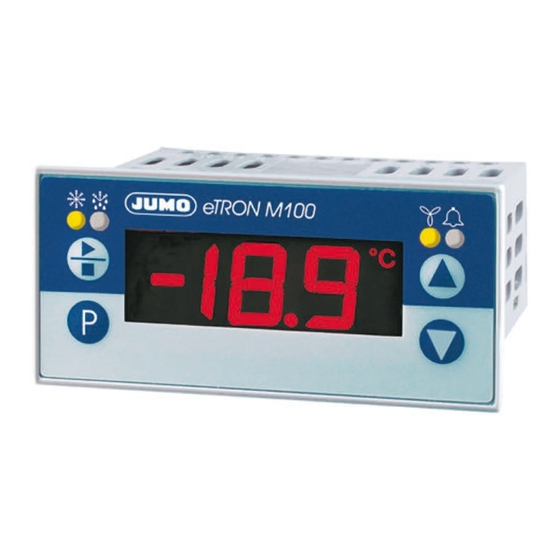
- Page 1 Electronic Refrigeration Controller B 70.1061.0 Operating Instructions 2009-04-10...
- Page 2 Overview of operation Process value display Cold store temperature (analog input 1) Code settable through Setup Evaporator temperature Display alternates > 3 seconds (analog input 2) increase decrease Residual time of current defrosting Parameter level All parameters can be altered here Operator level (no parameters enabled in factory setting)
-
Page 3: Table Of Contents
Contents Identifying the instrument version ..........4 Mounting . - Page 4 5.10 Date and time ............. . . 30 5.11 Servicing, operating hours counter .
- Page 5 Contents...
-
Page 6: Identifying The Instrument Version
2009-04-10 1 Identifying the instrument version Identifying the instrument version The nameplate is glued onto the housing top. The supply voltage must correspond to the voltage given on the nameplate. All necessary settings are described in these operating instructions. Any manipulations that are not described in the operating instructions (or even expressly forbidden) will endanger your rights under the instrument warranty ! If you have any problems, please contact the nearest subsidiary or the head office. - Page 7 701061 Basic version with 2 analog inputs and 3 relay outputs Basic type extensions factory-set, configurable configuration to customer specification Option 1 not available alarm buzzer alarm contact, changeover (SPDT) 16A/250V Option 2 not available RS485 interface data logger, real-time clock and RS485 interface Supply voltage 12 —...
-
Page 8: Mounting
2009-04-10 2 Mounting Mounting Pull mounting frame off the instrument. Insert the instrument from the front into the panel cut-out. Make sure that the bezel seal is seated correctly. From the back, push the mounting frame onto the instrument housing, compressing the spring clips until the lugs have evenly snapped into place top and bottom. -
Page 9: Electrical Connection
Electrical connection 3.1 Installation notes The choice of cable, the installation, the fusing and the electrical connection must conform to the requirements of VDE 0100 “Regulations on the Installation of Power Circuits with Nominal Voltages below 1000 V” or the appropriate local regulations. -
Page 10: Connection Diagram
2009-04-10 3 Electrical connection 3.3 Connection diagram 1. The electrical connection must only be carried out by qualified personnel. 2. For shock-hazard protection, the instrument must only be connected to extra-low voltages which comply with SELV or PELV definitions, because supply voltage and analog inputs are not electrically isolated from one another ! Type 701061/XXX-XX Option 1:... -
Page 11: Commissioning The Instrument
Commissioning the instrument 4.1 Displays and controls LC display 3-character nine-segment display, 13 mm high, and symbols for the temperature unit, hr, min, and sec, with red background lighting. Once the supply is switched on, all the segments light up and stay on for 5 seconds. -
Page 12: Process Value Display (After Switch-On)
2009-04-10 4 Commissioning the instrument Apply the supply voltage, all segments light up five seconds long (for testing the segments). When everything has been connected up correctly to the instrument, it will show the current temperature at analog input 1. With the Data logger option, is shown briefly after switching on. -
Page 13: Canceling Editing
Acknowledge with , the value blinks , prompting your entry. Use the keys to set the value within the specified range. The longer the key is pressed, the faster the value will change. Acknowledge the setting with , the new value is stored, and the display again switches between parameter name and value. -
Page 14: Parameter Level
2009-04-10 5 Parameter level Parameter level Where appropriate, the full parameter names have been added in brackets, to explain their abbreviated forms in the display. All parameters for the maximum expansion level are listed in the table below. Depending on the instrument version (see data sheet), parameters which are not required are switched out of display. Value range Parameter Meaning from...factory-set...to... - Page 15 Value range Parameter Meaning from...factory-set...to Ω Lead compensation resistance, analog input 1 (offset resistance 1) 0.0 ... 0.0 ... 99.9 This value serves to compensate the resistance of the probe cable; it is dependent on the cable length. For an optimum temperature measurement, the resistance value of the probe cable must be entered here.
-
Page 16: Binary Input
2009-04-10 5 Parameter level Value range Parameter Meaning from...factory-set...to Ω Lead compensation resistance, analog input 2 (offset resistance 2) 0.0 ... 0.0 ... 99.9 This value serves to compensate the resistance of the probe cable; it is dependent on the cable length. For an optimum temperature measurement, the resistance value of the probe cable must be entered here. -
Page 17: Controller
Value range Parameter Meaning from...factory-set...to 5.3 Controller Ex-factory, the controller is set to "Cooling". For the special “Cooling + Heating” function, the fan relay is used for heating. Contr. type (tyPe) with above/below measured value (e.g. probe break) 0, 1, 2 0 : Cooling contr. - Page 18 2009-04-10 5 Parameter level Value range Parameter Meaning from...factory-set...to Hysteresis 0.0...1.0...50.0 °C For cooling and freezing, the hysteresis lies above the selected setpoint. 0.0...1.8...90.0 °F For the “Cooling + Heating” function, the hysteresis is above or below the selected setpoint, like a window function. Cooling / Freezing Cooling and Heating T/°C...
- Page 19 Value range Parameter Meaning from...factory-set...to Minimum Here you can set the minimum time for which e. g. the cooling unit 0 ... 999 sec switch-on time (relay ) must be switched on or remain switched off. (time on) Please refer to the manufacturer's specifications for the cooling unit that is used.
-
Page 20: Defrosting (Cyclic)
2009-04-10 5 Parameter level Value range Parameter Meaning from...factory-set...to 5.4 Defrosting (cyclic) Cooling operation Defrosting operation T/°C Analog input 2 Analog input 1 (evaporator) (cold store) SP = 8 °C The starting behavior after power ON depends on the controller type Relay and the Power on parameter... - Page 21 Value range Parameter Meaning from...factory-set...to Defrosting type EL, GAS EL = electrical/circulating air: The cooling relay is switched off, and the defrosting relay is energized to defrost the evaporator by means of heater bars or circulating warm air. GAS = hot-gas defrosting: In this case, the cooling relay remains switched on during defrosting.
- Page 22 2009-04-10 5 Parameter level Value range Parameter Meaning from...factory-set...to Defrosting duration 0: no time limit The relay is energized during the defrosting time. Depending on the defrosting type 0 ...30... 999 d.tY that has been set, “electrical/circulating air” or “hot gas” is used for defrosting. minutes Defrosting ends when the following has occurred: 1.
- Page 23 Value range Parameter Meaning from...factory-set...to Time 1 Hours and minutes can be separated by a decimal point. switched off: off The digit behind the decimal point represents a 10-minute step. 0.0... 23.5 hrs (defrosting time 1) Example: 23.5 signifies: 23:50 hrs Time 2 0.1 signifies: 00:10 hrs (defrosting time 2)
-
Page 24: Switching Behavior Of The Fan Function
2009-04-10 5 Parameter level 5.5 Switching behavior of the fan function Cooling operation T/°C Analog input 1 (cold store) SP = 8 °C Relay energized Cooling Cooling Cooling de-energized Defrosting operation Relay energized Defrosting de-energized Defrosting time Defrosting function:cyclic Cycle time : Analog input 2 Run-up/ (evaporator temperature) - Page 25 Value range Parameter Meaning from...factory-set...to Fan function (see picture above) 0, 1, 2 0: fan runs with relay only 1: fan runs continuously except for defrosting (relay 2: fan runs during cooling (relay ) or defrosting (relay Run-up/run-down delay of fan (Fan running function) off, on has the hysteresis F.Hy, remains generally locked during drip-off time.
-
Page 26: Alarms
2009-04-10 5 Parameter level Value range Parameter Meaning from...factory-set...to Fan run-up delay after defrosting (Fan deLay) 0 …30... 99 minutes After defrosting, the activity of the fan relay will be delayed for the time that was set. This has a higher priority than the run-up delay activated through F.ru=on, which would possibly switch the fan on earlier. - Page 27 Value range Parameter Meaning from...factory-set...to Alarm signaling (ALarm Function) 0, 1, 2, 3, 0: Relay is energized (alarm buzzer ON), with absolute alarm limits 1: Relay is de-energized (alarm buzzer OFF), with absolute alarm limits Absolute temperatures AL.L and AL.H AL.F = 0 =1°C energized...
- Page 28 2009-04-10 5 Parameter level Value range Parameter Meaning from...factory-set...to Low alarm limit (ALarm Low) For AL.F = 0 and 1: If the process value at the analog input 1 (in.1, cold store) goes below this limit: -200 ... -50 ... +500 °C 1.
-
Page 29: Lc Display
Value range Parameter Meaning from...factory-set...to Alarm suppression time (ALarm delay time) 0 ...5... 999 min An alarm from is suppressed in the display for this time, the relay or the alarm buzzer is also inactive. If an alarm is present for longer than , then it is displayed and the relay the alarm buzzer is active. -
Page 30: Interface
Alarm display (display Alarm) off, on off: do not display alarms on: display alarms 5.8 Interface B 70.1061.2 Interface description on CD und www.jumo.net Device address 1...255 Data format 0, 1, 2, 3 0 means: 8 data bits, 1 stop bit, no parity... -
Page 31: Data Logger
Value range Parameter Meaning from...factory-set...to Baud rate 9.6, 19.2, 38.4 9.6 means: 9600 bps 19.2 means: 19200 bps 38.4 means: 38400 bps 5.9 Data logger The data logger saves 11263 data sets to a ring memory which overwrites the oldest data with the most recent ones when the memory is full. -
Page 32: Date And Time
2009-04-10 5 Parameter level Value range Parameter Meaning from...factory-set...to 5.10 Date and time Date Year 7...99 Millennium and century are permanently set to 20. The last two digits of the year can be adjusted. Date Month 1...12 Date Day 1...31 Date Hour 0...23 Date Minute... -
Page 33: Servicing, Operating Hours Counter
Value range Parameter Meaning from...factory-set...to 5.11 Servicing, operating hours counter Time between services (timer Service interval) 0 ... 999 days The time period after which the cooling unit is due for servicing (e.g. oil change or coolant test) is set here. The sum of all the active cooling-unit runtimes is saved here (i.e. - Page 34 2009-04-10 5 Parameter level Value range Parameter Meaning from...factory-set...to Current service counter for the connected cooling unit (timer Service counter) 0 ... 999 days The sum of all the active cooling-unit runtimes is accumulated here (i.e. the times in over 24 hrs, days are which the cooling relay was energized) from those which have gone by since the last displayed: service.
- Page 35 5 Parameter level 2009-04-10...
-
Page 36: Operator Level
2009-04-10 6 Operator level Operator level This level covers all parameters that are accessible (not locked by a code) to the operating personnel, for instance. Ex-factory, no parameters are available at this level. In the picture below, the parameters SP and HYS are configured at the operator level. Any parameter (up to eight 8) can be enabled at this level through the setup program. -
Page 37: Technical Data
Technical data Analog input 1 Designation Measuring range Tolerance Detection of ... and 2 in % of measuring range span, probe probe temperature effect short- break circuit RTDs Pt100 EN 60751 -200 to +600°C 0.05% (±0.4°C),100ppm/°C Pt1000 EN 60751 -200 to +600°C 0.05% (±0.4°C),100ppm/°C KTY1X-6 -50 to +100 °C... - Page 38 2009-04-10 7 Technical data Environmental influences Ambient temperature range 0 to +55°C Storage temperature range -40 to +70°C ≤85% rel. humidity, no condensation Climatic conditions Shock und vibration DIN EN 60068-2-6 schedule C.2, Frequency-Range: 10 to 55 Hz Acceleration: 20 m/s (2g) Care of the front panel The front panel can be cleaned with normal commercial washing, rinsing and cleaning...
- Page 39 Gold Cap capacitor buffers the clock time without a supply voltage for about 20 days. Technical and functional as per EN 12830 and EN 13485. characteristics of temperature recording devices or thermometers Approvals UL approvals are only valid for mass-production units with the JUMO symbol 7 Technical data 2009-04-10...
-
Page 40: Setup Program
2009-04-10 7 Technical data 7.1 Setup program This program and the interface with adapter can be supplied as accessories. They offer the user the following advantages: easy and convenient parameterization and archiving from a PC simple duplication of parameters for instruments of the same type entry of a linearization table reading out data sets from the data logger. -
Page 41: Transferring Measurements From The Data Logger To The Pc
7.4 Transferring measurements from the data logger to the PC The data logger saves 11263 data sets to a ring memory which overwrites the oldest data with the most recent ones when the memory is full. Transfer data from device Choose data logger Click OK, the data will be read out Click table view, the table on the right will be shown... -
Page 42: Processing Measurements In Excel 1
2009-04-10 7 Technical data 7.5 Processing measurements in Excel Execute Extras => data logger => Save in menu bar Enter Semicolon as a separator Click Save as Save as 01_02_07.txt Execute File => Open in the Excel menu bar Select all files, otherwise the txt file will not be shown in the selection window Select 01_02_07.txt Even if the wizard comes up with an error message, clicking OK will start the text conversion wizard. - Page 43 Tab stop and semicolon must have a check mark Click Continue and enter a point as a separator, instead of the comma 7 Technical data 2009-04-10...
- Page 44 2009-04-10 7 Technical data The table can now be processed in Excel and saved in the Excel file format (.xls).
-
Page 45: Alarm And Error Messages
Alarm and error messages The following alarm messages can be shown in alternation with the temperature display: Alarm display Cause Remedy Service interval run down Carry out service The selected time for the maintenance At the parameter level, reset manually to 0 of a heating or cooling unit has run down Chapter 4 “Commissioning the instrument”... - Page 46 2009-04-10 8 Alarm and error messages Error message Cause Remedy Gone above measured value Check probe and connecting cable for damage or The measured value is too large, is short-circuit outside the measurement range, or a Check whether the correct probe has been set or probe break has occurred.
-
Page 47: Troubleshooting
The flash memory of the data logger The instrument must be returned to JUMO for repair. is faulty. The chip for the real-time clock is faulty. 8.1 Troubleshooting What is happening? Cause / Remedy Information Communication with the unit inter- Interface settings of the unit and PC do Chapter 7.1 “Setup program”... - Page 48 JUMO GmbH & Co. KG JUMO Instrument Co. Ltd. JUMO Process Control, Inc. Street adress: JUMO House 8 Technology Boulevard Moritz-Juchheim-Straße 1 Temple Bank, Riverway Canastota, NY 13032, USA 36039 Fulda, Germany Harlow, Essex CM20 2TT, UK Phone: 315-697-JUMO Delivery address:...
Need help?
Do you have a question about the eTron M 100 and is the answer not in the manual?
Questions and answers