Advertisement
Table of Contents
- 1 Table of Contents
- 2 Warning Decal Placement
- 3 Important Precautions
- 4 Before You Begin
- 5 Part Identification Chart
- 6 Assembly
- 7 How to Use the Elliptical
- 8 Maintenance and Troubleshooting
- 9 Exercise Guidelines
- 10 Part List
- 11 Exploded Drawing
- 12 Ordering Replacement Parts
- 13 Recycling Information
- Download this manual
Model No. PFEVEL39717.0
Serial No.
Write the serial number in the space
above for reference.
Number
CUSTOMER SERVICE
UNITED KINGDOM
Call: 0330 123 1045
From Ireland: 053 92 36102
Website: iconsupport.eu
E-mail: csuk@iconeurope.com
Write:
ICON Health & Fitness, Ltd.
Unit 4, Westgate Court
Silkwood Park
OSSETT
WF5 9TT
UNITED KINGDOM
AUSTRALIA
Call: 1800 993 770
E-mail: australiacc@iconfitness.com
Write:
ICON Health & Fitness
PO Box 635
WINSTON HILLS NSW 2153
AUSTRALIA
CAUTION
Read all precautions and
instructions in this manual before
using this equipment. Keep this
manual for future reference.
Serial
Decal
USER'S MANUAL
iconeurope.com
Advertisement
Table of Contents

Related Manuals for Pro-Form ENDURANCE 320 E


Summary of Contents for Pro-Form ENDURANCE 320 E
- Page 1 Model No. PFEVEL39717.0 Serial No. USER’S MANUAL Write the serial number in the space above for reference. Serial Number Decal CUSTOMER SERVICE UNITED KINGDOM Call: 0330 123 1045 From Ireland: 053 92 36102 Website: iconsupport.eu E-mail: csuk@iconeurope.com Write: ICON Health & Fitness, Ltd. Unit 4, Westgate Court Silkwood Park OSSETT...
-
Page 2: Table Of Contents
TABLE OF CONTENTS WARNING DECAL PLACEMENT ............. . .2 IMPORTANT PRECAUTIONS . -
Page 3: Important Precautions
IMPORTANT PRECAUTIONS WARNING: To reduce the risk of serious injury, read all important precautions and instructions in this manual and all warnings on your elliptical before using your elliptical. ICON assumes no responsibility for personal injury or property damage sustained by or through the use of this product. -
Page 4: Before You Begin
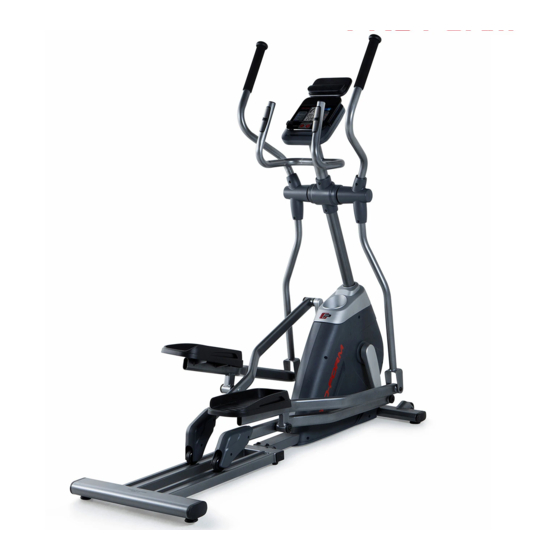
Thank you for selecting the revolutionary PROFORM reading this manual, please see the front cover of this ® ENDURANCE 320 E elliptical. The ENDURANCE 320 E manual. To help us assist you, note the product model elliptical provides an impressive selection of features number and serial number before contacting us. -
Page 5: Part Identification Chart
PART IDENTIFICATION CHART Use the drawings below to identify the small parts needed for assembly. The number in parentheses below each drawing is the key number of the part, from the PART LIST near the end of this manual. The number following the key number is the quantity needed for assembly. -
Page 6: Assembly
ASSEMBLY • Assembly requires two persons. • In addition to the included tool(s), assembly requires the following tools: • Place all parts in a cleared area and remove the one Phillips screwdriver packing materials. Do not dispose of the packing materials until you finish all assembly steps. -
Page 7: Onto The Upright
3. With the help of a second person, place some of the packing materials (not shown) under the rear of the Frame (1). Attach the Track (11) to the Frame (1) with four M10 x 20mm Screws (74), two M10 x 38mm Screws (75), and six M10 Washers (64) as shown;... -
Page 8: The Frame (1
5. Tip: Avoid pinching the Main Wire (32). Slide the Upright (2) onto the Frame (1). Avoid pinching the Attach the Upright (2) with three M10 x 20mm Main Wire (32) Screws (74), three M10 Split Washers (80), and three M10 Curved Washers (62) as shown; do not fully tighten the Screws yet. - Page 9 7. Identify the Right Upper Body Arm (3) and the Right Upper Body Leg (5), and orient them as shown. Insert the Right Upper Body Arm (3) into the Right Upper Body Leg (5). Attach the Right Upper Body Arm with three M8 x 38mm Bolts (59) and three M8 Locknuts (60);...
- Page 10 9. Identify a set of Pivot Covers A and B (85, 86) and orient them as shown. Press the Pivot Covers A and B (85, 86) together around the Right Upper Body Arm (3) and Right Upper Body Leg (5). Attach them with four M4 x 16mm Self-tapping Screws (57);...
- Page 11 11. Apply grease to the right Crank Arm (13). Identify the Right Roller Arm (7) and orient it as shown. Attach the Right Roller Arm (7) to the right Crank Arm (13) with an M8 x 20mm Screw (61), an Grease Axle Cover (44), and an M8 Washer (63).
- Page 12 13. Apply grease to an M6 Bolt Set (67). Attach the Right Pedal Arm (9) to the Right Upper Body Leg (5) with the M6 Bolt Set (67). Attach the Left Pedal Arm (10) to the Left Upper Body Leg (6) in the same way. Grease 14.
- Page 13 15. Remove and discard the wire tie on the Main Wire (32). While a second person holds the Console (30) near the Upright (2), plug the Main Wire (32) and the Pulse Wire (31) into the matching recep- Avoid pinching tacles on the back of the Console.
-
Page 14: How To Use The Elliptical
HOW TO USE THE ELLIPTICAL HOW TO MOVE THE ELLIPTICAL HOW TO LEVEL THE ELLIPTICAL Due to the size and weight of the elliptical, moving If the elliptical rocks it requires two persons. Stand in front of the elliptical, slightly on your floor hold the upright, and place one foot against one of the during use, turn one wheels. - Page 15 HOW TO EXERCISE ON THE ELLIPTICAL To mount the elliptical, hold the handlebars or the upper body arms and step onto the pedal that is in the Upper lower position. Then, step onto the other pedal. Push Body Arms the pedals until they begin to move with a continuous motion.
- Page 16 CONSOLE DIAGRAM FEATURES OF THE CONSOLE resistance of the pedals and prompts you to maintain a target speed as it guides you through an effective The advanced console offers an array of features workout. designed to make your workouts more effective and enjoyable.
- Page 17 HOW TO USE THE MANUAL MODE The upper display—This display will show your pedal- 1. Turn on the console. ing speed in revolutions per minute (RPM) and your Press any button or begin pedaling to turn on the power output in watts. The console.
- Page 18 To pause the console, stop pedaling. When the When your pulse is detected, your heart rate will be console is paused, the displays will pause. To shown in the upper display. For the most accurate continue your workout, simply resume pedaling. heart rate reading, hold the contacts for at least 15 seconds.
- Page 19 HOW TO USE A PRESET WORKOUT few RPMs of the target speed for the segment. The solid bars represent your actual pedaling speed. 1. Turn on the console. As you exercise, keep your pedaling speed Press any button or begin pedaling to turn on the within the target zone for the current segment by console.
- Page 20 HOW TO USE THE SOUND SYSTEM HOW TO CONNECT YOUR TABLET TO THE CONSOLE To play music or audio books through the console sound system while you exercise, plug a 3.5 mm male The console supports BLUETOOTH connections to to 3.5 mm male audio cable (not included) into the tablets via the iFit Bluetooth Tablet app and to compat- jack on the console and into a jack on your personal ible heart rate monitors.
- Page 21 5. Disconnect your tablet from the console if THE SETTINGS MODE desired. The console features a settings mode that allows you To disconnect your tablet from the console, first to select a unit of measurement for the console and to select the disconnect option in the iFit Bluetooth view console usage information.
-
Page 22: Maintenance And Troubleshooting
MAINTENANCE AND TROUBLESHOOTING MAINTENANCE To adjust the reed switch, first use a Regular maintenance is important for optimal standard screw- performance and to reduce wear. Inspect and properly driver and carefully tighten all parts each time the elliptical is used. pry the Accessory Replace any worn parts immediately. - Page 23 HOW TO ADJUST THE DRIVE BELT See EXPLODED DRAWING A on page 26. Identify the Right and Left Shields (48, 49). Remove the If the pedals slip while you are pedaling, even while M4 x 16mm Screws (56) and the M4 x 16mm Self- the resistance is adjusted to the highest level, the drive tapping Screws (57) from the Right and Left Shields;...
-
Page 24: Exercise Guidelines
EXERCISE GUIDELINES Burning Fat—To burn fat effectively, you must exer- WARNING: cise at a low intensity level for a sustained period of Before beginning this time. During the first few minutes of exercise, your or any exercise program, consult your physi- body uses carbohydrate calories for energy. -
Page 25: Part List
PART LIST Model No. PFEVEL39717.0 R0717A Key No. Qty. Description Key No. Qty. Description Frame Accessory Tray Upright Front Upright Cover Right Upper Body Arm Outer Crank Cover Left Upper Body Arm Inner Crank Cover Right Upper Body Leg Rear Upright Cover Left Upper Body Leg Drive Belt Right Roller Arm... -
Page 26: Exploded Drawing
EXPLODED DRAWING A Model No. PFEVEL39717.0 R0717A... - Page 27 EXPLODED DRAWING B Model No. PFEVEL39717.0 R0717A...
-
Page 28: Ordering Replacement Parts
ORDERING REPLACEMENT PARTS To order replacement parts, please see the front cover of this manual. To help us assist you, be prepared to provide the following information when contacting us: • the model number and serial number of the product (see the front cover of this manual) •...
Need help?
Do you have a question about the ENDURANCE 320 E and is the answer not in the manual?
Questions and answers