Table of Contents
Advertisement
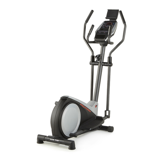
Model No. PFEVEL39616.0
Serial No.
USER'S MANUAL
Write the serial number in the space
above for reference.
Serial Number
Decal
CUSTOMER SERVICE
UNITED KINGDOM
Call: 0330 123 1045
From Ireland: 053 92 36102
Website: www.iconsupport.eu
E-mail: csuk@iconeurope.com
Write:
ICON Health & Fitness, Ltd.
Unit 4, Westgate Court
Silkwood Park
OSSETT
WF5 9TT
UNITED KINGDOM
AUSTRALIA
Call: 1800 993 770
E-mail: australiacc@iconfitness.com
Write:
ICON Health & Fitness
PO Box 635
WINSTON HILLS NSW 2153
AUSTRALIA
CAUTION
Read all precautions and
instructions in this manual before
using this equipment. Keep this
manual for future reference.
www.iconeurope.com
Advertisement
Table of Contents

Related Manuals for Pro-Form 325 CSE


Summary of Contents for Pro-Form 325 CSE
- Page 1 Model No. PFEVEL39616.0 Serial No. USER’S MANUAL Write the serial number in the space above for reference. Serial Number Decal CUSTOMER SERVICE UNITED KINGDOM Call: 0330 123 1045 From Ireland: 053 92 36102 Website: www.iconsupport.eu E-mail: csuk@iconeurope.com Write: ICON Health & Fitness, Ltd. Unit 4, Westgate Court Silkwood Park OSSETT...
-
Page 2: Table Of Contents
TABLE OF CONTENTS WARNING DECAL PLACEMENT ............. . .2 IMPORTANT PRECAUTIONS . -
Page 3: Important Precautions
IMPORTANT PRECAUTIONS WARNING: To reduce the risk of serious injury, read all important precautions and instructions in this manual and all warnings on your elliptical before using your elliptical. ICON assumes no responsibility for personal injury or property damage sustained by or through the use of this product. -
Page 4: Before You Begin
325 CSE manual. To help us assist you, note the product model ® elliptical. The 325 CSE elliptical provides a selection number and serial number before contacting us. The of features designed to make your workouts at home model number and the location of the serial number more effective and enjoyable. -
Page 5: Part Identification Chart
PART IDENTIFICATION CHART Use the drawings below to identify the small parts needed for assembly. The number in parentheses below each drawing is the key number of the part, from the PART LIST near the end of this manual. The number following the key number is the quantity needed for assembly. -
Page 6: Assembly
ASSEMBLY • Assembly requires two persons. • In addition to the included tool(s), assembly requires the following tools: • Place all parts in a cleared area and remove the one adjustable wrench packing materials. Do not dispose of the packing materials until you finish all assembly steps. - Page 7 3. Orient the Rear Stabilizer (9) as indicated by the sticker. While a second person lifts the rear of the Frame (1), attach the Rear Stabilizer (9) to the Frame with two M10 x 68mm Screws (34). 4. Orient the Upright (2) and the Top Shield (41) as shown.
- Page 8 5. See the inset drawing. Locate the wire tie (C) in the lower end of the Upright (2). Tie the wire tie to the Wire Harness (73). Next, pull the upper end of the wire tie until the Wire Harness is routed through the Upright.
- Page 9 7. Attach the Tablet Holder (32) to the Console (23) with four M4 x 12mm Screws (89); start all the Screws, and then tighten them. 8. Untie and discard the wire ties on the Wire Harness (73) and the Pulse Wires (84). While a second person holds the Console (23) near the Upright (2), connect the console wires to the Wire Harness (73) and to the Pulse...
- Page 10 9. Insert the excess wire into the Upright (2) or into the Console (23). Press the Rear Upright Cover (75) into the Upright (2). Have a second person hold the Rear Upright Cover in place. Tip: Avoid pinching the wires. Attach the Avoid pinching Console (23) to the Upright (2) with four the wires...
-
Page 11: Action
12. Identify the Right Upper Body Arm (8). Slide an Upper Body Arm Cover (42) upward onto the Right Upper Body Arm (8). Next, insert the Right Upper Body Arm (8) into an Upper Body Leg (5). Tip: Have a second person hold the Upper Body Arm Cover (42) while you perform this action: Attach the Right Upper Body Arm (8) to the... -
Page 12: Action
14. Orient an Upper Body Arm Spacer (47) as shown. Slide the Upper Body Arm Spacer onto the right side of the Pivot Axle (26). Next, slide the Right Upper Body Arm (8) onto the right side of the Pivot Axle (26). Repeat these actions on the left side of the elliptical. - Page 13 16. Apply a small amount of grease to the axle on the Right Crank Arm (80). Slide the Right Pedal Arm (12) onto the axle on the Right Crank Arm (80). Next, slide an M10 x 28mm Washer (83) onto an M10 x 20mm Screw (40), and tighten the Screw into the axle.
- Page 14 18. Plug the Power Adapter (88) into the receptacle on the frame of the trainer. Note: To plug the Power Adapter (88) into an outlet, see HOW TO PLUG IN THE POWER ADAPTER on page 15. 19. Make sure that all parts of the elliptical are properly tightened. Extra parts may be included. To protect the floor or carpet from damage, place a mat under the elliptical.
-
Page 15: How To Use The Elliptical
HOW TO USE THE ELLIPTICAL HOW TO MOVE THE ELLIPTICAL HOW TO LEVEL THE ELLIPTICAL Due to the size and weight of the elliptical, moving If the elliptical rocks it requires two persons. Stand in front of the ellipti- slightly on your floor cal, hold the upright, and place one foot against one of during use, turn one the front wheels. -
Page 16: Action
HOW TO EXERCISE ON THE ELLIPTICAL HOW TO USE THE TABLET HOLDER To mount the elliptical, hold the handlebars or the IMPORTANT: The tablet holder is designed for use with most full-size tablets. Do not place any other upper body arms and step onto the pedal that is in the electronic device or object in the tablet holder. - Page 17 CONSOLE DIAGRAM FEATURES OF THE CONSOLE The advanced console offers an array of features designed to make your workouts more effective and enjoyable. When you use the manual mode of the console, you can change the resistance of the pedals with the touch of a button.
- Page 18 HOW TO USE THE MANUAL MODE Note: After you press a button, it will take a moment for the pedals to reach the selected 1. Turn on the console. resistance level. 5. Do interval training, if desired. Begin pedaling or press any button on the console to turn on the console.
-
Page 19: Action
To set a power output target, press the Watts 7. Follow your progress with the display. increase and decrease buttons until the desired power output target appears in the display. The display can show the following workout information: Note: After you set a power output target, the resistance level will automatically adjust to a preset Calories (CALS)—The approximate number of level. - Page 20 Change the volume level of the When your pulse is detected, your heart rate will be console by pressing the Vol shown in the display. For the most accurate heart increase and decrease buttons. rate reading, hold the contacts for at least 15 seconds.
- Page 21 HOW TO USE AN ONBOARD WORKOUT At the end of each segment of the workout, a series of tones will sound. The resistance level 1. Turn on the console. for the next segment will appear in the display for a few seconds to alert you. The resistance of the Begin pedaling or press any button on the console pedals will then change.
- Page 22 5. Follow your progress with the display. THE OPTIONAL CHEST HEART RATE MONITOR See step 7 on page 19. Whether your goal is to 6. Measure your heart rate if desired. burn fat or to strengthen your See step 8 on page 20. cardiovascular system, the key 7.
- Page 23 2. Connect your heart rate monitor to the console Note: If there is more than one compatible heart rate if desired. monitor near the console, the console will connect to the heart rate monitor with the strongest signal. If you are connecting both your heart rate monitor and your tablet to the console, you must connect To disconnect your heart rate monitor from the console, your heart rate monitor before you connect...
-
Page 24: Maintenance And Troubleshooting
MAINTENANCE AND TROUBLESHOOTING MAINTENANCE Note: For clarity, the right pedal disc is not shown in the drawing below. Regular maintenance is important for optimal performance and to reduce wear. Inspect and properly Locate the Reed Switch (53). Slightly loosen the tighten all parts each time the elliptical is used. - Page 25 HOW TO ADJUST THE DRIVE BELT Loosen the M8 x 22mm Screw (65), and turn the M10 x 60mm Bolt (62) until the Drive Belt (19) is tight. If you can feel the pedals slip while you are pedaling, even when the resistance is adjusted to the highest level, the drive belt may need to be adjusted.
-
Page 26: Exercise Guidelines
EXERCISE GUIDELINES Burning Fat—To burn fat effectively, you must exer- WARNING: cise at a low intensity level for a sustained period of Before beginning this time. During the first few minutes of exercise, your or any exercise program, consult your physi- body uses carbohydrate calories for energy. - Page 27 SUGGESTED STRETCHES The correct form for several basic stretches is shown at the right. Move slowly as you stretch; never bounce. 1. Toe Touch Stretch Stand with your knees bent slightly and slowly bend forward from your hips. Allow your back and shoulders to relax as you reach down toward your toes as far as possible.
- Page 28 NOTES...
-
Page 29: Part List
PART LIST Model No. PFEVEL39616.0 R1016A Key No. Qty. Description Key No. Qty. Description Frame Frame Spacer Upright Upper Body Arm Bushing Left Shield M8 x 41mm Bolt Right Shield M10 x 22mm Washer Upper Body Leg M4 x 16mm Screw Left Upper Body Arm Reed Switch/Wire M10 x 77mm Bolt... -
Page 30: Exploded Drawing
EXPLODED DRAWING A Model No. PFEVEL39616.0 R1016A... - Page 31 EXPLODED DRAWING B Model No. PFEVEL39616.0 R1016A...
-
Page 32: Ordering Replacement Parts
ORDERING REPLACEMENT PARTS To order replacement parts, please see the front cover of this manual. To help us assist you, be prepared to provide the following information when contacting us: • the model number and serial number of the product (see the front cover of this manual) •...
Need help?
Do you have a question about the 325 CSE and is the answer not in the manual?
Questions and answers