Advertisement
Quick Links
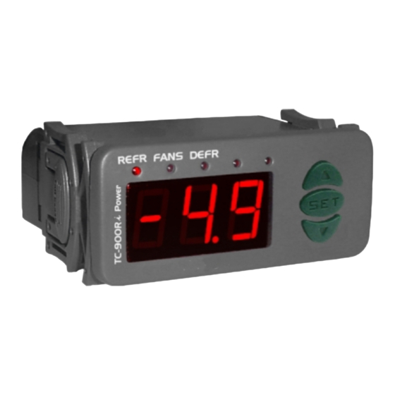
1. DESCRIPTION
TC-900Ri is a control for low temperature ventilated units which automates defrosting processes,
providing great energy saving.
It has two sensors, one for environment temperature and other that, mounted to the evaporator,
commands the end defrost process and puts the fans back to work.
Product in agreement with CE (European Community) and UL Inc. (USAand Canada).
2. APPLICATION
• Counters
• Refrigerating balconies
3. TECHNICAL SPECIFICATIONS
- Power supply:
TC-900Ri - 115/230 Vac ±10% (50/60 Hz)
TC-900RiL - 12/24 Vac/dc
- Control temperature:
-50 to 75° C
- Operating temperature:
0 to 50°C
- Operating humidity:
10 to 90% RH (without condensation)
- Resolution:
0.1°C from -10 to 75°C and 1°C outside this range
- Load current (outputs):
REFR: 5(3)A/ 250Vac 1/8HP (compressor, solenoid valve or contactor)
FANS: 5(3)A/ 250Vac 1/8HP (evaporator fans)
DEFR: 5(3)A/ 250Vac (defrost - resistance or hot gas)
- Dimensions:
71 x 28 x 71mm
- Sensors:
S1: ambient sensor (black cable)
S2: evaporator sensor (gray cable)
CLASSIFICATION ACCORDING TO IEC60730-2-9 STANDARD:
- Temperature limit of the installation surface:
- Type of construction:
Built-in electronic controller
- Automatic action:
Type 1
- Control of pollution:
Level 2
- Impulse voltage:
1,5kV
- Temperature for the test of sphere pressure:
- Insulation:
Class II
4. CONFIGURATIONS
4.1 - Control temperature adjust (SETPOINT):
- Press
for 2 seconds until appears
SET
temperature will appear.
- Use
and
to change the value and then press
4.2 - Parameters table
Fun
Description
F01
Access code:123 (one hundred and twenty-three)
F02
Control differential (hysteresis)
F03
Offset indication for ambient sensor
F04
Minimum setpoint allowed to the end user
F05
Maximum setpoint allowed to the end user
F06
Delay when the instrument is powered on
F07
Act point of high ambient temperature alert
F08
Refrigeration time (interval between defrosts)
F09
Compressor delay after on (on - off)
F10
Compressor delay after off (off - on)
F11
Compressor status with detached ambient sensor (S1)
F12
Defrost when the instrument is powered on
F13
Evaporator temperature (S2) for end defrost
F14
Maximum duration of defrost (for security)
F15
Fan turned on during defrost
F16
Defrost type
F17
Locked temperature indication (S1) during defrost
F18
Draining time (dripping of defrost water)
F19
Evaporator temperature (S2) for fan return after draining
F20
Maximum time of fan return after draining (fan-delay)
F21
Fan on with compressor off (refrigeration)
F22
Fan stopped for high temperature in the evaporator
TC-900Ri
DIGITAL CONTROLLER FOR
REFRIGERATION AND DEFROST
50°C
75°C and 125°C
, and release it after that. The adjusted operation
to record it.
SET
Min
Max
-
-
20.0
0.1
-20
20.0
-50
75.0
-50
75.0
0
30
-50
75.0
1
999
0
999
0
999
0 - off
1 - on.
0 - no
1 - yes
-50
75.0
0=disable
90
0 - no
1 - yes
0 - electric
1 - hot gas
0 - no
1 - yes
0
30
-50
75.0
0
30
0 - no
1 - yes
-50
75.0
Ver. 10
4.3 - Parameters description
F01 - Access code (123)
To change the parameters it is necessary to use the access code.It is not necessary to use the access
code to visualize the adjusted parameters.
F02 - Control differential (hysteresis)
It is the difference of temperature (hysteresis) between to turn OFF and turn ON the refrigeration output.
Example: To control the temperature in 4.0°C with differential of 1.0°C. Soon, the refrigeration will be
turned off in 4.0°C and turned on again in 5.0°C (4.0 + 1.0)
F03 - Offset indication for ambient sensor
It allows to compensate eventual shunting lines in the reading of ambient temperature (S1) proceeding
from the exchange of the sensor or cable length alteration.
F04 - Minimum setpoint allowed to the end user
F05 - Maximum setpoint allowed to the end user
Electronic limits whose purpose is prevent that too high or too low setpoint temperatures are regulated.
F06 - Delay when the instrument is powered on
When the instrument is powered on, its control is kept disabled during a time, delaying the start of
process. During this time, it works only as temperature indicator. It serves to prevent demand of electric
energy peaks, in case of lack or return of the same and when exists a lot of equipment connected on the
same net. For this, just adjust different times for each equipment. This delay may be of compressor or
defrost (when exist defrost on turn on).
F07 - Act point of high ambient temperature alert
If the ambient temperature (sensor S1) reaches this point during refrigeration, this will be signaled
visually through the indication blinking on display.
F08 - Refrigeration time (interval between defrosts)
It is the time which compressor will turn on and turn off only for ambient temperature and starts to be
counted when the fan is turned on , after fan-delay stage (fan return after draining).
F09 - Compressor delay after on (on-off)
It is the minimum time that compressor will keep on, it means, space of time between the last drive and
the next stop. It serves to prevent high voltage events in the electric network.
F10 - Compressor delay after off (off-on)
It is the minimum time that compressor will keep off, it means, space of time between the last stop and
the next drive. It serves to alliviate the discharge pressure and to increase the time of useful life of the
compressor.
F11 - Compressor status with detached ambient sensor (S1)
If the ambient sensor (S1) will be danified or outside the specified range, the compressor assumes the
configured status in this function.
Example: For counters of fruits, it is better to keep the compressor off. In counters of meat it is better to
keep the compressor on.
F12 - Defrost when the instrument is powered on
It makes possible the accomplishment of a defrost at the moment that controller is energized, for
example, in the return of electrical energy (in case of energy lack)
Unid
F13 - Evaporator temperature (S2) for end defrost
If the temperature in the evaporator (sensor S2) reaches the adjusted value, the end of defrost will be for
-
temperature. With this, the defrost process is optimized.
º C
º C
F14 - Maximum duration of defrost (for security)
This function serves to adjust the maximum value of time for defrost. If evaporator temperature does not
º C
reach the configured value in F13 in this period a point will blink in the right down side of display
º C
indicating that end of defrost ocurred for time and not for temperature.
min.
The end of defrost by time (which is not desired) can happen on the following situations:
-Adjusted temperature
º C
- Maximum time of defrost
min.
- Detached sensor or without contact with evaporator
sec.
F15 - Fan turned on during defrost
sec.
It makes possible the fan functioning during defrost.
-
Example:
Natural defrost or by resistances installed outside the evaporator.
-
F16 - Defrost type
º C
"0" = Electrical defrost (resistances), where the defrost output is active.
min.
"1" = Defrost by hot gas, where compressor and defrost outputs are actives.
-
F17 - Locked temperature indication (S1) during defrost
-
This function prevents that ambient temperature elevation during defrost be visualized, keeping the last
-
indication before defrost. The indication is released again in the initial of refrigeration cycle, after fan-
min.
delay.
º C
F18 - Draining time (dripping of defrost water)
min.
Necessary time for dripping, it means, for draining the last water drops of evaporator. All the outputs are
-
kept off. If this stage will not be desired, adjust this time for "zero".
º C
(F13)
too high
(F14)
too short
UL-Underwriters Laboratories
Advertisement

Related Manuals for Full Gauge TC-900Ri


Summary of Contents for Full Gauge TC-900Ri
- Page 1 Ver. 10 1. DESCRIPTION 4.3 - Parameters description TC-900Ri is a control for low temperature ventilated units which automates defrosting processes, F01 - Access code (123) providing great energy saving. To change the parameters it is necessary to use the access code.It is not necessary to use the access It has two sensors, one for environment temperature and other that, mounted to the evaporator, code to visualize the adjusted parameters.
- Page 2 : Defrost (heating) DEFR In normal operation, TC-900Ri indicates the ambient temperature (sensor S1) F20 - Maximum time of fan return after draining (fan-delay) The indication stays blinking when the ambient temperature (S1) reaches the adjusted value in F07.
Need help?
Do you have a question about the TC-900Ri and is the answer not in the manual?
Questions and answers