
Related Manuals for Transas NAVI-SAILOR 4100 ECDIS

Summary of Contents for Transas NAVI-SAILOR 4100 ECDIS
- Page 1 NAVI-SAILOR 4000/4100 ECDIS (VERSION 2.00.009) INSTALLATION GUIDE © Transas Ltd. March, 2009...
- Page 2 © 2009 Transas Ltd. All rights reserved. The information contained herein is proprietary to Transas Ltd. and shall not be duplicated in whole or in part. The technical details contained in this manual are the best that are available at the date of issue but are subject to change without notice.
-
Page 3: Table Of Contents
Operational System Requirements............11 Workstations Installation ..................11 Dongle Installation ................... 12 RS6 Computer ..................12 Transas ES6 Dedicated Keyboard with Trackball Installation ....12 Radar Integrator Board RIB6 ..............15 Uninterruptible Power Supply Unit UPS6 ..........23 Data Collector Unit DCU6 ................36 Power Connection.................. -
Page 4: Table Of Contents
Integrating Equipment ................133 NS 4000 Hardware Components..............133 RS6 Dedicated Computer ..............133 Uninterruptible Power Supply Unit UPS6..........136 Transas ES6 Dedicated Keyboard with Trackball......... 146 Transas Monitors................... 150 Radar Integrator Board RIB6..............160 Data Collector Unit DCU6 ..............163 WAGO I/O Modules................ -
Page 5: Preamble
PREAMBLE Copyright Transas Ltd., 2009... -
Page 7: Warnings And Cautions
Warnings and Cautions WARNINGS AND CAUTIONS Service engineers intend this document for use only, providing installation or service for Transas Ltd. navigation systems, and holding Transas Ltd. Certificates for aforementioned works. ARNING Lethal Voltage Hazard! Inside the equipment and in the cables lethal voltage hazard is present. When access covers are removed, lethal voltages may be exposed. - Page 8 • Replace whole or part of the system or components of the system with parts not specified, approved or certified by Transas or its sub manufacturers, without prior Transas written approval; • Expose the system to violent movements, excessive vibration or any situation where physical damage results;...
-
Page 9: How To Use This Manual
Navi-Sailor 4000/4100 ECDIS (v. 2.00.009). Functional Description. Navi-Sailor 4000/4100 ECDIS (v. 2.00.009). Additional Functions. Navi-Sailor 4000/4100 ECDIS (v. 2.00.009). Quick Reference. Navi-Sailor 4000/4100 ECDIS (v. 2.00.009). Installation Guide. Navi-Sailor 4000/4100 ECDIS (v. 2.00.009). Utilities. Navi-Sailor 4100 ECDIS (v. 2.00.009). Special Functions. Preamble... -
Page 10: Abbreviations In Use
Abbreviations in Use ABBREVIATIONS IN USE • AIS – Automated Identification System; • ARPA – Automatic Radar Plotting Aids; • COG – Course Over Ground; • CPA – Closest Point of Approach; • ECDIS – Electronic Chart Display Information System; •... -
Page 11: Chapter 1. Hardware Installation
CHAPTER 1 Hardware Installation Copyright Transas Ltd., 2009... -
Page 13: Ns 4000 Mfd Hardware And Software Requirements
Transas Monitors Chapter 3 Monitors (see paragraph of the ): Jakob Hatteland LCD Maritime Multi Displays (MMD); • Transas Dedicated Keyboards Chapter 3 Keyboards (see paragraph of the ES6/ES3/ES4 Dedicated Keyboards with Trackballs; • Uninterruptible Power Uninterruptible Power Supply Unit (see paragraph... -
Page 14: Dongle Installation
Layout of RS6 Computer connectors for Workstation is described in drawings Annex G “RS6 Computer. Connectors layout” enclosed in of this document. Transas ES6 Dedicated Keyboard with Trackball Installation Chapter 3 Specification of ES6 keyboard with trackball is presented in of this document. - Page 15 Workstations Installation ES6 Keyboard Connections Termination resistor is selectable by jumper. Both ends of the CAN network must be terminated with 120 ohm resistor. Node number is selectable 0–7 by jumpers (Configuration switch). Node number 0 is considered master node, and must be selected for the keyboard connected to PC by PS/2 or USB.
- Page 16 Workstations Installation Pointer data from CAN-bus and PS/2 device port will be transferred to USB port if node number 0 is set and no PC is connected to PS/2 mouse port. Keyboard data from CAN-bus and keyboard matrix will be transferred to USB port if node number 0 is set and no PC is connected to PS/2 keyboard port.
-
Page 17: Radar Integrator Board Rib6
Workstations Installation Fig. 5. ES6 Trackball. View of CAN, USB connectors and DIP-Switch Radar Integrator Board RIB6 Chapter 3 Specification of RIB6 is presented in of this document. TTENTION Check that technical characteristics of the connected equipment match characteristics Chapter 3 Hardware of the RIB6 Input/Output signals specified in , section... - Page 18 Workstations Installation • Ethernet port 2: – Use connector X5 (IP: 10.8.2.209, Netmask: 255.255.255.0, Gateway: 10.8.2.240); – This port must be used for firmware upgrades. (It is possible to use Port 1, but a few extra commands are needed); – This port can be used after Linux has booted. It will send out video data and can receive a TCP connection on port 4172 (Max 1 connection globally for RIB6).
- Page 19 Workstations Installation • RS 422 control signal: connect to X10; Fig. 6. RIB6. Layout drawing Signal Input Resistor Selector General Recommendation High resistor (1,2 kOhm) for Video and Trigger pulse is used in case of original transceiver signal distributing between Radar Display and RIB6. Low resistor (50 Ohm) for Video and Trigger pulse is used in case of direct transceiver signal connection to RIB6.
- Page 20 Workstations Installation Type of Radar Signal switch Input Atlas 8600 Video 1,2 kOhm Trigger Pulse 1,2 kOhm Bearing Pulse 1,2 kOhm Heading Pulse 1,2 kOhm Nucleus 6000 Video 1,2 kOhm Trigger Pulse 1,2 kOhm Bearing Pulse 1,2 kOhm Heading Pulse 1,2 kOhm Atlas 9600 Video...
- Page 21 Workstations Installation Checking and Settings RIB6 IP Addresses Checking RIB IP Addresses In the event of absence of the connection between PC and RIB6 check values RIB6 IP addresses. For this connect RS232 port of PC to RS232 service COM of RIB6. 1.
- Page 22 Workstations Installation 4. Restart RIB6 by means of small button Reset on RIB6 panel: 5. When the words “Hit any key to stop autoboot” appear, press any key. If the loading continues, perform the restart by using the Reset button. NAVI-SAILOR 4000/4100 ECDIS (v.
- Page 23 Workstations Installation 6. For printing configuration type “printenv” and press <Enter> button: 7. Check IP and Netmask values for LAN1 and LAN2 in correspondence to values given below: For the first type RIB6 values must be following: – Lan1ip Address: 10.8.1.209; –...
- Page 24 Workstations Installation Setting RIB6 IP Addresses 1. Set the IP addresses by using the following commands (press <Enter> button after entering each command): – Setenv lan1ip <value>; – Setenv lan1mask <value>; – Setenv lan2ip <value>; – Setenv lan2mask <value>; – Saveenv. 2.
-
Page 25: Uninterruptible Power Supply Unit Ups6
Workstations Installation Uninterruptible Power Supply Unit UPS6 UPS6 installation consists of installation following units: • EMC Filter ME-MAX/NEF/QUINT20A; • Primary-Switched Power Supply Unit QUINT-PS/1AC/24DC/20; • Uninterruptible Power Supply Unit for Universal Use QUINT-DC-UPS/24DC/20; • Battery Module 24 V DC, 3.4 Ah QUINT-BAT/24DC/3.4AH (7.2 or 12 AH). Fig. - Page 26 Workstations Installation ARNING The device contains dangerous live elements and high levels of stored energy. Never carry out work when the power is turned. The housing temperature can reach high values depending on the ambient temperature and the load of the device. In order to guarantee sufficient convection, we recommend observing the following minimum distance to other modules: 5 cm in the vertical direction and 0.5 cm in the horizontal direction.
- Page 27 Workstations Installation • Slim-style installation: Fig. 12. View of slim-style position – Assembly. Position the module with the DIN rail guide on the upper edge of the DIN rail, and snap it in with a downward motion. – Removal. Pull the snap lever open with the aid of a screwdriver and slide the module out at the lower edge of the DIN rail.
- Page 28 Workstations Installation The 100 ... 240 V AC connection is established using the L, N and PE screw connections. The device can be connected to 1-phase AC networks or to two of the phase conductors of three-phase systems (TN, TT or iT systems in acc. with VDE 0100-300/IEC 60364-3) with nominal voltages of 100 V AC ...
- Page 29 Workstations Installation • Output: Fig. 16. View of Output – Connecting the Output. The connection is established using screw connections on the screw connection of the DC output: 24 V DC: “+” and “-”; DC OK switching output active: “DC OK” and “-”; DC OK output floating: “13”...
- Page 30 Workstations Installation – Floating contact. The floating signal contact opens and signalizes a drop in the output voltage as set of more than 10%. Signals and ohmic loads of up to 30 V and currents of up to 1 A can be connected. For heavily inductive loads such as a relay, a suitable protection circuit (e.g.
- Page 31 Workstations Installation Installation of the Uninterruptible Power Supply Unit for Universal Use QUINT-DC-UPS/24DC/20 Fig. 20. Structure Table 6. Structure Comments Input voltage 24 V DC unbuffered (internal fuse 25 AT) Output voltage 24 V DC buffered (the device is idling-proof and short-circuit-proof) 24 V battery module connection Floating PDT (11,12,13): Alarm Floating PDT (21,22,23): Battery Mode...
- Page 32 Workstations Installation • Narrow Mounting Position. The device is supplied ex works for a narrow mounting position. Fig. 21. Narrow mounting position – Assembly. Place the module with the DIN rail guide way on the top edge of the DIN rail and then snap it downwards.
- Page 33 Workstations Installation For reliable and safe-to-touch connections, strip the cable ends according to the table. Table 7. Connecting cables Solid [mm²] Stranded [mm²] Torque [Nm] Input 0,5–16 0,5–10 20–6 1,2–1,5 Output 0,5–16 0,5–10 20–6 1,2–1,5 Battery 0,5–16 0,5–10 20–6 1,2–1,5 Signal 0,2–4 0,2–2,5...
- Page 34 Workstations Installation The following battery modules are recommended: – QUINT-BAT/24DC/3,4AH (Order No. 2866349); – QUINT-BAT/24DC/7,2AH (Order No. 2866352); – QUINT-BAT/24DC/12AH (Order No. 2866365). Following successful installation, the capacity of the connected battery module must be selected using the “Battery module selection” rotary switch 14. Note: The fuse on the battery module must be removed when installing or replacing the battery module.
- Page 35 Workstations Installation Setting Options on the Device • Buffer Time Setting. Buffer mode can be exited after a predefined time has elapsed or by external shutdown. If the device is to be shut down after a specific time has elapsed, the time can be set via the selector switch 13 on the front of the device.
- Page 36 Workstations Installation Table 8. Status Indicators Key/Indicators Green Power IN Yellow Bat. Red Alarm Mode/Charge Supply voltage OK, battery module Flashing charging Supply voltage OK, battery module charged (normal operation) Buffer mode Battery module flat • Battery module quality test negative •...
- Page 37 Workstations Installation Installation of the Battery Modules QUINT-BAT/24DC/3.4AH, QUINT-BAT/24DC/7.2AH, QUINT-BAT/24DC/12AH QUINT-BAT/24DC are maintenance-free lead gel rechargeable batteries for use with QUINT-DC-UPS 20A/40A. Fig. 27. View of Battery modules Safety and Warning Notes In order to guarantee safe operation of the device, please read these instructions thoroughly! The operating instructions for the particular QUINT-DCUPS must also be observed.
-
Page 38: Data Collector Unit Dcu6
Workstations Installation Installation In conjunction with adapter QUINT-ADAPTER/4, it is possible to snap the rechargeable battery module onto all 35 mm DIN rails in acc. with EN 60 715, or “keyhole” fixing eyelets can be used for rear wall mounting (drilling diagram on reverse). - Page 39 Workstations Installation DCU6 interfaces and cables fixing are shown in the figures below. DCU6 ports number 1–14 are RS 422 bi-directional channels. DCU6 ports number 15–16 are RS 422 bi-directional channels by default and may be configured by jumpers X16 and X17 accordingly as follows: •...
- Page 40 Workstations Installation Checking and Settings DCU IP Addresses Checking DCU IP Addresses In the event of absence of the connection between PC and DCU check values DCU IP addresses. For this connect RS232 port of PC to RS232 COM1 of DCU. 1.
- Page 41 Workstations Installation 4. This screen appears. Otherwise restart DCU by means of small buttons on DCU panel: Press <Escape> button. 5. For printing configuration type “1” and press <Enter> button: Chapter 1. Hardware Installation...
- Page 42 Workstations Installation 6. Check IP, Netmask, Gateway values for LAN1 in correspondence to values given below. If necessary change them by means of “Set IP Address” option in “DCU Main Menu”: 7. For the first type DCU values must be following: –...
- Page 43 Workstations Installation 10. For the first type DCU values must be following: – IP2 Address: 10.8.2.200; – Subnet Mask: value 255.255.255.0; – Default Gateway: 10.8.2.240. 11. For the second type DCU values must be following: – IP2 Address: value 10.8.2.201; –...
-
Page 44: Power Connection
Workstations Installation Power Connection Workstation requires 24 VDC. This power must be provided from 24 VDC ship’s distribution board or from optional UPS6 connected with 110/220 VAC ship’s distribution board with Main/Emergency Automatic Switch. For details, see “NS 4000/4100 ECDIS WS. - Page 45 Workstations Installation WAGO I/O Set of Modules used in NS 4000 MFD System for Conning includes the following parts: • MODBUS Coupler/Controller: the module is intended for communication of the set of WAGO I/O Modules with the Working Station via RS-232 protocol. Baud rate value recommended for use in NS 4000 MFD is 9600.
-
Page 46: Network
Network The following sequence of modules must be observed in the course of assembling: • MODBUS Module; • Digital/Analog Input Modules; • Relay Output Modules; • End Module. Cabling of the WAGO I/O Modules The following requirements must be taken into consideration prior to cabling of the WAGO I/O Modules within the NS 4000 MFD System: •... -
Page 47: Chapter 2. System Settings
CHAPTER 2 System Settings Copyright Transas Ltd., 2009... -
Page 49: Software Installation
Software Installation SOFTWARE INSTALLATION Pre-installation C:\MFD On a disk create folder Insert CD with product to the CD-drive. C:\MFD Copy all files from this folder to and close this folder. Install SPOS-6 software from Transas MNS CD. Chapter 2. System Settings... -
Page 50: Installation Of Ns 4000
Software Installation Installation of NS 4000 At each workstation, perform the following procedure. C:\MNS file in the folder Press “Next >” button. A window containing the licensing agreement text will be displayed: Press “Yes” button. The copyright information window will be displayed: Press “Next >”... - Page 51 Software Installation At this installation stage, it is necessary to make sure that the computer parameters and pre-installed software comply with specified requirements. If any critical non-compliance is identified, the installation will not be continued: Press “Next >” button. A window containing system information will be displayed. Press “Next >”...
- Page 52 Software Installation The license information will be displayed: Press “Next >” button. Select “Custom”. NAVI-SAILOR 4000/4100 ECDIS (v. 2.00.009). Installation Guide...
- Page 53 ARNING It’s strictly recommended to install “Chart Assistant” utility on the all WS. Select component “Transas Integrator” and set option “This feature will be installed on local hard drive”. Keep feature “Integrator Activation” not available, it will be activated later: Press “Next >”...
-
Page 54: Installation Of Ns 4100
Software Installation In displayed window, press “Finish” button. Installation of NS 4100 At each workstation, perform the following procedure. file in the folder Press “Next >” button. A window containing the licensing agreement text will be displayed: NAVI-SAILOR 4000/4100 ECDIS (v. 2.00.009). Installation Guide... - Page 55 Software Installation Press “Yes” button. The copyright information window will be displayed: Press “Next >” button. At this installation stage, it is necessary to make sure that the computer parameters and pre-installed software comply with specified requirements. If any critical non-compliance is identified, the installation will not be continued: Press “Next >”...
- Page 56 Software Installation Press “Next >” button. Specify the path to the product license ( by default) in displayed window: Press “Next >” button. The license information will be displayed: Press “Next >” button. Select components to be installed by the Setup Wizard (on each WS as per the licensed NS 4100 configuration).
- Page 57 Software Installation Select component “Transas Integrator” and set option “This feature will be installed on local hard drive”: Keep feature “Integrator Activation” not available, it will be activated later: Press “Next >” button. Select ECDIS and press “Next >” button.
- Page 58 Software Installation The program will perform the product installation. In displayed window, press “Finish” button. NAVI-SAILOR 4000/4100 ECDIS (v. 2.00.009). Installation Guide...
-
Page 59: Ns 4000 Configuration
NS 4000 Configuration NS 4000 CONFIGURATION Run the System Configuration utility by selecting the appropriate item in the S menu (S TART TART ROGRAMS ULTIFUNCTIONAL ISPLAY YSTEM ONFIGURATION During the NS 4000 installation enter the password. Press the “OK” button and go on to the next installation step. If the NS 4100 is being installed, in the “Logon”... -
Page 60: General
NS 4000 Configuration General The System Configuration utility consists of 5 panels; pages divide each panel. To open the required panels, press the appropriate buttons: Panel Name Purpose Button Configuration of the entire NS 4000/4100 Workstation Configuration of each Workstations separately Sensors Sensors settings, configuration of alarms, and warnings Radar... - Page 61 NS 4000 Configuration – Adjust COM ports for operation with connected sensors. The following actions shall be done for this purpose: Select required sensor from the drop-down list in the column Sensor: Alias In the column, specify the sensor name to enable its identification for the purpose of the redundancy concept.
- Page 62 NS 4000 Configuration – Check for the relevant port of this sensor: If COM-port was selected, specify in the drop-down list the following COM port exchange parameters, defined in technical description of connected sensor: Baud rate, Bits, Parity, and Stopbits; Test To check the propriety of sensor connection, press the button Port...
- Page 63 NS 4000 Configuration All the changes in the communication channel parameters are required to be made with the data monitoring turned off. If data from some sensor is not processed by the NS 4000 but is nonetheless displayed in the monitoring window, it is necessary to turn off the processing System Configuration Utility\Sensors\Sensors of data checksum from the device in Finish testing by pressing...
- Page 64 NS 4000 Configuration 4. Switch to “DCU settings” page (if the DCU is available in the equipment set): – In DCU 1-1 group check Enabled checkbox: IP 1 input box enter “10.8.1.200” IP address; IP 2 input box enter “10.8.2.200” IP address. –...
- Page 65 NS 4000 Configuration – After the connection of the DCU press the Launch DCU Test button and in the “DCU Client Simulator” utility window select the C /DCU C menu item: ONFIG ONFIG – For the devices connected to the DCU ports, specify in the drop-down list the following COM port exchange parameters, defined in the technical description of connected sensor: Baud rate, Bits, Parity, and Stopbits;...
- Page 66 NS 4000 Configuration – To check correctness of the sensor connection in the “DCU Client Simulator” utility window select the V menu item: HOW ALL – If the settings are correct, the utility windows will display information supplied to the DCU ports: –...
- Page 67 NS 4000 Configuration – Switch to the “Sensors” page and in the line of the device connected to Test Port test the NS 4000 via the DCU, press the button in the column. The ”Port DCU monitoring” window will display information supplied via the DCU to the NS 4000: Workstation 5.
- Page 68 NS 4000 Configuration RS6 I/O ports – Check the checkbox if you intend to work with the alarms/warnings via the RS6 computer discrete ports (for the port setup see items 7 and 8). 6. Switch to “Targets Subsystem” page: NAVI-SAILOR 4000/4100 ECDIS (v. 2.00.009). Installation Guide...
- Page 69 NS 4000 Configuration – Use UAIS Model group to select the model of the transponder: AIS (IEC) Press radio button to operate with any transponder complying with IEC 61993-2; Press SAAB R4 radio button to operate with SAAB R4 transponder as an MKD.
- Page 70 NS 4000 Configuration 7. Switch to “Alarm Output Settings” page: – To transfer the alarm from the NS 4000 to the external device via NMEA NMEA Alarm. Therefore, interface (Output), check the checkbox in the column when the certain alarm is triggering off in the NS 4000, the ALR sentence with ID specified in the column Id, will be outputted;...
- Page 71 NS 4000 Configuration – In the window Dead man signal of the group Other WAGO contacts, specify the number of WAGO Module contact intended for transferring the timer reset signal to the outer Alarm Panel. Therefore, the specified contact will be closed by trackball movement with resetting the “Dead Man”...
-
Page 72: Ns 4000/4100 Settings
NS 4000 Configuration Specify the WAGO Module contact by closing/unclosing of which the specified alarm will be triggered off in NS 4000. – In the column Alarm Acknowledge In Contact, specify the outer source alarm acknowledge mode: N/C – normal closed; N/O –... - Page 73 NS 4000 Configuration Role – In column, by default set Backup role for ECDIS tasks on all WS. For RADAR task on all WS set Slave role; – Use Priority column to set the workstation priority for ECDIS tasks in accordance with the NS 4000 configuration. 2.
- Page 74 NS 4000 Configuration – In the field Watches, set the navigation watches schedule; Navigational data settings, specify the period of the navigation data – In the field processing (milliseconds) (see document N 4000/4100 ECDIS AILOR . 2.00.009). F Chapter 2 Navigation , section UNCTIONAL...
- Page 75 User Ship Contour, which is to be displayed on the ECDIS task screen when the ship size comparable scale is selected (the licensed option to be ordered in Transas). 4. Switch to “Chart collections” page: – In...
- Page 76 NS 4000 Configuration 5. Switch to “Fallback” page: – If an alarm is required to be generated by the loss of the GPS differential Diff. Mode lost mode, check the checkbox. NAVI-SAILOR 4000/4100 ECDIS (v. 2.00.009). Installation Guide...
- Page 77 NS 4000 Configuration The rest of the parameters of shifting to the reserve data sources are set by default 4000/4100 ECDIS ( . 2.00.009). and not accessible for editing (N AILOR Chapter 2 UNCTIONAL ESCRIPTION , section AVIGATIONAL ENSORS Navigational Sensors Selection Automatic Source Selection paragraph , item...
- Page 78 NS 4000 Configuration 8. Switch to “ARPA Output” page: NAVI-SAILOR 4000/4100 ECDIS (v. 2.00.009). Installation Guide...
- Page 79 NS 4000 Configuration – In the field Sensor, select the ARPA_OUTPUT where the NMEA sentences will be transmitted from NS 4000. Configuration of ARPA_OUTPUT connection to the NS 4000 ports is performed on the page “Sensors” of the panel “Sensors” (see above).
- Page 80 NS 4000 Configuration 10. Switch to “Track Control” page. This page is intended for configuration Track Control functionality. – Configuration of TCS connection to the NS 4000 ports is performed on the page “Sensors” of the panel “Sensors” (see above). If external device is not connected, the page will be blank;...
- Page 81 NS 4000 Configuration Max XTD – maximum distance from the leg of the monitored route expected to be used in Track Control mode. It is set within the range of 1.0 to 5.0 mile; Initial HDG-Track – maximum deviation of the current ship course from the monitored route leg for steering to this leg with Track Control mode ON.
- Page 82 NS 4000 Configuration Turn parameters – In the group, set the ship turning circle parameters in the conditions of the selected loading option for the “Full Ahead” main engine operating mode: End Speed (rudder 15) – steady turn speed at 15º rudder angle; End Speed (rudder 35) –...
- Page 83 NS 4000 Configuration 14. Switch to the “WAGO” page. For setting up the reception of analog and discrete Annex B parameters for the CONNING task via the WAGO modules, see Adjustment of NS 4000 ECDIS MFD Operation with WAGO section Modules 15.
-
Page 84: Workstation Settings
NS 4000 Configuration Workstation Settings Press Workstation button. The drop-down Workstation list specifies the name of the workstation which settings will be made for. TTENTION Perform individual settings for each Workstation, selecting them consecutively from the droop-down list Workstation. All data will be synchronized at all the Workstations after the settings saving. - Page 85 NS 4000 Configuration 2. Switch to “Display” page: – In Monitor Type group of “Display” page, press radio button, and in Model drop-down list, select the monitor type depending on the display size and AutoDetect WS PC configuration or check checkbox;...
- Page 86 “Keyboard” page, from drop-dawn Chapter 1 lists select the keyboard type and mode (see , section Workstation Installation Transas ES6 Dedicated Keyboard , paragraph with Trackball Installation – Check Virtual keyboard enabled checkbox for use the virtual keyboard.
- Page 87 NS 4000 Configuration 6. Switch to “Skins” page: – Check Use Skin checkbox and select the type of graphic presentation Select Skin Theme window. Chapter 2. System Settings...
- Page 88 D3D video acceleration adapter checkbox is not used in this version. 8. Switch to “Integrator” page: Integrator background – In the group select the necessary product for setting the appropriate background for the Transas Integrator. NAVI-SAILOR 4000/4100 ECDIS (v. 2.00.009). Installation Guide...
-
Page 89: Radar Settings
NS 4000 Configuration Radar Settings Radar Workstation Press button. The drop-down list specifies the name of the Workstation which settings will be made for. TTENTION Perform individual settings for each Workstation, selecting them consecutively from the droop-down list Workstation. All data will be synchronized at all the Workstations after the settings saving. - Page 90 NS 4000 Configuration 2. Switch to “Radar settings” page: There may be two configurations in setting up the radar operation: – connected to the WS is an external radar which only supplies the signals (video, trigger, heading marker and bearing marker) via RIB 6; –...
- Page 91 NS 4000 Configuration – Make settings in much the same way as for the previous radar, for the IP addresses specify the following values: IP Primary input box enter “10.8.1.210”; IP Secondary input box enter “10.8.2.210”. Demo Mode: Chapter 2. System Settings...
-
Page 92: Security Settings For Ns 4000
NS 4000 Configuration Radar mode – In drop-down list, select “Master Radar” or “External Radar”; Demo mode – Check checkbox; – In the RAF file input field of Video source settings group specify the path to the folder with files; Video source settings –... - Page 93 NS 4000 Configuration • Enter the password and the password confirmation and press the “OK” button; • Set all the users whom access is granted to. TTENTION After completion of settings of all the Workstations, press the “Apply” button to save all changes done without exiting the System Configuration utility;...
-
Page 94: Security Settings For Ns 4100
NS 4000 Configuration Security Settings for NS 4100 Press Security button. • In the Users column enter the user name for configuring access to protected functions (the name can include the following characters only: “A”–“Z”, “a”–“z”, “0”–“9”, “.”, “_”); NAVI-SAILOR 4000/4100 ECDIS (v. 2.00.009). Installation Guide... - Page 95 NS 4000 Configuration • Enter the password and the password confirmation and press the “OK” button; • Level In the column, select the required access level from the listbox. The NS 4100 system has three preset user categories and access levels: •...
-
Page 96: Spos Weather Module Adjustment
In command line, press “File”. Select “System Settings” from the fall-off list. SPOS Update folder Open the page “Folders”. In the field, specify path to the folder C:\Transas\SPOS which was created automatically ( Open the page “Communication”: NAVI-SAILOR 4000/4100 ECDIS (v. 2.00.009). Installation Guide... - Page 97 Specify the path to the folder as described C:\Transas\SPOS above ( Note: For selection the method “Via MAPI”, each installation shall be examined individually, depending on the e-mail client installed on the bridge workstation.
- Page 98 SPOS Weather Module Adjustment To make sure that SPOS settings were carried out properly, run Data Tool utility by selecting the appropriate item in the Start menu (S TART ROGRAMS ULTIFUNCTIONAL ISPLAY Open internal group SPOS: The file shall be displayed in the above mentioned group showing propriety of the SPOS program settings.
-
Page 99: Navi-Conning 4000 Adjustment
Navi-Conning 4000 Adjustment NAVI-CONNING 4000 ADJUSTMENT TTENTION The Navi-Conning 4000 program setup is made separately for each WS, which it is installed in. For the correct setup it is necessary that the ECDIS tasks be run on this WS. In the ECDIS task create a route and load it for monitoring (see N AILOR 4000/4100 ECDIS ( . - Page 100 Navi-Conning 4000 Adjustment Run the CONNING task by selecting the appropriate item in the S menu TART TART ROGRAMS ULTIFUNCTIONAL ISPLAY ONNING After the program start, the NC 4000 Screen Views will be displayed. Press Setup button. NAVI-SAILOR 4000/4100 ECDIS (v. 2.00.009). Installation Guide...
- Page 101 Navi-Conning 4000 Adjustment In the “Screen View Configuration Utility” window open the S CREEN IEWS ONFIGURATION menu. AVIGATION EATHER INDOW EMPERATURE In the right hand part of the “Screen View Configuration Utility” window select the A line from the menu and press the button. IR TEMPERATURE VALUE From the menu which will open up, select the D /NMEA_C...
- Page 102 Navi-Conning 4000 Adjustment The selected source for the parameter value will be displayed in the right hand part of the “Screen View Configuration Utility” window in the A line. IR TEMPERATURE VALUE In the right hand part of the “Screen View Configuration Utility” window select the A line from the menu and press the button.
-
Page 103: Indicator Setup Table
Navi-Conning 4000 Adjustment From the menu which will open up, select the D /NMEA_C CCESS USTOM EMPERATURE line. If connected correctly, parameters will be shown dynamically on the relevant indicators, there is not need to restart Navi-Conning 4000. Press the “Save” button in the “Screen View Configuration Utility” window. ARNING For each indicator both characteristics V and V... - Page 104 Navi-Conning 4000 Adjustment Indicator Window Screen Path Views Weather/Temperature Humidity Navigation CREEN IEWS ONFIGURATION SV/W AVIGATION EATHER INDOW EMPERATURE NavData CREEN IEWS ONFIGURATION SV/W EATHER INDOW EMPERATURE Bow Thruster Ship Contour Docking CREEN IEWS ONFIGURATION SV/S OCKING INDOW Navigation CREEN IEWS ONFIGURATION SV/S...
-
Page 105: Charts Installation And Chart Assistant Adjustment
Charts Installation and Chart Assistant Adjustment Indicator Window Screen Path Views Engine STBD RPM Docking CREEN IEWS ONFIGURATION SV/E (see the next Item) OCKING NGINE ELEGRAPH INDOW Navigation CREEN IEWS ONFIGURATION SV/E AVIGATION NGINE ELEGRAPH INDOW Chart CREEN IEWS ONFIGURATION SV/E HART NGINE... - Page 106 Charts Installation and Chart Assistant Adjustment If necessary, press “Browse” button and specify the path to the directory, which contains the chart collection: Press “OK” button in the search window. Chart Assistant will scan the external storage, will automatically identify the chart format and type of data it contains, and will produce a list of available actions: Install TX97 charts checkbox is checked by default, in this case all charts, contained...
-
Page 107: Chart Assistant Adjustment
Charts Installation and Chart Assistant Adjustment Synchronize charts To synchronize the collection at all the workstations, press the collection button. Chart Assistant Adjustment Use the appropriate tab in the top left corner of the screen to switch to “Ship Collection” or “Catalogue”... - Page 108 No special subject or text is necessary. Then delete the file from the memory stick to prevent mixing up with other orders (files which will be saved by CA in the future). When you receive an e-mail from chartservice@transas.com, save attachment(s) CA_Inbox (these will be files) to memory stick in the folder.
- Page 109 Charts Installation and Chart Assistant Adjustment On this page, all the checkboxes are checked by default. Uncheck the relevant checkboxes for performing the following operations when handling S-57 format charts: • Confirm delete – to delete charts without additional warning; •...
-
Page 110: Settings In Autopilot
Settings in Autopilot SETTINGS IN AUTOPILOT Raytheon Heading Control System NP 2025 (NP 2025 Plus) To provide compliance to Track control standard there are should be done following settings: HW Settings • Sensors connection as per service manual; • NS serial data connection (“Autopilot” port) as described below: Software Settings Service part –... -
Page 111: Navis Heading Control System Ap 3000
Settings in Autopilot Other data is ship’s type depending and/or ship’s model tuning characteristics. User part – Ship and environment conditions. Parameter Y/R/C – correct settings shall be provided before track control settings. For the different type of vessel should be used different values, as a default next settings can be applied, note that this parameters can be changed depend on environment. - Page 112 Settings in Autopilot Software Settings Service part: • “INSTALLATION” main menu – (provided by service engineer only); • “DOCKTRIAL” menu: – TrackMode: ExtHTC; – ECDIS presents: Yes. • “INTERFACE” menu: – * IN (submenu): COMP1: GYRO1; COMP2: GYRO2 (if available); LOG: LOG;...
-
Page 113: Procedure Of Tcs Control Setup Algorithms
1. Adjust “Track control” section in System Configuration utility as per settings specified for the given ship type. 2. Open files in stored in C:\Program Files\Common Files\Transas Shared\Navigation\NSS directory. 3. Change the settings as required by using the fine adjustment procedure described below and save the files. - Page 114 Procedure of TCS Control Setup Algorithms Passing-of-Turn Settings 1. PivotX. Average shift of the ship’s pivot point forward relative to the ship’s geometric centre, in meters. If set incorrectly, the ship may tend to go inside (to correct this, it is necessary to increase PivotX) or outside (reduce the PivotX) relative to the set turn trajectory.
- Page 115 Procedure of TCS Control Setup Algorithms XTEs (Width of Range, nm) XTE_Ks (Course correction, deg) Value (example) 8 deg 0.75 1.00 Plausibility Check Adjustments 1. MaxHDGJump – threshold value of course change in degrees. As the course changes by a value larger than the setting within the period of one second, the Track Control mode will be stopped.
-
Page 116: Alarm Station Setup
Note: For Alarm Station licensed option only. Main Press “Start” button of the menu and select “Run” line. For registry edit in “Open” input window enter “regedit”. Press “OK” button. HKEY_LOCAL_MACHINE\Software\Transas\AlarmMon Open folder. folder select and press <Enter>. NAVI-SAILOR 4000/4100 ECDIS (v. 2.00.009). Installation Guide... - Page 117 Alarm Station Setup Type “on” in “Value data” line and press “OK” button. Note: Changes in the registers should be made individually on each workstation where the Alarm Station will be installed. Run AMS task by selecting the appropriate item in the S menu TART TART...
- Page 118 Alarm Station Setup List of groups From the listbox select a group of alarms which should be formed. By default, the list contains 6 groups. To add a group name to the list, enter it in Group's name input box and press the button.
- Page 119 Alarm Station Setup You can sort the alarms in the table by the name and ID by pressing on the relevant column name. Press the button to the left of the name of the alarm (warning), is replaced with On). which should be included in the group (Off If necessary, enter the name of the alarm (warning) under which it will be displayed...
-
Page 120: Activation Of Transas Integrator
Activation of Transas Integrator ACTIVATION OF TRANSAS INTEGRATOR TTENTION This procedure is performed for each WS. Activate Transas Integrator by selecting the appropriate item in the S menu TART TART ROGRAMS ULTIFUNCTIONAL ISPLAY CTIVATE NTEGRATOR Upon computer restart, the Transas Integrator window will be opened: Run all the tasks on the all the WS’s and check their correct operation. -
Page 121: Commissioning Table Creation And System Configuration Back Up
Commissioning Table Creation and System Configuration Back Up COMMISSIONING TABLE CREATION AND SYSTEM CONFIGURATION BACK UP Restart all WS. Press button for run System Configuration utility. Commissioning Table Creation Press Commissioning Table button: Chapter 2. System Settings... -
Page 122: Ns 4000 Configuration Back Up
Commissioning Table Creation and System Configuration Back Up Filename input field specify the path to Commissioning Table file C:\Transas\IBS (by default, Press “Save” button. When the Commissioning Table is created, this should be done at each WS. Also, after each change of configuration (e.g., if a new GPS is connected) the Commissioning Table should be made anew at each WS. - Page 123 Commissioning Table Creation and System Configuration Back Up Specify the path here backup the file will be stored, and press “OK” button. Press “OK” button. Press “OK” button. Note: The Navi-Conning configuration in the new product version is saved simultaneously with the NS 4000 configuration backup. Chapter 2.
-
Page 124: Ns 4000 Registry
Commissioning Table Creation and System Configuration Back Up NS 4000 Registry Press button for run First Aid utility. Switch to “Registry” page: Fill in all the lines and press the Make Registry button. NAVI-SAILOR 4000/4100 ECDIS (v. 2.00.009). Installation Guide... -
Page 125: Software Upgrade
Upgrade of Entire NS 4000 Product Perform the NS 4000 Configuration Backup procedure on one of the WS with RIB6 installed. Deactivate Transas Integrator on each WS. To do this, press <Ctr>+<Alt>+<Shift>+<F8> keys. Enter password and press “OK” button, PC will be restarted. - Page 126 Software Upgrade Select “Multifunctional Display”. Press “Remove” button. Press “Yes” button. After program deinstallation, restart PC. Software Installation Install new version of NS 4000 (see section , paragraph Installation of NS 4000 Run First Aid utility by selecting the appropriate item in the S menu TART TART...
- Page 127 Software Upgrade On “Product” page in Name drop-down list, press button and select product (if necessary). Press Navigation program would not start or has hung up at the start button: Press Restore button. Press “Yes” button. Chapter 2. System Settings...
- Page 128 Software Upgrade Specify the path to back up file and press “Open”. The configuration will be restored. Press “OK” button and close First Aid utility. Activation of Transas Integrator Activate Transas Integrator (see section NAVI-SAILOR 4000/4100 ECDIS (v. 2.00.009). Installation Guide...
-
Page 129: Upgrade Navi-Conning 4000
Software Upgrade Upgrade Navi-Conning 4000 To start Data Tool utility press the button. After the utility is run the screen displays a control window: Select from the drop-down list the Navi-Conning 4000 application. Chapter 2. System Settings... - Page 130 Software Upgrade Select from the Internal drop-down list the Conning group. External group press call button to the right of the window and specify the path to the folder with new configuration file Copy Press button in the utility toolbar. NAVI-SAILOR 4000/4100 ECDIS (v.
- Page 131 Software Upgrade Exit from the Data Tool utility. Restart Navi-Conning 4000. Chapter 2. System Settings...
-
Page 133: Chapter 3. Technical Specification
CHAPTER 3 Technical Specification Copyright Transas Ltd., 2009... - Page 135 General GENERAL NS 4000 Physical Layout The purpose of the NS 4000 is to provide maximum to simplify and facilitate the officer in charge of the navigational watch (OOW), planning, monitoring, and control the voyage of a vessel. Sensors and control systems are not the part of NS 4000 but just connected equipment with none or minimal modification in order to ensure proper integration.
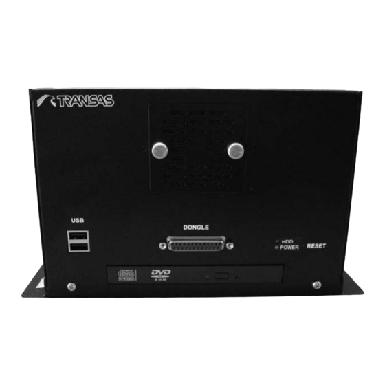
- Page 136 NS 4000 Hardware Components Fig. 35. View of RS6 front side Fig. 36. View of RS6 rear side RS6 Housing • RS6 mountable chassis (shown on figures above); • Cooling unit: Cooltek 80 x 80 x 25 mm 16 CFM fan; •...
- Page 137 NS 4000 Hardware Components ICES200 Features The ICES 200 is a Type 2 COM Express Module featuring Intel 945GME and ® ICH7M chipset, switch supports Intel Core 2 Duo and Intel Core 2 Duo LV ® ® processors with 533/667 MHz FSB and one DDR2 memory socket up to 2GB. The ICES 200 integrated with Intel Graphics Media Accelerator (GMA950).
- Page 138 NS 4000 Hardware Components Uninterruptible Power Supply Unit UPS6 General This Uninterruptible Power Supply (UPS) is designed to prevent blackouts, brownouts, sags and surges from reaching computer with NS 4000. This UPS also filters out small utility line fluctuations and isolates equipment from large disturbances by internally disconnecting from the utility line, while supplying power from its internal batteries until the utility line returns to safe level.
- Page 139 NS 4000 Hardware Components Technical Data • Input data: – Nominal input voltage range: 100...240 V AC; – Input voltage range: 85...264 V AC, 90...350 V DC; – Short-term input voltage: 300 V AC; – Frequency range: 45...65 Hz (0 Hz at DC input); –...
- Page 140 NS 4000 Hardware Components • Signal output DC OK floating: – Output description: relay contact, Uout > 0.9 x Un: contact closed; – Voltage: 30 V AC/DC; – Current: 1 A; – Status display: “DC OK” LED green/Uout < 0.9 x Un: LED flashing. •...
- Page 141 NS 4000 Hardware Components Dimensions Fig. 38. Power Supply Unit QUINT PS/1AC/24DC/20 dimensional drawing Fig. 39. EMC Filter dimensional drawing Chapter 3. Technical Specification...
- Page 142 NS 4000 Hardware Components Uninterruptible Power Supply Unit for Universal Use QUINT-DC-UPS/24DC/20 Description Uninterruptible Power Supply Units for Buffering Long-Term Power Interruptions: • Saves space thanks to the compact, uniform design; • Integrated diode saves money through isolation of loads; •...
- Page 143 NS 4000 Hardware Components Technical Data • Input data: – Nominal input voltage: 24 V DC; – Input voltage range: 22.5–30 V DC; – Current consumption (no load/charging/maximum): 0.1 A/2.0 A/22.0 A; – Switching threshold: U < 22 V; dynamic U –...
- Page 144 NS 4000 Hardware Components • General data: – Insulation voltage (Input/output to housing): 1 kV AC type test/1 kV AC routine test; – Mounting position: on a horizontal 35 mm (1.378 in.) DIN rail EN 60715; – Degree of protection: IP20; –...
-
Page 145: Technical Data
NS 4000 Hardware Components Technical Data Technical data of Battery modules presented in the table below: Table 13. Battery modules technical specification Technical data/Type QUINT- QUINT- QUINT- BAT/24DC/3.4AH BAT/24DC/7.2AH BAT/24DC/12AH Order No. 28 66 34 9 28 66 35 2 28 66 36 5 Nominal voltage 24 V DC... - Page 146 NS 4000 Hardware Components Dimensions Fig. 41. QUINT-BAT/24DC/3.4AH battery dimensional drawing Fig. 42. QUINT-BAT/24DC/7.2AH battery dimensional drawing NAVI-SAILOR 4000/4100 ECDIS (v. 2.00.009). Installation Guide...
- Page 147 NS 4000 Hardware Components Fig. 43. QUINT-BAT/24DC/12AH battery dimensional drawing Fig. 44. Battery modules mounting brackets dimensional drawing Chapter 3. Technical Specification...
-
Page 148: Transas Es6 Dedicated Keyboard With Trackball
NS 4000 Hardware Components Transas ES6 Dedicated Keyboard with Trackball General • ES6 keyboard with Trackball (the ES6 in what follows) is a control unit inside the Transas systems; • The ES6 consists of: – The PC compatible keyboard unit with two fields (QWERTY- and function-keys);... - Page 149 NS 4000 Hardware Components Keyboard Function Field All function keys have a tactile switch on the PCB to give a distinct “click” feeling. The tracking keys are printed with a “hiding-effect“, i.e. the key legends are normally invisible when not lit. They are lit only when the tracking function is active. Fig.
- Page 150 NS 4000 Hardware Components ES6 key/control Function Comment ALL LAYERS To turn on display of all the possible chart information layers OVERLAY To turn on/off the Overlay mode • Daylight; DAY/NT To switch successively colour palettes • Twilight; • Dusk; •...
- Page 151 The illumination intensity is controlled backlighting by using Dimmer GAIN To adjust the video signal gain level To adjust the sea clutter suppressions RAIN To adjust the rain clutter suppressions Dimensions Fig. 46. Transas ES6 dedicated keyboard dimensional drawing Chapter 3. Technical Specification...
-
Page 152: Transas Monitors
NS 4000 Hardware Components Transas Monitors Jakob Hatteland LCD Maritime Multi Displays (MMD) General As a dedicated part of systems Transas Marine Ltd uses Industrial Colour Monitors manufactured for Transas by Jakob Hatteland Display AS. The following types of monitors are used: •... - Page 153 NS 4000 Hardware Components 19" TFT Hatteland 19" TFT Hatteland 23" TFT Hatteland HD19T03 MMD JH19T14 MMD JH23T12 MMD Synchronization • Digital separate synchronization; Sync Signal • Composite synchronization; • Synchronization on green; • Interlaced and non interlaced • Auto detect VGA -> Auto detect VGA ->...
- Page 154 NS 4000 Hardware Components 19" TFT Hatteland 19" TFT Hatteland 23" TFT Hatteland HD19T03 MMD JH19T14 MMD JH23T12 MMD Available Options/Accessories COM2 1 x D-SUB 9P (female) • HD VESA 19TBR-A1 – Bracket JH MMD BR JH 23TBR T01-A1 VESA bracket for complete unit;...
- Page 155 NS 4000 Hardware Components Fig. 48. 19'' TFT Hatteland JH19T14 MMD. Bracket View Fig. 49. 19''/23” TFT Hatteland JH19T14/JH23T12 MMD. Rotary Bracket View Chapter 3. Technical Specification...
- Page 156 NS 4000 Hardware Components Fig. 50. 23'' TFT Hatteland JH23T12 MMD. Standard View Fig. 51. 23'' TFT Hatteland JH23T12 MMD. Bracket View NAVI-SAILOR 4000/4100 ECDIS (v. 2.00.009). Installation Guide...
- Page 157 NS 4000 Hardware Components Fig. 52. 19'' TFT Hatteland HD19T03 MMD. Standard View Fig. 53. 19'' TFT Hatteland HD19T03 MMD Bracket View Chapter 3. Technical Specification...
- Page 158 NS 4000 Hardware Components Fig. 54. 19'' TFT Hatteland HD19T03 MMD Console Bracket View Fig. 55. 19'' TFT Hatteland HD19T03 MMD Vesa Bracket View NAVI-SAILOR 4000/4100 ECDIS (v. 2.00.009). Installation Guide...
- Page 159 NS 4000 Hardware Components Products JH19T02 and JH23T02 Specification Table 16. Jakob Hatteland LCD Maritime Multi Displays JH19T02 and JH23T02 Characteristics 19" TFT Hatteland JH 19 T02 23" TFT Hatteland JH 23 T02 MMD E1/E2 MMD E1/E2 TECHNICAL DESCRIPTION TFT Technology 19.0 inch viewable image size 23.1 inch viewable image size Active Matrix...
- Page 160 NS 4000 Hardware Components 19" TFT Hatteland JH 19 T02 23" TFT Hatteland JH 23 T02 MMD E1/E2 MMD E1/E2 Accessories Touch screen 1 x D-SUB 9P Connector (female) Remote Control 2 x D-SUB 9P Connector (female) User Controls • Power On/Off (push button); On front bezel •...
- Page 161 NS 4000 Hardware Components Fig. 57. 19" TFT Hatteland JH 19 T02 MMD. Bracket View Fig. 58. 23" TFT Hatteland JH 23 T02 MMD. Standard View Chapter 3. Technical Specification...
- Page 162 The Radar Integrator Board (what’s follow RIB6) is designed for the reception of analog video signals from the radar and their digitizing, pre-processing and relay of the radar signal to the dual network as per network protocols for the TRANSAS navigational products.
- Page 163 NS 4000 Hardware Components Concurrently with the operation of the data reception and processing algorithm, data is transmitted and received via the RS422 serial port. Fig. 60. Radar signal processing Electrical Characteristics • Control Signal: – Electrical format: RS422. – Signal type: binary or alpha numeric (NMEA). –...
- Page 164 NS 4000 Hardware Components • Trigger: – Maximum voltage: +/- 25 V; – Input Impedance: 10KOhm, 1 KOhm, 75 Ohm, 50 Ohm (manually selectable by jumper); – Signal type: square pulse; – Singled ended and differential input (manually selectable by jumper); –...
- Page 165 Data Collecting Unit (what’s follow DCU), this device through which is realized connection of navigational data sources (such as GPS, GYRO, LOG, AIS, etc) using NMEA standard (IEC 61162) to Transas Workstations. DCU power supply is performed with the cable connected to the external 24 VDC power supply.
- Page 166 • In case if all 16 RS ports will be loaded 2400 by bi-directional data transferring with baud rate 4800 between 1200 and 38400 then no more than 9600 25 Transas Workstations could work with same 19200 DCU; 38400 • Baud rate 57600 – then no more than 57600 15 Transas Workstations could work with same DCU;...
-
Page 167: Wago I/O Modules
NS 4000 Hardware Components WAGO I/O Modules MODBUS Fieldbus Coupler (750-314) This buscoupler allows connection of the WAGO-I/O-SYSTEM as a slave to the MODBUS fieldbus. The buscoupler is capable of supporting all bus modules. The bus coupler automatically configures, creating a local process image which may include analog, digital or specialty modules. - Page 168 NS 4000 Hardware Components Table 19. WAGO MODBUS specification Description MODBUS/ RS 232/ 150–19200 Bd 750-314 General specifications Dimensions from upper edge 51 x 65 x 100 of DIN 35 rail (mm) W x H x L Weight 200 g Wire connection CAGE CLAMP 0.08–2.5 mm ;...
- Page 169 NS 4000 Hardware Components Table 20. 4-Channel Digital Input modules DC 24 V specification Description 4DI 24V DC 0.2 ms 750-403 General specifications Dimensions from upper edge 12 x 64 x 100 of DIN 35 rail (mm) W x H x L Weight 50 g Wire connection CAGE CLAMP...
- Page 170 NS 4000 Hardware Components Technical data No. of inputs Voltage supply Via system voltage DC /DC Current consumption typ. (internal) 70 mA Common mode voltage (max.) 35 V Signal current 4 mA - 20 mA (750-454) Input resistance < 220 Ohm at 20 mA Resolution 12 bits Conversion time (typ.)
- Page 171 NS 4000 Hardware Components Conversion time (typ.) 80 ms Measuring error (25 ºC) <±0.1% of the full scale value Temperature coefficient <±0.01%/K of the full scale value Isolation 500V system/supply Bit width 2 x 16 bits data and 2 x 8 bits control/status (option) Input filter 50 Hz Noise rejection at sampling frequency...
- Page 172 NS 4000 Hardware Components 2-Channel Relay Output Module AC 230 V, DC 30 V The connected load is switched via the digital output (relay contacts) from the control system. The internal system voltage is used to trigger the relay. The NO contacts are electrically isolated.
-
Page 173: Moxa Switch Type Approved Eds-305/308/316 Series
NS 4000 Hardware Components End Module (750–600) After the fieldbus node is assembled with the correct buscoupler and selected I/O modules, the end module is snapped onto the assembly. It completes the internal data circuit and ensures correct data flow. One is required for each buscoupler. Fig. - Page 174 NS 4000 Hardware Components Specification Technology • Standards: IEEE802.3, 802.3u, 802.3x; • Processing type: Store and Forward; • Flow control: IEEE802.3x flow control, back pressure flow control. Interface • RJ45 ports: 10/100BaseT(X) auto negotiation speed, F/H duplex mode, and auto MDI/MDI-X connection; •...
- Page 175 NS 4000 Hardware Components Dimensional Drawing Fig. 71. MOXA switch type approved EDS-305/308/316 series dimensional drawing Chapter 3. Technical Specification...
-
Page 177: Chapter 4. Interface Capabilities
CHAPTER 4 Interface Capabilities Copyright Transas Ltd., 2009... - Page 179 General GENERAL In order to operate adequately in conjunction with navigational sensors, the NS 4000 should receive certain data from them. This data is required to be transmitted in accordance with Standard IEC 61162-1 M ARITIME NAVIGATION AND RADIO COMMUNICATION EQUIPMENT AND SYSTEMS IGITAL INTERFACES INGLE TALKER AND MULTIPLE LISTENERS or in NMEA-0183 format.
-
Page 180: Format Of Data Exchange Used In Accordance With Iec 61162-1 Standard
Format of Data Exchange Used in Accordance with IEC 61162-1 Standard FORMAT OF DATA EXCHANGE USED IN ACCORDANCE WITH IEC 61162-1 STANDARD Input Summary Table The summary table shows the principles of operation with each navigation sensor. Sensor Data type transmitted Sentences NS 4000 channel by sensor... -
Page 181: Format Of Input Data
Format of Data Exchange Used in Accordance with IEC 61162-1 Standard Sensor Data type transmitted Sentences NS 4000 channel by sensor carrying this data which the sensor is connected to ALARM STATION Alarm state and ALARM STATION 1 acknowledgement (ALARM STATION 2…) NMEA NAVTEX NAVTEX Messages NAVTEX... - Page 182 Format of Data Exchange Used in Accordance with IEC 61162-1 Standard DBT – Depth Below Transducer Standard: IEC 61162-1, 2000. $--DBT, x.x , x.x , x.x *hh<CR><LF>. Field Name Value Comments Depth Depth value Measurement unit “f” – feet Depth Depth value Measurement unit “M”...
- Page 183 Format of Data Exchange Used in Accordance with IEC 61162-1 Standard GBS – GPS Satellite Fault Detection Standard: NMEA 0183 v.3.00, 2000. This message is used to support Receiver Autonomous Integrity Monitoring (RAIM). Given that a GNSS receiver is tracking enough satellites to perform integrity checks of the positioning quality of the position solution a message is needed to report the output of this process to other systems to advice the system user.
- Page 184 Format of Data Exchange Used in Accordance with IEC 61162-1 Standard Field Name Value Comments Horizontal dilution of precision Antenna altitude re: Not processed mean-sea-level Measurement units “M” – metres Not processed Geoidal separation Vertical difference between the Not processed WGS-84 earth ellipsoid and mean-sea-level (geoid), “-”...
- Page 185 Format of Data Exchange Used in Accordance with IEC 61162-1 Standard HDT – Heading, True Standard: IEC 61162-1, 2000 IMO Resolution A.424 and .821. $--HDT, x.x *hh<CR><LF>. Field Name Value Comments Heading (degrees) Heading type “T” – True MTW – Water Temperature Standard: IEC 61162-1, 2000.
- Page 186 Format of Data Exchange Used in Accordance with IEC 61162-1 Standard RMC – Recommended Minimum Specific GPS Data Standard: IEC 61162-1, 2000. Contains: time, date, position, course and speed data provided by a GPS receiver. $--RMC, hhmmss.ss , llll.ll , yyyyy.yy , x.x , x.x , xxxxxx...
- Page 187 Format of Data Exchange Used in Accordance with IEC 61162-1 Standard TTM – Tracked Target Message Standard: IEC 61162-1, 2007. $--TTM, xx , x.x , x.x , x.x , x.x , x.x , x.x , c--c , hhmmss.ss *hh<CR><LF>. Field Name Value Comments...
- Page 188 Format of Data Exchange Used in Accordance with IEC 61162-1 Standard Field Name Value Comments Data status “A” – reliable data Shall not be null “V” – unreliable data Stern transverse Negative to ground speed (knots) the portside Data status “A”...
-
Page 189: Output
Format of Data Exchange Used in Accordance with IEC 61162-1 Standard VWR – Relative (Apparent) Wind Speed and Angle Standard: IEC 61162-1, 2000. $--VWR, x.x , x.x , x.x , x.x *hh<CR><LF>. Field Name Value Comments Measured wind angle In degrees (from 0 to 180) relative to the vessel Left/right of the vessel “L”... -
Page 190: Format Of Output Data
Format of Data Exchange Used in Accordance with IEC 61162-1 Standard Group of transmitted data Data channel in “System Sentence transmission rate Configuration Utility” NAV DATA NMEA output Every second (ALR, ACK, DTM; GLL; HDT; ZDA; OSD; DPT) NAV DATA AUTOPILOT Every second Ownship position (GLL) - Page 191 Format of Data Exchange Used in Accordance with IEC 61162-1 Standard ALR – Set Alarm State Standard: IEC 61162-1, 2000. $--ALR, hhmmss.ss ,xxx ,c--c *hh<CR><LF>. Field Name Value Comments hhmmss.ss Time of alarm Hours, minutes, seconds (UTC) condition change Local alarm identifier Alarm number Alarm condition A = threshold exceeded,...
- Page 192 Format of Data Exchange Used in Accordance with IEC 61162-1 Standard BOD – Bearing Origin to Destination Standard: IEC 61162-1, 2007. $--BOD, x.x , x.x , c--c , c--c *hh<CR><LF>. Field Name Value Comments Bearing Degrees True Bearing Degrees Magnetic c--c Destination waypoint ID c--c...
- Page 193 Format of Data Exchange Used in Accordance with IEC 61162-1 Standard HDT – Heading, True Format of Input Data See paragraph of this section. OSD – Own Ship Data Standard: IEC 61162-1, 2007. $--OSD, x.x , x.x , x.x , x.x , x.x *hh<CR><LF>.
- Page 194 Format of Data Exchange Used in Accordance with IEC 61162-1 Standard Field Name Value Comments Destination closing knots velocity Arrival status A = Autonomous mode, Mode indicator D = Differential mode, E = Estimated (dead reckoning) mode, M = Manual input mode, S = Simulator mode, N = Data not valid RTE –...
-
Page 195: Universal Ais Transponder Interface
Universal AIS Transponder Interface WPL – Waypoint Location Format of Input Data See paragraph of this section. XTE – Cross-Track Error, Measured Standard: IEC 61162-1, 2007. $--XTE, A , x.x *hh<CR><LF. Field Name Value Comments Status A = data valid, V = LORAN –... - Page 196 Universal AIS Transponder Interface Level 3 Data processing is implemented to a full extent according to the descriptions provided below in sections: • IALA Technical Clarifications on Recommendation ITU-R M.1371 Edition 1.3 Standard Sentences • Sentences Transmitted by the ECDIS via AIS Channel in the Operation with a Transponder Summary Table Message...
- Page 197 Universal AIS Transponder Interface IALA Technical Clarifications on Recommendation ITU-R M.1371 Edition 1.3 Standard Sentences VDO – VHF Data-Link Own-Vessel Message The NS 4000 for the reception uses this sentence only. It contains information on the own ship set in the ship UAIS station. Standard: IEC 61993-2, 2001-11-09.
- Page 198 Universal AIS Transponder Interface Parameter Number Description Comments of bits Navigational 0 = Underway using engine status 1 = At anchor 2 = Not under command 3 = Restricted manoeuvrability 4 = Constrained by her draught 5= Moored 6 = Aground 7 = Engaged in Fishing 8 = Underway sailing 9 = HSC (High Speed Craft)
- Page 199 Universal AIS Transponder Interface 4 – Base Station Report (VDM) The NS 4000 for the reception uses this sentence only. Standard: ITU-R M.1371, 2000. Parameter Number Description Comments of bits Message ID Identifier for message 4 4 = UTC and position report from base station Repeat Indicator Not processed by the NS 4000...
- Page 200 Universal AIS Transponder Interface 5 – Static and Voyage Related Data (In Sentences VDO and VDM) The NS 4000 for the reception uses this sentence only. Standard: ITU-R M.1371, 2000. Parameter Number Description Comments of bits Message ID Identifier for message 5 Repeat Indicator Not processed by the NS 4000...
- Page 201 Universal AIS Transponder Interface 6 – Addressed Binary Message (In VDM) The NS 4000 for the reception uses this sentence only. Standard: ITU-R M.1371, 2000. Parameter Number Description Comments of bits Message ID Identifier for message 6 Repeat Indicator Not processed by the NS 4000 Source ID MMSI number of source station...
- Page 202 Universal AIS Transponder Interface 9 – Standard SAR Aircraft Position Report (In VDM) The NS 4000 for the reception uses this sentence only. Standard: ITU-R M.1371, 2000. Parameter Number Description Comments of bits Message ID Identifier for message 9; always 9 Repeat Indicator Not processed by the NS 4000...
- Page 203 Universal AIS Transponder Interface 12 – Addressed Safety Related Message (In VDM) The NS 4000 for the reception uses this sentence only. Standard: ITU-R M.1371, 2000. Parameter Number Description Comments of bits Message ID Identifier for Message 12; always 12 Repeat Indicator Not processed by the NS 4000...
- Page 204 Universal AIS Transponder Interface Parameter Number Description Comments of bits Position 1 = high (< 10 m; Differential Mode of accuracy e.g. DGNSS receiver). 0 = low (> 10 m; Autonomous Mode of e.g. GNSS receiver or of other Electronic Position Fixing Device);...
- Page 205 Universal AIS Transponder Interface Parameter Number Description Comments of bits Longitude Longitude in 1/10 000 min. ( 180 degrees, East = positive (as per 2´s complement), West = negative (as per 2´s complement). 181 degrees (6791AC0 hex) = not available = default) Latitude Latitude in 1/10 000 min.
- Page 206 Universal AIS Transponder Interface 21 – Aids-to-Navigation Report The NS 4000 for the reception uses this sentence only. Standard: ITU-R M.1371, 2000. Parameter Number Description Comments of bits Message ID Identifier for message 21; always 21 Repeat Indicator Not processed by the NS 4000 MMSI number Type of Aids-to-...
- Page 207 Universal AIS Transponder Interface Parameter Number Description Comments of bits Time Stamp UTC second when the report was generated by the EFPS (0–59, or 60 if time stamp is not available, which should also be the default value, or 61 if positioning system is in manual input mode, or 62 if Electronic Position Fixing System operates in estimated (dead reckoning) mode, or 63 if the position system is inoperative)
- Page 208 Universal AIS Transponder Interface Table “Type of Aids to Navigation” The nature and type of A-to-N can be indicated with 32 different codes, as shown below: Code Definition Default, Type of A-to-N not specified Reference point RACON Structure off shore, such as oil platforms, wind farms, rigs. (Note: This code should identify an obstruction that is fitted with an Aid-to-Navigation AIS station.) Spare Fixed A-to-N...
- Page 209 Universal AIS Transponder Interface Sentences Transmitted by the NS 4000 via AIS Channel in the Operation with a Transponder AIQ, ALR – Monitoring of Set Alarm State The NS 4000 in following cases transmits this sentence: • At the NS 4000 start; •...
- Page 210 Universal AIS Transponder Interface ABK – Addressed Binary and Safety Related Message This sentence is used by the NS 4000 for the reception only via AIS channel in NS 4000. The ABK-sentence is generated when a transaction, initiated by reception of an ABM, AIR, or BBM sentence, is completed or terminated.
- Page 211 Universal AIS Transponder Interface Note: Acknowledgements provided are: • 0 = message (6 or 12) successfully received by the addressed AIS unit; 1 = message (6 or 12) was broadcast, but no acknowledgement by the distant addressed AIS unit; • 2 = message could not be broadcast; •...
- Page 212 Universal AIS Transponder Interface ALR – Set Alarm State This sentence is used by the NS 4000 for the transmission and reception via AIS channel in NS 4000. Local alarm condition and status. This sentence is used to report an alarm condition on a device and its current state of acknowledgment.
- Page 213 Universal AIS Transponder Interface SSD – Ship Static Data This sentence is used by the NS 4000 for the transmission and reception via AIS channel in NS 4000. Standard: IEC 61993-2, 2001-11-09. $--SSD, c--c , c--c , xxx , xxx , xx , xx , aa...
- Page 214 Universal AIS Transponder Interface VSD – Voyage Static Data This sentence is used by the NS 4000 for the reception and transmission via AIS channel in NS 4000. Standard: IEC 61993-2, 2001-11-09. $--VSD, x.x , x.x , x.x , c--c , hhmmss.ss , xx , xx...
- Page 215 Universal AIS Transponder Interface Ships/Cargo type VSD message identifier HSC (Carrying DG, HS, or MP IMO hazard or pollutant category D) HSC (No additional information) Pilot vessel Search and rescue vessel Port tender Vessel with antipollution facilities Law enforcement vessel Medical transport (as defined in the 1949 Geneva Conventions) Ship according to Resolution No 18 (Mob –...
- Page 216 Universal AIS Transponder Interface The AIS automatically selects the position source with the highest priority available. If data availability changes, the AIS automatically switch to the position source with the highest priority available after 5 sec when switching downwards, or 30 sec when switching upwards.
-
Page 217: Navtex Sensor Data Exchange Format
NAVTEX Sensor Data Exchange Format NAVTEX SENSOR DATA EXCHANGE FORMAT NMEA Format NRX – NAVTEX Received Message The NRX sentence is used to transfer the contents of a received NAVTEX message from the NAVTEX receiver to another device. As the length of a single NAVTEX message may exceed the number of characters permitted in a single sentence, many NRX sentences may be required to transfer a single NAVTEX message. -
Page 218: Ascii Format
NAVTEX Sensor Data Exchange Format NRM – NAVTEX Receiver Mask This command is used to manipulate the configuration masks that control which messages are stored, printed, and sent to the NS 4000 port of the NAVTEX receiver. $--NRM,x ,hhhhhhhh ,hhhhhhhh *hh<CR><LF>. -
Page 219: Description Of The Ns 4000 And Rhotheta Rt-202 Rdf Interface
Description of the NS 4000 and Rhotheta RT-202 RDF Interface DESCRIPTION OF THE NS 4000 AND RHOTHETA RT-202 RDF INTERFACE The NS 4000 is processing a constant data flow supplied by Rhotheta RT-202 radio direction finder according to certain rules. No messages are transmitted from the NS 4000 to RT-202. - Page 220 Description of the NS 4000 and Rhotheta RT-202 RDF Interface – If the two above conditions are fulfilled, the NS 4000 processes field “A” containing information on the MOB object bearing. It should be noted that this is a relative bearing, whereas to be plotted in the ECDIS task or transmitted to other ships via the AIS, the bearing should be corrected to true.
- Page 221 ANNEX A Cisco PIX-501-BUN-K9 Firewall Installation and Adjustment Copyright Transas Ltd., 2009...
- Page 223 Configuring the PIX-501-BUN-K9 CONFIGURING THE PIX-501-BUN-K9 There are two ways of configuring PIX-501-BUN-K9: • Configuring using the Console Port; • Configuring using the PDM. Configuring the PIX-501-BUN-K9 Using Console Port You can access the Command Line Interface (CLI) for administering by using the console port on the PIX Firewall.
- Page 224 Configuring the PIX-501-BUN-K9 Configuring the PIX-501-BUN-K9 Using PDM Version 3.(0)2 The PIX-501-BUN-K9 contains an integrated configuration utility called Cisco PIX Device Manager (PDM). PDM is a web browser-based configuration tool designed to help you set up, configure, and monitor the PIX Firewall. PDM is preinstalled on the PIX-501-BUN-K9.
- Page 225 Configuring the PIX-501-BUN-K9 2. Click on “Local Area Connection” icon, press right mouse button and select ROPERTIES 3. Select “Internet Protocol (TCP/IP)” and press “Properties” button: 4. Switch on “Obtain an IP address automatically” and “Obtain DNS server address automatically”. Press “OK” button: Annex A.
- Page 226 Configuring the PIX-501-BUN-K9 5. Run to S . Double-click the “Internet Options” icon: TART ETTING ONTROL ANEL 6. Switch to “Connections” tab and press “LAN Settings…” button: 7. Check “Automatically detect settings” checkbox and press “OK” button: NAVI-SAILOR 4000/4100 ECDIS (v. 2.00.009). Installation Guide...
- Page 227 Configuring the PIX-501-BUN-K9 8. To access the PDM, enter the URL: https://192.168.1.1 into your browser. Note: Remember to add the “s” to “https” or the connection fails. 9. Press “OK” button: 10. Press “Yes” button: 11. Leave both the “User Name” and “Password” input windows empty. Press “OK” button and wait for loading PDM: Annex A.
- Page 228 Configuring the PIX-501-BUN-K9 12. Check “Always trust content from Cisco Systems” checkbox and press “Yes” button: NAVI-SAILOR 4000/4100 ECDIS (v. 2.00.009). Installation Guide...
- Page 229 Configuring the PIX-501-BUN-K9 13. Run to F menu and click on R ESET IREWALL TO THE ACTORY EFAULT ONFIGURATION Annex A. Cisco PIX-501-BUN-K9 Firewall Installation and Adjustment...
- Page 230 Configuring the PIX-501-BUN-K9 14. In the “Inside IP Address” field enter the value 10.8.1.100 and in “Inside Subnet Mask” field choose 255.255.255.0. Press “OK” button: 15. Press “Yes” button and wait for one minute: NAVI-SAILOR 4000/4100 ECDIS (v. 2.00.009). Installation Guide...
- Page 231 Configuring the PIX-501-BUN-K9 16. Press “OK” button and wait while PDM is loading the current configuration from Firewall: 17. Press “OK” button: 18. Run to F menu and select E Annex A. Cisco PIX-501-BUN-K9 Firewall Installation and Adjustment...
- Page 232 Configuring the PIX-501-BUN-K9 19. Press “Save” button and wait while PDM is saving the running configuration to flash memory. 20. Press “OK” button: 21. Press “Yes” button: NAVI-SAILOR 4000/4100 ECDIS (v. 2.00.009). Installation Guide...
- Page 233 Configuring the PIX-501-BUN-K9 22. Run to S . Double-click the “Network and Dial-up TART ETTINGS ONTROL ANEL Connections” icon: 23. Click right button mouse on “Local Area Connection” icon and click on D ISABLE 24. Then click on E NABLE Annex A.
- Page 234 Configuring the PIX-501-BUN-K9 25. To access the PDM, enter the URL: https://10.8.1.100 into your browser and press <Enter>: 26. Press “Yes” button: 27. Press “OK” button: NAVI-SAILOR 4000/4100 ECDIS (v. 2.00.009). Installation Guide...
- Page 235 Configuring the PIX-501-BUN-K9 28. Click on “Configuration” icon: 29. Switch to “System Properties” tab and select the outside interface from the table to edit its parameters: Annex A. Cisco PIX-501-BUN-K9 Firewall Installation and Adjustment...
- Page 236 Configuring the PIX-501-BUN-K9 30. Press “Edit” button: 31. In the “IP Address” group, press “Static IP Address” button and enter: – IP address: 10.8.0.1; – Subnet Mask: 255.255.255.0. Press “OK” button: NAVI-SAILOR 4000/4100 ECDIS (v. 2.00.009). Installation Guide...
- Page 237 Configuring the PIX-501-BUN-K9 32. Press “Apply” button: 33. You can check the running configuration. Select in F menu S UNNING ONFIGURATION IN INDOW Annex A. Cisco PIX-501-BUN-K9 Firewall Installation and Adjustment...
- Page 238 Configuring the PIX-501-BUN-K9 NAVI-SAILOR 4000/4100 ECDIS (v. 2.00.009). Installation Guide...
- Page 239 Configuring the PIX-501-BUN-K9 34. Select in F menu S UNNING ONFIGURATION TO LASH 35. To save the running configuration, press “Apply” button: Annex A. Cisco PIX-501-BUN-K9 Firewall Installation and Adjustment...
- Page 240 Configuring the PIX-501-BUN-K9 36. To leave PDM, select in F menu option E Press “Yes” button: Configuring the PIX-501-BUN-K9 is completed. NAVI-SAILOR 4000/4100 ECDIS (v. 2.00.009). Installation Guide...
- Page 241 Settings on Communication Computer SETTINGS ON COMMUNICATION COMPUTER On the PC which the communication program is installed on, make the following settings: 1. Run to S . Double-click the “Network and Dial-up TART ETTINGS ONTROL ANEL Connections” icon: 2. Click on “Local Area Connection” icon, click right mouse button and select ROPERTIES 3.
- Page 242 Settings on Communication Computer 4. Press “Use the following IP addresses” button and enter the following: – IP address: 10.8.0.2; – Subnet mask: 255.255.255.0. Leave the fields “Default gateway” and “Use the following DNS server addresses” empty. Press “OK” button: 5.
- Page 243 Settings on Communication Computer 6. Press “Add/Remove Windows Components” button: 7. Select “Internet Information Services (IIS)” and press “Details” button: 8. Check “File Transfer Protocol (FTP) Server” checkbox and press “OK” button: Annex A. Cisco PIX-501-BUN-K9 Firewall Installation and Adjustment...
- Page 244 Settings on Communication Computer 9. Press “Next >” button: 10. Insert Windows boot CD into CD-ROM and press “OK” button: 11. Wait for setup and click on “Finish” button. FTP Server is installed now: NAVI-SAILOR 4000/4100 ECDIS (v. 2.00.009). Installation Guide...
- Page 245 Settings on Communication Computer 12. Run to S . Double-click the “Administrative Tools” icon: TART ETTINGS ONTROL ANEL 13. Double-click the “Computer Management” icon: Annex A. Cisco PIX-501-BUN-K9 Firewall Installation and Adjustment...
- Page 246 Settings on Communication Computer Services and Applications/Internet Information Services, 14. Go to select option Default FTP Site . Press right trackball button and from drop dawn menu select P ROPERTIES 15. Switch to “Security Accounts” tab and uncheck “Allow Anonymous Connections” checkbox.
- Page 247 Settings on Communication Computer 17. Switch to “Home Directory” tab and check “Read”, “Write”, “Log visits” checkboxes: Press “OK” button. 18. Install the “MailUtility” on communication PC. C:\Transas\MailUtility Edit the file ( by default) intended for configuring the mail program: –...
- Page 248 Settings on PC with Chart Assistant – in the section, replace the key value with the user E-mail address (User@domain.com); – define the Microsoft Exchange configuration. In the section, replace the key value with the configuration name. By default, the “MS Exchange Settings” configuration is used (this same configuration is used in the “Outlook”).
- Page 249 Settings on PC with Chart Assistant 3. Press “Configure” button: 4. Switch to “Advanced” tab and in “Property” field set “Link Speed/Duplex Mode”. Press “OK” button: 5. Click on “Network 1” icon, press right mouse button and select P ROPERTIES Annex A.
- Page 250 Settings on PC with Chart Assistant 6. Select “Internet Protocol (TCP/IP)” and press “Properties” button: 7. Press “Use the following IP addresses” radio button and enter the following for WS1: – IP address: 10.8.1.101; – Subnet mask: 255.255.255.0; – Default gateway: 10.8.1.100. Press “OK”...
- Page 251 ETTINGS ONTROL ANEL the “Internet Options” icon: 9. Switch to “Advanced” tab and check “Enable folder view for FTP sites” checkbox. Press “OK” button: C:\Transas\IBS\ChartAssistant 10. Edit file (by default, ) intended for configuring the “Chart Assistant” utility: In the section, set the key Annex A.
- Page 252 Settings on PC with Chart Assistant 11. Run Chart Assistant utility by selecting the appropriate item in the S menu TART TART ROGRAMS ULTIFUNCTIONAL ISPLAY HART SSISTANT 12. Use the appropriate tab in the top left corner of the screen to switch to “Ship Collection”...
- Page 253 PC; E-mail Reply – In line of group, specify the e-mail address, which Transas chart server will be sending processed requests to; – Press “OK” button. The settings on PC are completed. Annex A. Cisco PIX-501-BUN-K9 Firewall Installation and Adjustment...
- Page 254 PIX-501-BUN-K9 Connections PIX-501-BUN-K9 CONNECTIONS Place the chassis on a flat stable surface. The chassis is not rack mountable. If the firewall is connected direct to the communication PC, use the orange Ethernet crossover cable (72-3515-01) to connect Port 0 of PIX 501 (the outside Ethernet port) to the Ethernet port of the communication PC.
- Page 255 ANNEX B Additional Settings for Navi-Conning 4000 Copyright Transas Ltd., 2009...
- Page 257 Adjustment of NS 4000 Operation with WAGO Modules ADJUSTMENT OF NS 4000 OPERATION WITH WAGO MODULES General Run the System Configuration utility by selecting the appropriate item in the S menu (S TART TART ROGRAMS ULTIFUNCTIONAL ISPLAY YSTEM ONFIGURATION Press button and switch to “WAGO”...
- Page 258 Adjustment of NS 4000 Operation with WAGO Modules WAGO modules Type group, press button. Position the cursor on a cell in column and double click the left trackball/mouse button: In the drop-down list, which will open up, select the device included in WAGO module. TTENTION The first unit to be adjusted is the one, which is located next to 750-314 “Main Module”...
- Page 259 Adjustment of NS 4000 Operation with WAGO Modules WAGO module parameters group, press button to adjust parameters supplied by the installed unit: Name Use the column to enter the parameter name: Annex B. Additional Settings for Navi-Conning 4000...
- Page 260 Adjustment of NS 4000 Operation with WAGO Modules Alarm if no input In the column, after the input of the parameter name, the screen displays automatically the name of the alarm (warning) which will be shown in the NS 4000 in the absence of a signal at the WAGO module input. Edit the alarm (warning) name as required.
- Page 261 Adjustment of NS 4000 Operation with WAGO Modules Channel From drop-dawn list in column, select the channel of the WAGO unit, which the parameter is supplied by: Unit column, set translation coefficient (“1” by default). Min Phys. Max Phys. column, set the minimum, and in column, set the maximum physical value (of current, voltage, etc.), which is supplied to the ADC and corresponds to the maximum and minimum parameter value.
- Page 262 Adjustment of NS 4000 Operation with WAGO Modules Min Val. Max Val. column, set the minimum, and in column, set the maximum value of the associated parameter: Another parameter can be set for other ADC channel. By using button WAGO module parameters window, specify all the parameters, which received via this WAGO module.
- Page 263 Adjustment of NS 4000 Operation with WAGO Modules By using button in WAGO modules window, specify all the units, which WAGO Conning Box consists of. TTENTION Adjustment of WAGO CB units should be performed in the order of their positions on the DIN rail from 750-314 “Main Module”.
- Page 264 Adjustment of NS 4000 Operation with WAGO Modules – Select WAGO ADC sensor from the drop-down list in the column Sensor: – In the column Port, select from drop-down list the required COM-port of the Workstation computer, which this sensor is physically connected to; –...
- Page 265 Adjustment of NS 4000 Operation with WAGO Modules WAGO module parameters Name – In the group, press the button. Use the column to enter the parameter name. It is exactly the following “MOB_ON_CONTACT” name which should be entered: – From the drop-down list in the Channel column select the channel of the WAGO unit which the external MOB button is connected to:...
- Page 266 Adjustment of NS 4000 Operation with NMEA Custom 4. Press “OK” button to save the settings you have made, and exit from the System Configuration utility. ADJUSTMENT OF NS 4000 OPERATION WITH NMEA CUSTOM Run the System Configuration utility by selecting the appropriate item in the S menu (S TART...
- Page 267 Adjustment of NS 4000 Operation with NMEA Custom General Sentence Structure A special Sentence Editor is used for the aforementioned purposes. The Editor contains the database of like NMEA sentences, which are processed by the NS 4000. When creating or editing sentences, the user specifies to the NS 4000 the rules which this sentence will be processed by.
- Page 268 Adjustment of NS 4000 Operation with NMEA Custom The first step in the setting of parameter extraction rules is the determining of the structure of a sentence containing parameters. Press button. While creating the sentence structure, the user sets the criterion for checking the correctness of the sentence, which is being received.
- Page 269 Adjustment of NS 4000 Operation with NMEA Custom The next step is to determine the structure of sentence fields. Each field in a sentence can contain the following characteristics: • Value – parameter value; • Unit – parameter measurement units; •...
- Page 270 Adjustment of NS 4000 Operation with NMEA Custom Parameter Measurement Units The parameter has the measurement units determined by the measurement unit identifier, which arrives in a separate field of the same sentence as the parameter itself. It is necessary to specify all the possible identifier values, which may arrive in this field.
- Page 271 Adjustment of NS 4000 Operation with NMEA Custom Parameter Reference The parameter may have an additional characteristic: a reference, which may be of two types: • Parametric, which differs the parameter from other parameters, whose value arrives in the same sentence field. E.g. in MWV sentence, the reference indicates theoretical or relative wind is specified in the given sentence.
- Page 272 Adjustment of NS 4000 Operation with NMEA Custom Creating New Sentences Structure As an example, we will consider an algorithm for retrieving parameters from the NMEA MWV sentence, which can be used in much the same way for retrieving parameters from any customised NMEA like sentence. In “NMEA Custom”...
- Page 273 Adjustment of NS 4000 Operation with NMEA Custom The formed sentence structure will be displayed in the information line in the top part of “Sentence header and structure” window: Press “Next >” button. Specify the fields, which will contain parameter characteristics. E.g. for MWV sentence, position the cursor on the first field containing the parameter value, Value and press...
- Page 274 Adjustment of NS 4000 Operation with NMEA Custom Specify the format type for the field describing the parameter value. To do this, select the required value from the drop-down list. E.g. “Normal” for the given value of a MWV sentence parameter: For Normal field type, set the format by selecting the appropriate option button Normal Field group.
- Page 275 Adjustment of NS 4000 Operation with NMEA Custom button to enter all the possible measurement units for the given parameter: Position the cursor on the field containing the parameter status, and press Status button: Symbol Set the symbols corresponding to reliable and unreliable data in column.
- Page 276 Adjustment of NS 4000 Operation with NMEA Custom Position the cursor on the field containing the parameter reference (e.g. the second field in MWV sentence) and press Reference button: Type line, select the reference type (for MWV sentence – “Parameter”). Press button.
- Page 277 Adjustment of NS 4000 Operation with NMEA Custom Messages and parameters group the entered sentence will be added in the top part in “Sentence” column: It is then necessary to set rules for the extraction of parameters from the sentence which you are editing.
- Page 278 Adjustment of NS 4000 Operation with NMEA Custom Addition of New Parameters TTENTION The previously set sentence structure is displayed in “Parameters list” window and cannot be edited at this stage. To add a parameter, which the extraction-from-sentence rules should be defined for, press button of “Parameters list”...
- Page 279 Adjustment of NS 4000 Operation with NMEA Custom Position the cursor on the field of the sentence containing the value of the necessary parameter, and press the right trackball/mouse button: To set the parameter value, select S line from the pop-up menu. ET AS ALUE E.g.
- Page 280 Adjustment of NS 4000 Operation with NMEA Custom Position the cursor on the field determining the parameter reference, and press the right trackball/mouse button: To set the parameter reference, select S line from the pop-up menu. ET AS EFERENCE The edited field will be coloured in dark blue. Reference Value Reference input box of...
- Page 281 Adjustment of NS 4000 Operation with NMEA Custom No data scheme Type If necessary, in the group use the drop-down list to select the type of the alarm generated by the absence of the parameter: • None – no alarm; •...
- Page 282 Adjustment of NS 4000 Operation with NMEA Custom Min. Max. In the input boxes set the minimum and maximum parameter values. When these are exceeded, an alarm will be generated. Press “OK” button. NAVI-SAILOR 4000/4100 ECDIS (v. 2.00.009). Installation Guide...
- Page 283 Adjustment of NS 4000 Operation with NMEA Custom “Parameters list” window will open up. Input of rule for the extraction of a sentence parameter is completed. The parameter is added to the table. Enter the rules of retrieving the next sentence parameter, e.g. “Wind Speed Relative”, which contains measurement units.
- Page 284 Adjustment of NS 4000 Operation with NMEA Custom Position the cursor on the field of the sentence containing the value of the necessary parameter, and press the right trackball/mouse button: To set the parameter value, select S line from the pop-up menu. ET AS ALUE E.g.
- Page 285 Adjustment of NS 4000 Operation with NMEA Custom Position the cursor on the field determining the parameter units, and press the right trackball/mouse button: To set the parameter measurement units, select S line from the pop-up menu. ET AS NITS The edited field will be coloured in green.
- Page 286 Adjustment of NS 4000 Operation with NMEA Custom Press “OK” button: “Parameters list” window will open up. Input of rule for the extraction of a sentence parameter is completed. The parameter is added to the table. Press “OK” button: The entered sentence with set parameters is displayed in the table. Input of new sentence and its parameters in the databases is completed.
- Page 287 Adjustment of NS 4000 Operation with NMEA Custom Editing of Parameters Messages and parameters group, select a sentence whose parameter is required Parameters to be edited, and press button: Use the table to select the parameter required to be edited. Press Edit button.
- Page 288 Adjustment of NS 4000 Operation with NMEA Custom Press “OK” button: “Parameters list” window will open up. Input of rule for the extraction of a sentence parameter is completed. The parameter is added to the table. Press “OK” button. The entered sentence with set parameters is displayed in the table. Input of new sentence and its parameters in the databases is completed.
- Page 289 Adjustment of NS 4000 Operation with NMEA Custom Press “OK” button to save the entered parameters and the sentence in the appropriate databases and exit from the System Configuration utility. Parameters Deletion Messages and parameters group, select a sentence whose parameter is required to be edited, and press Parameters button:...
- Page 290 Adjustment of NS 4000 Operation with NMEA Custom The entered sentence with set parameters is displayed in the table. Input of new sentence and its parameters in the databases is completed. Press “OK” button to save the entered parameters and the sentence in the appropriate databases, and exit from the System Configuration utility.
- Page 291 Adjustment of NS 4000 Operation with NMEA Custom In “Sentence header and structure” window, you can change start symbol, talker, sentence name, number of fields and leave or remove checksum. Press “Next” button: In “Sentence fields description” window, you can change the order of sentence fields and edit their structure by using Value, Unit, Status, or Reference buttons.
- Page 292 Adjustment of NS 4000 Operation with NMEA Custom Sentences Deletion Messages and parameters group, select a sentence, which is required to delete: Delete Press button. The sentence will be deleted from the database: Press “OK” button to save the entered parameters and the sentence in the appropriate databases, and exit from the System Configuration utility.
- Page 293 Check of Settings and Connection of Parameters to Navi-Conning CHECK OF SETTINGS AND CONNECTION OF PARAMETERS TO NAVI-CONNING TTENTION For the parameters (supplied via the WAGO modules or extracted from custom NMEA sentences), set and saved in the System Configuration utility, to be processed in the NS 4000, it is necessary to run the ECDIS task.
- Page 294 Check of Settings and Connection of Parameters to Navi-Conning Use the tab in the top part of “Config” panel, which will open up, to switch to “COM trace” page: To display the traffic between the NS 4000 and NMEA Custom external device, Connected sensors press the button in the column:...
- Page 295 Check of Settings and Connection of Parameters to Navi-Conning In the “COM Trace” window which will open up, in Ports list column press the button with name of port, which NMEA Custom external device connected to: If the data is supplied to the port but is not processed by the NS 4000, this means that the NMEA Custom sentence or extracted parameters set in the System Configuration utility do not correspond to the received sentence.
- Page 297 ANNEX C Commissioning Table Copyright Transas Ltd., 2009...
- Page 299 Product Information PRODUCT INFORMATION Product name Version Build License expiration date Copy registration number Dongle number NETWORK CONFIGURATION System Configuration\INS\Network Settings Location: Workstation’s name Role Priority SHIP’S SETTINGS System Configuration\INS\Ship Settings 1. Ship setup ( Parameter Value MMSI Call sign Name IMO No Beam Overall...
- Page 300 Display type Display model Display name source size, mm CHARTS SETTINGS Chart Collections System Configuration\INS\Chart Collections Location: Chart Collection Used Transas ARCS Databases System Configuration\INS\Chart Collections Location: Database Used Tidal Tidal currents Surface currents NMEA OUTPUT System Configuration\INS\NMEA output Location:...
- Page 301 NMEA Input NMEA INPUT 1. NMEA Input. System Configuration\INS\NMEA input Location: DLOG. Transverse water speed Stern transverse water speed Stern transverse ground speed 2. NMEA Input Filter. System Configuration\INS\NMEA input filter Location: Sensor Alias Messages POS1 DTM=ON GGA=ON GLL=ON RMC=ON VTG=ON GBS=ON POS2...
- Page 302 Target Subsystem Settings 3. DCU ports. Sensor Alias Workstation Port Check sum 4. Alarm output settings. System Configuration\Sensors\Alarm Output Settings Location: Workstation Alarm Type name NMEA alarm WAGO alarm WAGO contact IN WAGO contact OUT 5. External alarm WAGO settings. System Configuration\Sensors\Ext.
- Page 303 DCU Settings DCU SETTINGS System Configuration\INS\DCU settings Location: DCU 1-1 DCU 1-2 FALLBACK System Configuration\INS\Fallback Location: Fallback Position Position Heading Heading Speed ON Speed modes time, sec time, sec time, sec Integrity check Sensor failure Diff mode lost Automatic restore TRACK CONTROL SETTINGS 1.
- Page 304 Speed Maneuvering Settings SPEED MANEUVERING SETTINGS 1. Full ship loading. System Configuration\INS\Speed maneuvering\Ship loading full Location: Basic parameters. Parameter Value Max. Speed on FSA, kt Max. Speed on FA, kt Max. Speed on MA, kt Max. Speed on SA, kt Time 0 –...
- Page 305 Speed Maneuvering Settings Advanced parameters. Annuniciator Acceleration Slowdown Max. Turn. Speed Turn. Speed state Speed (kt) 15 (kt) 35 (kt) FSBW STOP Annex C. Commissioning Table...
- Page 307 ANNEX D COM-Ports Interfaces Copyright Transas Ltd., 2009...
- Page 309 General GENERAL NS 4000 ECDIS MFD system is equipped with NMEA ports, which are completely corresponding to IEC 61162-1,2 Standard requirements. The following terms are used in this Annex: • Talker – NMEA port Output, which transmits data to other devices; •...
- Page 310 DCU6 RS422 Ports Schematic DCU6 RS422 PORTS SCHEMATIC Optocoupler Fairchild H11L1 input-output isolation voltage 7500 V minimum. Fig. 76. DCU6. RS422 ports isolation RS6 COMPUTER RS422 AND ETHERNET PORTS ISOLATION SCHEMATICS RS6 RS422 EBK RS6-IO Schematic Fig. 77. RS6. RS422 ports isolation drawing RS6 RS422 Ports PCB DRSE-00-0017 Schematic Fig.
- Page 311 RS6 Computer RS422 and Ethernet Ports Isolation Schematics RS6 Ethernet ports LAN1 and LAN2 Schematic Fig. 79. RS6. Ethernet ports isolation drawing Annex D. COM-Ports Interfaces...
- Page 313 ANNEX E Upgrade RS3 and RS4 to RS6 Computer Copyright Transas Ltd., 2009...
- Page 315 RS6 Computer with DRSE-00-0017 Extension Board (Additional Serial Ports) RS6 COMPUTER WITH DRSE-00-0017 EXTENSION BOARD (ADDITIONAL SERIAL PORTS) General RS6 computer with additional extension serial board is delivered for upgrade of RS3 and RS4 computers. The serial extension board has three Dsub connectors (see figure below): •...
- Page 316 RS6 Computer with DRSE-00-0017 Extension Board (Additional Serial Ports) Ports Configuration Each configurable port has 4 jumpers to move to change from NMEA0183 to RS232. Fig. 81. RS6 computer. Ports RS232/RS422 configuration jumpers The jumpers to select NMEA0183 or RS232 are placed between the J1 and J2 headers inside the RS6.
- Page 317 ANNEX F RS4v2 Computer Based Hardware Copyright Transas Ltd., 2009...
- Page 319 Workstations Installation WORKSTATIONS INSTALLATION The NS 4000 ECDIS MFD Workstation consists of the following elements: • RS4v2 dedicated Computer; • TFT Monitor; • ES4 (ES3) Keyboard; • Connection Board X1 (optional); • Connection Board X2 (optional); • 24 VDC Power Supply (optional); •...
- Page 320 Workstations Installation Layout of RS4v2 computer connectors for Workstation is described in drawing below: Fig. 84. RS4v2 computer. Connectors layout Power PS/2 Keyboard PS/2 Trackball COM1 (RS232) VGA onboard 1394 (OPT) LAN onboard (LAN1) Line Out Line In RIB LF (Optional Radar Processor Card) RIB HF (Optional Radar Processor Card) COM6 (RS232/RS422/RS485), COM7 (RS232/RS422/RS485),...
- Page 321 Workstations Installation Additional Serial Ports Additional serial ports interface provides by two type of interface board. First is optional 4xRS232 PCI Express Serial Board Sunix 4456A. This board is not configurable and has four RS232 interfaces. Second are two MOXA CP114I boards. This board is configurable and supports the following physical interfaces: RS232;...
- Page 322 Workstations Installation The Boards installation is described below: The BIOS automatically assigns the IRQ number and I/O addresses for the MOXA CP114I PCI board. Hence, it is a must to have the board plugged first before installing the software driver. After this, simply install the control board into the PC and then connect the connection cable: •...
- Page 323 Workstations Installation Cables of this type are produced within 2–60 m range of lengths. A non-standard length cable can be assembled by using special tools manufactured by companies like AMP, Molex, and others. Assembly is carried out in accordance with the manual delivered with the tool.
- Page 324 Workstations Installation Procedure for Checking the Correct Installation of the RIB2 Driver Upon installation NS 4000 or NS 4100 ECDIS and restarting of the computer with assistance of Device Manager Utility (S TART ONTROL ANEL YSTEM ARDWARE make sure that RIB drivers are installed properly: If RIB drivers were installed improperly, the above window will look as follows: NAVI-SAILOR 4000/4100 ECDIS (v.
- Page 325 Workstations Installation In this case, double click the respective line in the window: In the opened “Multimedia Controller Properties” window press the button “Update Driver”: Select “No, not this time” and press “Next >” button: Annex F. RS4v2 Computer Based Hardware...
-
Page 326: Power Supply
Workstations Installation Select “Install from a list or specific location (Advanced)” and press “Next >” button: Check the checkbox “Include this location in the search”. Press the “Browse” button C:\WINDOWS\RadarDriver and specify path to required files ( ). Press the “Next >” button: Press the “Finish”... - Page 327 Network NETWORK Network is basement of NS 4000 MFD for communication between Workstations and Sensors interfaces. The physical layer is Ethernet; the transport layer is TCP/IP. Physical Layout NS 4000 MFD network could be connected by means of FTP Cat.5 cables. The HP J4812A is a multiport high-speed switch which can be used for building of the high- performance communication.
- Page 328 TECHNICAL SPECIFICATION RS4v2 Dedicated Computer General The main hardware part of the NS 4000 MFD systems is the RS4v2 BASIC marine industrial computer produced for TRANSAS by CAPAX. RS4 Basic Data Processing Unit RS4 Dimensions Fig. 86. RS4v2 dimensions RS4v2 Housing •...
- Page 329 Technical Specification Intel D945GNT Motherboard Fig. 87. View of D945GNT motherboard • Form Factor: – ATX (12.00" x 9.60") desktop board D945GNT. • Processor: – Support for an Intel® Pentium® D, Pentium® 4, and Celeron® D processor in the LGA775 package with a 1066/800/533 MHz system bus; –...
- Page 330 Technical Specification • Peripheral Interfaces: – Up to eight USB 2.0 ports (four ports routed to the back panel, four ports routed to two USB headers); – Four Serial ATA (SATA) channels (3.0 GB/s), via the ICH7 or ICH7R, one device per channel; –...
- Page 331 Technical Specification Memory 1 GB RAM, 2 x RAM-DDR2-512-533-G, RAM DDR2 512MB, 533 MHz. Fig. 88. View of DDR2 512 MB 533 MHz memory Storage HDI3-WD360GD, Western Digital 36 GB 10000 rpm SATA. Devices with Removable Storage • DVD-SAM-162WBEBN, Samsung DVD-RW 16X IDE; •...
- Page 332 Technical Specification With a well-designed and fine-tuned device driver, the Industio products make full use of the 32 byte Tx/Rx FIFO and on-chip H/W flow control, so that it can transfer data without loss even at high speed such as 921.6 bps, providing a reliable and high performance solution for serial multiport communications.
- Page 333 Technical Specification Fig. 90. View of PCI 4xRS232 Sunix 4456A card Transas Dedicated Keyboards Transas ES4 Dedicated Keyboard Functional Description The Trackball-Keyboard consists of two keyboard fields (“QUERTY”, function and DIM-keys) and a separate Trackball: 1. Keyboard. All key are backlit with yellow LEDs (Light Emitting Diodes). The QUERTY-field is printed with a “hiding-effect”, i.e.
- Page 334 Technical Specification Legend Key-Code Standard-Display <Shift> + <F7> Zoom Out <–> (from Num-block) Night/Day Cyclic the codes <Alt> + <F1>...<Alt> + <F6> All Layers <Shift> + <F8> Event <F4> Screen Shot <Ctrl> + <Print Screen> Target Table <Alt> + <J> Trial-Manoeuvre <F9>...
- Page 335 Transas ES3 Dedicated Keyboard Appointment Keyboard ES3, further ES3, it is a control unit inside Transas systems. ES3 consists of three units inside: PC compatible keyboard, functional keyboard, and two-buttons trackball. PC compatible keyboard and trackball are connected to PC by PS/2 interface and use standard keyboard PC protocol and Microsoft mouse correspondingly.
- Page 336 Technical Specification Technical Characteristics Input voltage 85–264 VAC Input voltage frequency 47–63 Hz Power consumption, max 25 Watts Humidity 0–95%, without condensation IEC 60945 edition 4 Acoustic pressure of loud speaker (distance 1 m) 80 dB Working temperature +55 º Storage temperature +70 º...
- Page 337 Fig. 95. Transas ES3 dedicated keyboard. Dimensional drawing...
- Page 338 Fig. 96. Transas ES3 dedicated keyboard. Assembly drawing without mounting frames...
- Page 339 Fig. 97. Transas ES4 dedicated keyboard. Dimensional drawing of Trackball...
- Page 340 Fig. 98. Transas ES4 dedicated keyboard. Dimensional drawing of Keyboard...
- Page 341 Fig. 99. Transas ES4 dedicated keyboard. Dimensional drawing of combined Keyboard and Trackball...
- Page 342 Fig. 100. Transas ES4 dedicated keyboard. Trackball mounting hole...
- Page 343 Fig. 101. Transas ES4 dedicated keyboard. Keyboard mounting hole...
- Page 344 Fig. 102. Transas ES4 dedicated keyboard. Combined Keyboard and Trackball mounting...
- Page 345 Technical Specification Radar Integrator Board General Description The Radar Integrator board (RIB) is a module operating in combination with an IBM PC compatible computer to enhance functional capabilities of the ECDIS system. The Radar Integrator board is designed for the reception of analog video signals from the radar and their processing.
- Page 346 Technical Specification Formation of a Radar Image • Formation of a digital radar image, enhancement of sea surface, and coastline presentation (filtering and clutter suppression); • Conversion of the radar picture coordinates, orientation, and scale; • Offsetting the effect of non-uniformity of antenna rotation on the formation of the radar picture;...
- Page 347 Technical Specification “IN1–IN4” – additional programmable inputs: • Logic signals with the following levels: “0” – not more than 1.2 V, “1” – within the range of 3–100 V; • Impedance of > 50 kOhm. “LOG” and “GND” – input of log signals in the form of a closing relay contact. “LOG”...
- Page 348 Technical Specification Software Components The software package stored on a standard Transas CD, is designed for supporting the Radar Integrator board’s operation and enables control of this unit’s operating modes, reception, processing, and transmission of a radar picture as well as the extraction and tracking of radar targets.
- Page 349 Technical Specification Replacement Parts The Radar Integrator is not subject to repairs in the shipboard conditions. The Radar Processor’s serviceability is restored on the ship, in the port or at a plant by replacing it with a new unit bought from the manufacturer. Separate Delivery Units The separate delivery units include: •...
- Page 350 Technical Specification Fig. 104. RIB Low frequency box NAVI-SAILOR 4000/4100 ECDIS (v. 2.00.009). Installation Guide...
- Page 351 Technical Specification Fig. 105. RIB Low frequency box. General view Annex F. RS4v2 Computer Based Hardware...
- Page 352 Fig. 106. RIB High frequency box. General view...
- Page 353 Technical Specification Fig. 107. RIB High frequency box Ethernet Switch 12xRJ45 ACHP J4812A Ethernet switch ACHP J4812A in conjunction with marinizing kit Mariner MS630: Fig. 108. Appearance of Ethernet switch 12xRJ45 ACHP J4812A • Provide 12 RJ-45 10/100Base-TX ports (IEEE 802.3 Type 10Base-T; 802.3u Type 100Base-TX);...
- Page 354 Technical Specification • Stacking capability: single IP address management for a virtual stack of up to 16 switches including the 1600M, 2400M, 2424M, 2512M, 2524M, 4000M, and 8000M; • RMON and extended RMON: provide advanced monitoring capabilities; • Certificate – IEC 60945, DNV; •...
- Page 355 NS 4000 ECDIS MFD WS. Optional Configuration. Power Supply Distribution. Connection Diagram; NS 4000 ECDIS MFD System (WS1 and WS2). Optional Configuration. Data Flow Diagram; WAGO Set for Conning. Connection Diagram; Connection of RIB6 to Some Radar Types. Connection Diagrams. Copyright Transas Ltd., 2009...
- Page 357 NS 4000/4100 ECDIS MFD WS. BASE CONFIGURATION. BLOCK DIAGRAM...
- Page 359 RS6 COMPUTER. CONNECTORS LAYOUT...
- Page 361 NS 4000/4100 ECDIS MFD WS. BASE CONFIGURATION. CONNECTION DIAGRAM...
- Page 363 NS 4000/4100 ECDIS MFD (WS1 AND WS2). OPTIONAL CONFIGURATION. BLOCK DIAGRAM...
- Page 365 NS 4000/4100 ECDIS MFD WS1. OPTIONAL CONFIGURATION. CONNECTION DIAGRAM...
- Page 367 NS 4000/4100 ECDIS MFD WS2. OPTIONAL CONFIGURATION. CONNECTION DIAGRAM...
- Page 369 NS 4000/4100 ECDIS MFD (WS1 AND WS2). CABLES LIST...
- Page 371 NS 4000/4100 ECDIS MFD WS. OPTIONAL CONFIGURATION. POWER SUPPLY DISTRIBUTION. CONNECTION DIAGRAM...
- Page 373 NS 4000/4100 ECDIS MFD (WS1 AND WS2). OPTIONAL CONFIGURATION. DATA FLOW DIAGRAM...
- Page 375 WAGO SET FOR CONNING. FUNCTIONAL DIAGRAM...
- Page 377 CONNECTION OF RIB6 TO SOME RADAR TYPES. CONNECTION DIAGRAMS...
Need help?
Do you have a question about the NAVI-SAILOR 4100 ECDIS and is the answer not in the manual?
Questions and answers