Table of Contents
Advertisement
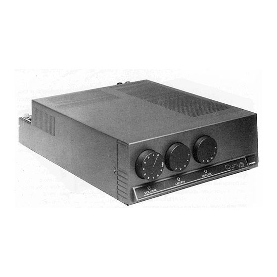
Cyrus 1 and Cyrus 2 Manual
CYRUS AMPLIFIERS
INTRODUCTION
Congratulations on your purchase of the Cyrus integrated stereo amplifier.
The Cyrus range of amplifiers are precision manufactured to the highest
standards and specifications. This results in a highly consistent and
reliable product.
This manual contains installation and operating instructions to enable the
user to connect up and operate the amplifier correctly, thus ensuring the
greatest satisfaction and long term use.
WARNINGS
Your Cyrus amplifier is factory set to operate from a fixed mains supply
voltage. This voltage is marked on a label on the rear of the unit. Before
connecting, check that this voltage is the same as your mains supply.
BEFORE CONNECTING to the mains supply ensure that the On/Off switch
is set to off (down).
DO NOT remove the amplifier cover under any circumstances.
DO NOT make any connections to, or disconnections from the amplifier
unless the amplifier is OFF and the VOLUME control is set to "MIN".
DO NOT change the position of the Selector switches unless the VOLUME
control is set to "MIN".
DO NOT ever select tape on both selector switches at the same time.
DO NOT allow the positive and negative speaker leads to touch.
DO NOT obstruct the ventilation grille on the top of the amplifier. Ensure
the unit has adequate all round ventilation.
Advertisement
Table of Contents

Related Manuals for Cyrus 1


Summary of Contents for Cyrus 1
- Page 1 WARNINGS Your Cyrus amplifier is factory set to operate from a fixed mains supply voltage. This voltage is marked on a label on the rear of the unit. Before connecting, check that this voltage is the same as your mains supply.
- Page 2 INSTALLATION MAINS SUPPLY A label at the rear of your Cyrus amplifier shows the appropriate mains supply voltage and fuse rating of the unit. If the Tnains supply voltage in your area is different, contact your dealer or a Mission service organisation.
- Page 3 • SITING THE AMPLIFIER Your Cyrus amplifier can be sited as a free standing unit or stacked with other units in an audio rack. However, since the power amplifier produces a substantial amount of heat, positioning the unit at the bottom of the rack should be avoided.
- Page 4 Refer to the wiring diagram of your particular Cyrus amplifier for connection details. For best results, the loudspeaker cables used should be of high purity copper and as short as possible. We strongly recommend our own Mission or Cyrus loudspeaker cables.
- Page 5 Cyrus Two Installation Diagram IN CASE OF TROUBLE CYRUS I AND CYRUS II THE POWER L.E.D. DOES NOT ILLUMINATE AND THERE IS NO SOUND Check that the unit is plugged into the mains socket, and the power, switch is ON.
- Page 6 relevant source is at fault. Check input and loudspeaker connections of the channel without sound. Check loudspeaker fuse if any. Interchange the loudspeaker connections between Left and Right channels. Observe whether the fault changes over. If so then the amplifier has a faulty channel.
- Page 7 CYRUS I AMPLIFIER 1. Volume Control: Adjusts the power amplifier output level to the Loudspeakers from zero to the maximum level. 2. Balance Control: Adjustment of the Balance Control knob swings the output level to the left or right Loudspeaker by a maximum of 5 dB.
- Page 8 Warning: Do not select 'Tape" position on both selector switches simultaneously. This may cause feedback problems in the tape deck, if it is in the record mode. 5. Power Switch: Switches the power amplifier section of the unit On (up) and Off (down).
- Page 9 15. IEC Mains Socket: The mains supply is connected to the unit via this socket. It has an integral fuse which can only be removed after the mains lead is disconnected. TECHNICAL DATA (REFERENCE TO IHF202) CYRUS I INTEGRATED AMPLIFIER Input Sensitivity (Ref. 1W O/P) Phono MC 0.04 mV Phono MM 0.40 mV Line (CD,Aux,etc.) 65 mV...
- Page 10 Phono MC 31 dB Phono MM 31 dB Line Infinite Maximum Output Level Tape out 11 Vrms Power Amp out 17 Vrms Input Impedance Phono MC 47 KOhms +100 pF Phono MM 47 KOhms +100 pF Line 14 KOhms Output Impedance Tape out 150 Ohms +2.2 MF Power Amp 0.08 Ohms...
- Page 11 Damping Factor (20Hz - 20KHz) Dynamic Headroom 1.4 dB Slew Factor (Input Filter by-passed) Distortion (THD) 1KHz full power 8 Ohms 0.003% 4 Ohms 0.004% 20KHz full power 8 Ohms 0.015% 4 Ohms 0.025% OPERATING INSTRUCTIONS CYRUS II AMPLIFIER FRONT PANEL...
- Page 12 1. Volume Control: Adjusts the power amplifier output level to the Loudspeakers from zero to the maximum level. 2. Balance Control: Adjustment of the Balance Control knob swings the output level to the left or right Loudspeaker by a maximum of 5 dB.
- Page 13 5. Power Switch: Switches the power amplifier section of the unit On (up) and Off (down). The preamplifier section is powered as soon as the unit is connected to the mains supply This feature helps stabilize the operating temperature of the preamplifier, and optimize the sound quality on switch- 6.
- Page 14 14. PSX Socket: Input for connection to the optional external DC power supply, Cyrus PSX. The socket is fitted with a blanking cover which your dealer will remove to enable connection of your PSX.
- Page 15 Input Overload Phono MC 31 dB Phono MM 31 dB Line Infinite Maximum Output Level Tape out 11 Vrms Power Amp out 24 Vrms Input Impedance Phono MC 100 Ohms + 6.8 nF Phono MM 47 KOhms + 100 pF Line 14 KOhms Output Impedance Tape out 150 Ohms + 2.2 MF...
- Page 16 CYRUS PSX POWER SUPPLY INTRODUCTION: The PSX unit can be connected to either a Cyrus II or 767 LFAU providing a separate DC power supply to the power amplifier section of that unit. The internal power supply of the Cyrus II or LFAU will now be totally dedicated...
- Page 17 Mission service organisation make certain adjustments to your Cyrus II or 767 LFAU before connecting the PSX power supply. 2. Once the Cyrus II or 767 LFAU has been adjusted for use with the PSX, the power amplifier will not function without the PSX connected and switched on.
- Page 18 N.America/Far East- 100/120 = T4A/20mm SITING THE PSX As with your Cyrus amplifier, the PSX may be free standing or stacked in an audio rack. The PSX must be sited in a position which allows adequate, unrestricted airflow around the unit. It should never be placed in a position close to a source of heat, or exposed to direct sunlight for long periods of time.
- Page 19 When the PSX has been added to your system, you will notice that the power switch on your Cyrus II or 767 LFAU is ineffective in turning your system on. The reason for this is, that the PSX is now in control of power to the power amplifier section of that unit, and the On/Off switch on the PSX unit should be used to switch the amplifier On or Off.
- Page 20 NOTE: In Cyrus II or 767 LFAU/PSX combination, the power switch of the Cyrus II or 767 LFAU' is ineffective, as far as the operation of the system is concerned. The power switch may be turned on (up) to illuminate the L.E.D.
- Page 21 Refer the amplifier and the PSX to your dealer. NO SOUND FROM ANY SPEAKER WHEN PHONO MODE IS SELECTED Check that the Cyrus II is plugged in the mains socket, and the power switch is On. HUM OR CRACKLING SOUND FROM ONE OR BOTH SPEAKERS Check there are no faulty connections along the speaker cables and the interconnect cables.
Need help?
Do you have a question about the 1 and is the answer not in the manual?
Questions and answers