
Related Manuals for Dell EMC PowerEdge XR2


Summary of Contents for Dell EMC PowerEdge XR2
- Page 1 Dell EMC PowerEdge XR2 Installation and Service Manual Regulatory Model: E48S Series Regulatory Type: E48S001...
- Page 2 Notes, cautions, and warnings NOTE: A NOTE indicates important information that helps you make better use of your product. CAUTION: A CAUTION indicates either potential damage to hardware or loss of data and tells you how to avoid the problem. WARNING: A WARNING indicates a potential for property damage, personal injury, or death.
-
Page 3: Table Of Contents
Contents 1 Dell EMC PowerEdge XR2 overview.......................7 Supported configurations for the PowerEdge XR2 system..................7 Front view of the system..............................8 Left control panel view...............................10 Right control panel view............................12 Back view of the system..............................13 NIC indicator codes..............................15 Power supply unit indicator codes..........................15 Drive indicator codes................................ - Page 4 Options to manage the pre-operating system applications..................31 System Setup..................................31 Viewing System Setup............................... 31 System Setup details..............................32 System BIOS................................32 iDRAC Settings utility..............................51 Device Settings................................52 Dell Lifecycle Controller..............................52 Embedded system management..........................52 Boot Manager...................................52 Viewing Boot Manager..............................52 Boot Manager main menu............................52 One-shot BIOS boot menu............................
- Page 5 Drives....................................75 Removing a drive blank............................. 75 Installing a drive blank..............................76 Removing a drive................................77 Installing a drive................................78 Removing the drive from the drive carrier......................79 Installing a drive into the drive carrier........................80 System memory................................81 Removing a memory module............................ 82 Installing a memory module............................
- Page 6 System board jumpers and connectors........................125 System board jumper settings............................126 Disabling forgotten password............................127 8 Getting help............................... 128 Contacting Dell................................128 Documentation feedback.............................. 128 Accessing system information by using QRL......................128 Quick Resource Locator for PowerEdge XR2.......................129 Receiving automated support with SupportAssist ....................129 Contents...
-
Page 7: Dell Emc Poweredge Xr2 Overview
Dell EMC PowerEdge XR2 overview The PowerEdge XR2 is a 1U, dual socket rack system with 8 x 2.5 inch drives system and supports up to: • Two Intel Xeon Processor Scalable Family processors • 16 DIMM slots • Integrated M.2 module •... -
Page 8: Front View Of The System
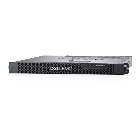
Figure 1. Supported configuration for a PowerEdge XR2 system Front view of the system The front view of the system displays the features available on the front of the system. Figure 2. Front view of the system Dell EMC PowerEdge XR2 overview... - Page 9 Information tag also contains the iDRAC secure default password. Common Access Card Allows for an additional form of authentication for data encryption. (CAC) Or Smart Card Reader Dell EMC PowerEdge XR2 overview...
-
Page 10: Left Control Panel View
The indicator turns solid amber if • Check the System Event Log to determine if the drive there is a drive error. has an error. • Run the appropriate Online Diagnostics test. Restart the system and run embedded diagnostics (ePSA). Dell EMC PowerEdge XR2 overview... - Page 11 Indicates that the iDRAC Quick Sync 2 If the LED fails to turn on, reseat the left control panel feature is turned off. Press the iDRAC Quick flex cable and check. If the problem persists, see the Getting help section. Dell EMC PowerEdge XR2 overview...
-
Page 12: Right Control Panel View
Figure 5. Right control panel Table 5. Right control panel Item Indicator or button Icon Description Indicates if the system is turned Power button on or off. Press the power button to manually turn on or off the system. Dell EMC PowerEdge XR2 overview... -
Page 13: Back View Of The System
User’s Guide at Dell.com/ idracmanuals. Back view of the system The back view of the system displays the features available on the back of the system. Figure 6. Back view of the system Dell EMC PowerEdge XR2 overview... - Page 14 To reset iDRAC using system ID, ensure that the system ID button is enabled in the iDRAC setup. • If the system stops responding during POST, press and hold the system ID button (for more than five seconds) to enter the BIOS progress mode. Dell EMC PowerEdge XR2 overview...
-
Page 15: Nic Indicator Codes
AC power supply units (PSUs) have an illuminated translucent handle that serves as an indicator. The indicator shows whether power is present or if a power fault has occurred. Figure 8. AC PSU status indicator AC PSU status indicator/handle Dell EMC PowerEdge XR2 overview... - Page 16 PSUs, which support only 240 V. When two identical PSUs receive different input voltages, they can output different wattages, and trigger a mismatch. CAUTION: If two PSUs are used, they must be of the same type and have the same maximum output power. Dell EMC PowerEdge XR2 overview...
-
Page 17: Drive Indicator Codes
Flashes amber four times per second Drive failed. Flashes green slowly Drive rebuilding. Solid green Drive online. Flashes green for three seconds, amber for three seconds, and Rebuild stopped. then turns off after six seconds Dell EMC PowerEdge XR2 overview... -
Page 18: Lcd Panel
To view the Home screen, press one of the three navigation buttons (Select, Left, or Right). To navigate to the Home screen from another menu, complete the following steps: Press and hold the navigation button till the up arrow is displayed. Dell EMC PowerEdge XR2 overview... -
Page 19: Setup Menu
Express Service Code and Service Tag. Alternatively, the information may be on a sticker on the chassis of the system. The mini Enterprise Service Tag (EST) is found on the back of the system. This information is used by Dell to route support calls to the appropriate personnel. Dell EMC PowerEdge XR2 overview... - Page 20 Figure 11. Locating Service Tag of your system information tag (front view) information tag (back view) OpenManage Mobile (OMM) label iDRAC MAC address and iDRAC secure password label Service Tag Dell EMC PowerEdge XR2 overview...
-
Page 21: Documentation Resources
Dell OpenManage Essentials, see the Dell OpenManage Essentials User’s Guide. For information about installing and using Dell Dell.com/serviceabilitytools SupportAssist, see the Dell EMC SupportAssist Enterprise User’s Guide. For understanding the features of Dell Lifecycle Dell.com/idracmanuals Controller, see the Dell Lifecycle Controller User’s Guide. - Page 22 Task Document Location For information about partner programs enterprise Dell.com/openmanagemanuals systems management, see the OpenManage Connections Enterprise Systems Management documents. Working with the Dell For information about understanding the features Dell.com/storagecontrollermanuals PowerEdge RAID controllers of the Dell PowerEdge RAID controllers (PERC), Software RAID controllers, or BOSS card and deploying the cards, see the Storage controller documentation.
-
Page 23: Technical Specifications
Technical specifications The technical and environmental specifications of your system are outlined in this section. Topics: • System dimensions • Chassis weight • Processor specifications • PSU specifications • System battery specifications • Expansion bus specifications • Memory specifications • Drive specifications •... -
Page 24: System Dimensions
Chassis weight Table 13. Chassis weight System Maximum weight (with all drives/SSDs) 8 x 2.5 inch drive system 13.00 Kg (28 lb) Processor specifications The PowerEdge XR2 system supports up to two Intel Xeon Processor Scalable Family processors. Technical specifications... -
Page 25: Psu Specifications
The PowerEdge XR2 system supports CR 2032 3.0-V lithium coin cell system battery. Expansion bus specifications The PowerEdge XR2 system supports PCI express (PCIe) generation three expansion cards, which must be installed on the system board using expansion card risers. The XR2 system supports two types of expansion card risers. -
Page 26: Drive Specifications
The PowerEdge XR2 system supports two Network Interface Controller (NIC) ports on the back panel, which have two 1 Gbps configuration. Serial connector The serial connector connects a serial device to the system. The PowerEdge XR2 system supports one serial connector on the back panel, which is a 9-pin connector, Data Terminal Equipment (DTE), 16550-compliant. Technical specifications... -
Page 27: Vga Ports
VGA ports The Video Graphic Array (VGA) port enables you to connect the system to a VGA display. The PowerEdge XR2 system supports two 15-pin VGA ports on the front and back panels . Internal Dual MicroSD Module The PowerEdge XR2 system supports two optional flash memory card slots with an internal dual MicroSD module. -
Page 28: Particulate And Gaseous Contamination Specifications
Table 20. Relative humidity specifications Relative humidity Specifications Storage 5% to 95% RH with 33°C (91°F) maximum dew point. Atmosphere must be non-condensing at all times. Operating 5% to 85% relative humidity with 29°C (84.2°F) maximum dew point. Table 21. Maximum vibration specifications Maximum vibration Specifications Operating... -
Page 29: Standard Operating Temperature
60% relative humidity. NOTE: This condition applies to data center and non-data center environments. NOTE: PowerEdge XR2 offers an optional kit to meet the dust and sand requirements per MIL-STD-810G, Method 510.5, Procedure I. Table 25. Gaseous contamination specifications Gaseous contamination Specifications Copper coupon corrosion rate <300 Å/month per Class G1 as defined by ANSI/ISA71.04-1985. - Page 30 Expanded operating temperature Specifications For temperatures between 35°C and 45°C, de-rate maximum allowable temperature by 1°C per 175 m above 950 m (1°F per 319 ft). ≤ 1% of annual operating hours –5°C to 55°C at 5% to 90% RH with 29°C dew point. NOTE: Outside the standard operating temperature (10°C to 35°C), the system can operate down to –5°C or up to 55°C for a...
-
Page 31: Pre-Operating System Management Applications
Pre-operating system management applications You can manage basic settings and features of a system without booting to the operating system by using the system firmware. Topics: • Options to manage the pre-operating system applications • System Setup • Dell Lifecycle Controller •... -
Page 32: System Setup Details
System Setup details The System Setup Main Menu screen details are explained as follows: Option Description System BIOS Enables you to configure BIOS settings. iDRAC Settings Enables you to configure the iDRAC settings. The iDRAC settings utility is an interface to set up and configure the iDRAC parameters by using UEFI (Unified Extensible Firmware Interface). -
Page 33: System Information
Option Description Legacy network settings are managed from the Device Settings menu. Integrated Devices Specifies options to manage integrated device controllers and ports, specifies related features and options. Serial Specifies options to manage the serial ports, its related features and options. Communication System Profile Specifies options to change the processor power management settings, memory frequency. - Page 34 Option Description System Specifies the contact information of the system manufacturer. Manufacturer Contact Information System CPLD Specifies the current version of the system complex programmable logic device (CPLD) firmware. Version UEFI Compliance Specifies the UEFI compliance level of the system firmware. Version Memory Settings You can use the Memory Settings screen to view all the memory settings and enable or disable specific memory functions, such as system...
-
Page 35: Processor Settings
Option Description NOTE: The Memory Operating Mode option can have different default and available options based on the memory configuration of your system. Current State of Specifies the current state of the memory operating mode. Memory Operating Mode Node Interleaving Specifies if Non-Uniform Memory Architecture (NUMA) is supported. - Page 36 Option Description Maximum data rate indicates that the BIOS runs the communication links at the maximum frequency supported by the processors. You can also select specific frequencies that the processors support, which can vary. For best performance, you should select Maximum data rate. Any reduction in the communication link frequency affects the performance of non-local memory accesses and cache coherency traffic.
- Page 37 Option Description Option Description Family-Model- Specifies the family, model, and stepping of the processor as defined by Intel. Stepping Brand Specifies the brand name. Level 2 Cache Specifies the total L2 cache. Level 3 Cache Specifies the total L3 cache. Number of Cores Specifies the number of cores per processor.
-
Page 38: Boot Settings
Option Description Option Description Capacity Specifies the total capacity of the drive. This field is undefined for removable media devices such as optical drives. Boot Settings You can use the Boot Settings screen to set the boot mode to either BIOS or UEFI. It also enables you to specify the boot order. •... -
Page 39: Network Settings
Option Description attempted to boot. When this option is set to Enabled, all drives are attempted to boot in the order selected in the Hard-Disk Drive Sequence. This option is not enabled for UEFI Boot Mode. This option is set to Disabled by default. -
Page 40: Network Settings Screen Details
Viewing Network Settings To view the Network Settings screen, perform the following steps: Turn on, or restart your system. Press F2 immediately after you see the following message: F2 = System Setup NOTE: If your operating system begins to load before you press F2, wait for the system to finish booting, and then restart your system and try again. - Page 41 On the System Setup Main Menu screen, click System BIOS. On the System BIOS screen, click Network Settings. On the Network Settings screen, click UEFI iSCSI Settings. UEFI iSCSI Settings details The UEFI iSCSI Settings screen details are explained as follows: Option Description iSCSI Initiator...
- Page 42 Option Description Integrated RAID Enables or disables the integrated RAID controller. This option is set to Enabled by default. Controller Embedded NIC1 NOTE: The Embedded NIC1 and NIC2 options are only available on systems that do not have Integrated and NIC2 Network Card 1.
- Page 43 Option Description Table 29. Slot Disablement Option Description Enables or disables or only the boot driver is disabled Slot 1 for the PCIe slot 1. This option is set to Enabled by default. Enables or disables or only the boot driver is disabled Slot 2 for the PCIe slot 2.
- Page 44 Serial Communication details The Serial Communication screen details are explained as follows: Option Description Serial Selects serial communication devices (Serial Device 1 and Serial Device 2) in BIOS. BIOS console redirection can Communication also be enabled, and the port address can be specified. This option is set to Auto by default. Enables the COM port or Console Redirection options.
- Page 45 On the System Setup Main Menu screen, click System BIOS. On the System BIOS screen, click System Profile Settings. System Profile Settings details The System Profile Settings screen details are explained as follows: Option Description System Profile Sets the system profile. If you set the System Profile option to a mode other than Custom, the BIOS automatically sets the rest of the options.
-
Page 46: System Security
Option Description NOTE: When C States is set to Enabled in the Custom mode, changing the Monitor/Mwait setting does not impact the system power or performance. CPU Interconnect Enables or disables the CPU Interconnect Bus Link Power Management. This option is set to Enabled by default. Bus Link Power Management PCI ASPM L1 Link... -
Page 47: Options Description
Option Description Enables you to control the reporting mode of the TPM. The TPM Security option is set to Off by default. You can only modify the TPM Status TPM Activation, and the Intel TXT fields if the TPM Status field is set to either On with Pre-boot Measurements or On without Pre-boot Measurements. - Page 48 Option Description Options Description Audit Mode In Audit mode, PK is not present. The BIOS does not authenticate programmatic updates to the policy objects, and transitions between modes. Audit Mode is useful for programmatically determining a working set of policy objects. BIOS performs signature verification on pre-boot images and logs results in the image Execution Information Table, but executes the images whether they pass or fail verification.
-
Page 49: Using Your System Password To Secure Your System
NOTE: Password protection does not take effect until the system reboots. Using your system password to secure your system About this task If you have assigned a setup password, the system accepts your setup password as an alternate system password. Steps Turn on or reboot your system. - Page 50 • You cannot disable or change an existing system password. NOTE: You can use the password status option with the setup password option to protect the system password from unauthorized changes. Redundant OS Control You can use the Redundant OS Control screen to set the redundant OS info for redundant OS control. It enables you to set up a physical recovery disk on your system.
-
Page 51: Idrac Settings Utility
Miscellaneous Settings You can use the Miscellaneous Settings screen to perform specific functions such as updating the asset tag and changing the system date and time. Viewing Miscellaneous Settings To view the Miscellaneous Settings screen, perform the following steps: Turn on, or restart your system. Press F2 immediately after you see the following message: F2 = System Setup NOTE:... -
Page 52: Device Settings
For more information about using iDRAC, see Dell Integrated Dell Remote Access Controller User's Guide at Dell.com/idracmanuals. Device Settings Device Settings enables you to configure device parameters. Dell Lifecycle Controller Dell Lifecycle Controller (LC) provides advanced embedded systems management capabilities including system deployment, configuration, update, maintenance, and diagnosis. -
Page 53: One-Shot Bios Boot Menu
Menu item Description One-shot Boot Enables you to access boot menu, where you can select a one-time boot device to boot from. Menu Launch System Enables you to access System Setup. Setup Launch Lifecycle Exits the Boot Manager and invokes the Dell Lifecycle Controller program. Controller System Utilities Enables you to launch System Utilities menu such as System Diagnostics and UEFI shell. -
Page 54: Installing And Removing System Components
Installing and removing system components Safety instructions WARNING: Whenever you need to lift the system, get others to assist you. To avoid injury, do not attempt to lift the system by yourself. WARNING: Opening or removing the system cover while the system is powered on may expose you to a risk of electric shock. CAUTION: Do not operate the system without the cover for a duration exceeding five minutes. -
Page 55: Optional Front Bezel
Optional front bezel An optional metal bezel is mounted on the front of the system to display system branding. A lock on the bezel is used to protect unauthorized access to the drives. There are two versions of bezel available: •... -
Page 56: Removing The Bezel Filter
Steps Align the thumb screws on the bezel with the rack ears on the front of the system. Using a Phillips #2 screwdriver, tighten the thumb screws to secure the bezel to the system chassis. Figure 14. Installing the front bezel Removing the bezel filter Prerequisites Follow the safety guidelines listed in... -
Page 57: Installing The Bezel Filter
Figure 15. Removing the bezel filter Next step Follow the procedure listed in After working inside your system. If applicable, install the front bezel to the system. Installing the bezel filter Prerequisites Follow the safety guidelines listed in Safety instructions. Remove the front bezel. -
Page 58: System Cover
Figure 16. Installing the bezel filter Next steps Follow the procedure listed in After working inside your system. If applicable, install the front bezel to the system. System cover System cover provides security for the entire system and also helps in maintaining proper air flow inside the system. Removing the system cover Prerequisites Follow the safety guidelines listed in... -
Page 59: Installing The System Cover
Figure 17. Removing the system cover Next step Follow the procedure listed in After working inside your system. Installing the system cover Prerequisites Follow the safety guidelines listed in Safety instructions. Follow the procedure listed in Before working inside your system. -
Page 60: Front Io Board
Figure 18. Installing the system cover Next step Follow the procedure listed in After working inside your system. Front IO board The front IO board features multiple expansion slots and storage options: • Two M.2 ports • eSATA port • Internal USB port 2.0 •... -
Page 61: Installing The Front Io Board
Figure 19. Removing the front IO board Next steps Install the front IO board. Follow the procedure listed in After working inside your system. Installing the front IO board Prerequisite Follow the safety guidelines listed in Safety instructions. Steps Lower the front IO board aligning the connectors on the board with the slots on the front of the system. Using a Phillips #2 screwdriver, replace the screws that secure the IO board to the chassis. -
Page 62: Common Access Card (Cac) Or Smart Card Reader
Figure 20. Installing the front IO board Next steps Reconnect all cables to the IO board. NOTE: Ensure that the cables inside the system are routed along the chassis wall and secured using the cable securing bracket. Install the cooling fan. Follow the procedure listed in After working inside your system. - Page 63 Figure 21. Removing the Smart Card Reader bracket Using the screwdriver, remove the four screws securing the Smart Card Reader to the chassis. Lift the Smart Card Reader out of the system. Installing and removing system components...
-
Page 64: Installing The Smart Card Reader
Figure 22. Removing the Smart Card Reader Next steps Install the front IO board. Follow the procedure listed in After working inside your system. Installing the Smart Card Reader Prerequisites Follow the safety guidelines listed in Safety instructions. Remove the front IO board. Steps Align the Smart Card Reader with the screw holes on the chassis. - Page 65 Figure 23. Installing the Smart Card Reader Using a Phillips #2 screwdriver, replace the screws that secure the Smart Card Reader bracket to the chassis. Installing and removing system components...
-
Page 66: Air Shroud
Figure 24. Installing the Smart Card Reader bracket Next steps Reconnect all cables to the Smart Card Reader. NOTE: Ensure that the cables inside the system are routed along the chassis wall and secured using the cable securing bracket. Follow the procedure listed in After working inside your system. -
Page 67: Installing The Air Shroud
Figure 25. Removing the air shroud Next steps If applicable, install the air shroud. Follow the procedure listed in After working inside your system. Installing the air shroud Prerequisites Follow the safety guidelines listed in Safety instructions. Follow the procedure listed in Before working inside your system. -
Page 68: Internal Perc Riser
Figure 26. Installing the air shroud Holding the touch points, lower the air shroud into the system until it is firmly seated. When firmly seated, the memory socket numbers marked on the air shroud align with the respective memory sockets. Next step Follow the procedure listed in After working inside your... - Page 69 Figure 27. Removing the internal MiniPERC riser Turn the riser to access the PERC cable. Using a Phillips #2 screwdriver, loosen the screws that connect the PERC cable to the MiniPERC riser. Figure 28. Removing the PERC cable from the riser Next steps Follow the procedure listed in After working inside your...
-
Page 70: Installing The Internal Miniperc Riser
Install the internal MiniPERC riser. Installing the internal MiniPERC riser Prerequisites Follow the safety guidelines listed in Safety instructions. Follow the procedure listed in Before working inside your system. Steps Using a Phillips #2 screwdriver, tighten the screws that connect the PERC cable to the MiniPERC riser. Figure 29. -
Page 71: Cooling Fans
Figure 30. Installing the internal MiniPERC riser Lift the plunger to lock the riser in place. Next steps Close the cable guiding latch. Follow the procedure listed in After working inside your system. Cooling fans The cooling fans are integrated into the system to dissipate the heat generated by the functioning of the system. These fans provide cooling for the processors, expansion cards, and memory modules. -
Page 72: Installing The Cooling Fan
Remove the air shroud. Step Disconnect the cooling fan cable connected to the system board connector and lift the fan out holding the blue touch point. Figure 31. Removing the cooling fan Next steps Install the cooling fan. Install the air shroud. Follow the procedure listed in After working inside your system. -
Page 73: Intrusion Switch
Figure 32. Installing cooling fan Next steps Install the internal riser. Install the cooling shroud. Follow the procedure listed in After working inside your system. Intrusion switch The Chassis Intrusion Switch is activated when the cover of your system is removed while your system is on. The system event logs [SEL] records the number of times the cover is removed when the system is turned on.. -
Page 74: Installing The Intrusion Switch
Figure 33. Removing the intrusion switch Next steps Installing intrusion switch. Follow the procedure listed in After working inside your system. Installing the intrusion switch Prerequisites Follow the safety guidelines listed in Safety instructions. Follow the procedure listed in Before working inside your system. -
Page 75: Drives
Figure 34. Installing intrusion switch Next steps Install internal PERC riser. Install air shroud. Follow the procedure listed in After working inside your system. Drives Drives are supplied in hot swappable drive carriers that fit in the drive slots. CAUTION: Before attempting to remove or install a drive while the system is running, see the documentation for the storage controller card to ensure that the host adapter is configured correctly. -
Page 76: Installing A Drive Blank
CAUTION: Mixing drive blanks from previous generations of PowerEdge servers is not supported. Step Press the release button, and slide the drive blank out of the drive slot. Figure 35. Removing a drive blank Next steps Install a drive or a drive blank. -
Page 77: Removing A Drive
Figure 36. Installing a drive blank Next step If removed, install the front bezel. Removing a drive Prerequisites Follow the safety guidelines listed in Safety instructions. Using the management software, prepare the drive for removal. If the drive is online, the green activity or fault indicator flashes while the drive is turning off. When the drive indicators are off, the drive is ready for removal. -
Page 78: Installing A Drive
Figure 37. Removing a drive Next steps Install a drive. If you are not replacing the drive immediately, insert a drive blank in the empty rive slot to maintain proper system cooling. Installing a drive Prerequisites CAUTION: Before attempting to remove or install a drive while the system is running, see the documentation for the storage controller card to ensure that the host adapter is configured correctly to support drive removal and insertion. -
Page 79: Removing The Drive From The Drive Carrier
Figure 38. Installing a drive Next step If applicable, install the front bezel. Removing the drive from the drive carrier Prerequisite Follow the safety guidelines listed in Safety instructions. CAUTION: Mixing drives from previous generations of PowerEdge servers is not supported. Steps Using a Phillips #1 screwdriver, remove the screws from the slide rails on the drive carrier. -
Page 80: Installing A Drive Into The Drive Carrier
Figure 39. Removing the drive from the drive carrier Lift the drive out of the drive carrier. Next step If applicable, install the drive into the drive carrier. Installing a drive into the drive carrier Prerequisites Follow the safety guidelines listed in Safety instructions. -
Page 81: System Memory
Figure 40. Installing a drive into the drive carrier Using a Phillips #1 screwdriver, secure the drive to the drive carrier with screws. System memory The system supports DDR4 registered DIMMs (RDIMMs) load reduced DIMMs (LRDIMMs). System memory holds the instructions that are executed by the processor. -
Page 82: Removing A Memory Module
Removing a memory module Prerequisites Follow the safety guidelines listed in Safety instructions. Follow the procedure listed in Before working inside your system. WARNING: Allow the memory modules to cool after you power off the system. Handle the memory modules by the card edges and avoid touching the components or metallic contacts on the memory module. -
Page 83: Processors And Heat Sinks
CAUTION: Do not apply pressure at the center of the memory module; apply pressure at both ends of the memory module evenly. NOTE: The memory module socket has an alignment key that enables you to install the memory module in the socket in only one orientation. -
Page 84: Removing The Processor From The Processor And Heat Sink Module
If applicable, remove the air shroud. Steps Using a Torx #T30 screwdriver, loosen the screws on the heat sink in the order below: Loosen the first screw three turns. b Loosen the second screw completely. Return to the first screw and loosen it completely. NOTE: It is normal for the heat sink to slip off the blue retention clips when the screws are partially loosened, continue to loosen the screw(s). - Page 85 Push the retaining clips on the processor bracket to unlock the bracket from the heat sink. Figure 44. Loosening the processor bracket Lift the bracket and the processor away from the heat sink, and place the processor connector side down on the processor tray. Flex the outer edges of the bracket to release the bracket from the processor.
-
Page 86: Installing The Processor Into A Processor And Heat Sink Module
Installing the processor into a processor and heat sink module Prerequisite Follow the safety guidelines listed in Safety instructions. Steps Place the processor in the processor tray. NOTE: Ensure that the pin 1 indicator on the processor tray is aligned with the pin 1 indicator on the processor. Flex the outer edges of the bracket around the processor ensuring that the processor is locked into the clips on the bracket. - Page 87 Figure 47. Applying thermal grease on top of the processor Place the heat sink on the processor and push down on the base of the heat sink until the bracket locks onto the heat sink. NOTE: • Ensure that the two guide pin holes on the bracket match the guide holes on the heat sink. •...
-
Page 88: Installing A Processor And Heat Sink Module
Figure 48. Installing the heat sink onto the processor Next steps Install the processor and heat sink module. Install the air shroud. Follow the procedure listed in After working inside your system. Installing a processor and heat sink module Prerequisites CAUTION: Never remove the heat sink from a processor unless you intend to replace the processor. -
Page 89: Expansion Cards And Expansion Card Risers
NOTE: Ensure that the PHM is held parallel to the system board to prevent damaging the components. Push the blue retention clips inward to allow the heat sink to drop into place. Supporting the heat sink with one hand. Using the Torx #T30 screwdriver, tighten the screws on the heat sink in the order below: Partially tighten the first screw (approximately 3 turns). - Page 90 Remove the internal MiniPERC riser (applicable to expansion card riser 2). Step Hold the touch points, and lift the expansion card riser. Figure 50. Removing low profile riser right Installing and removing system components...
-
Page 91: Installing An Expansion Card Riser
Figure 51. Removing low profile riser left Next step Install the expansion card riser. Installing an expansion card riser Prerequisite Follow the safety guidelines listed in Safety instructions. Steps If removed, install the expansion cards into the expansion card riser. Installing and removing system components... - Page 92 Figure 52. Installing low profile riser right Holding the touch points, align the expansion card riser with the connector and the riser guide pin on the system board. Lower the expansion card riser into place until the expansion card riser connector is fully seated in the connector. Installing and removing system components...
-
Page 93: Removing The Expansion Card From The Expansion Card Riser
Figure 53. Installing low profile riser left Next steps Replace the internal MiniPERC riser (applicable to expansion card riser 2). Follow the procedure listed in After working inside your system. Install any device drivers required for the card as described in the documentation for the card. Removing the expansion card from the expansion card riser Prerequisites Follow the safety guidelines listed in... - Page 94 Figure 54. Removing expansion card from low profile riser If the expansion card is not going to be replaced, install a filler bracket. Figure 55. Installing filler bracket for low profile riser Next steps Install expansion card into the expansion card riser.
-
Page 95: Installing An Expansion Card Into The Expansion Card Riser
NOTE: You must install a filler bracket over an empty expansion card slot to maintain Federal Communications Commission (FCC) certification of the system. The brackets also keep dust and dirt out of the system and aid in proper cooling and airflow inside the system. Installing an expansion card into the expansion card riser Prerequisites Follow the safety guidelines listed in... -
Page 96: Optional Idsdm Or Vflash Module
Figure 57. Installing expansion card into low profile riser Next steps If applicable, connect the cables to the expansion card. Install the expansion card riser. If applicable, install air shroud. Follow the procedure listed in After working inside your system. Install any device drivers required for the card as described in the documentation for the card. -
Page 97: Installing The Idsdm Or Vflash Module
Figure 58. Removing the optional IDSDM/vFlash card NOTE: There are two dip switches on the IDSDM/vFlash card for write-protection. Next step Install the optional IDSDM/vFlash card. Installing the IDSDM or vFlash module Prerequisite Follow the safety guidelines listed in Safety instructions. -
Page 98: Removing The Microsd Card
Figure 59. Installing the IDSDM or vFlash module Next steps Install the MicroSD cards. NOTE: Reinstall the MicroSD cards into the same slots based on the labels you had marked on the cards during removal. Install the air shroud. Follow the procedure listed in After working inside your system. -
Page 99: Installing The Microsd Card
Installing the MicroSD card Prerequisites Follow the safety guidelines listed in Safety instructions. NOTE: To use an MicroSD card with your system, ensure that the Internal SD Card Port is enabled in System Setup. NOTE: If reinstalling, ensure that you install the MicroSD cards into the same slots based on the labels you had marked on the cards during removal. -
Page 100: Installing The Lom Riser Card
Figure 60. Removing the LOM riser card Next step Install the LOM riser card. Installing the LOM riser card Prerequisite Follow the safety guidelines listed in Safety instructions. Steps Orient the LOM riser card to fit through the Ethernet connectors or the SFP slot on the system. Press the LOM riser card until the card is firmly seated on the system board connector and the two blue plastic snap hold the LOM riser card in place. -
Page 101: Hard Drive Backplane
Follow the procedure listed in After working inside your system. Hard drive backplane Depending on your system configuration, the hard drive backplanes supported in PowerEdge XR2 are listed here: Table 33. Supported backplane options for PowerEdge XR2 systems System Supported drives options PowerEdge XR2 2.5 inch (x8) SAS, SATA backplane... -
Page 102: Removing The Hard Drive Backplane
Front IO power cable connector Removing the hard drive backplane Prerequisites CAUTION: To prevent damage to the drives and backplane, remove the hard drives from the system before removing the backplane. CAUTION: Note the number of each hard drive and temporarily label them before you remove the hard drive so that you can replace them in the same location. -
Page 103: Installing The Hard Drive Backplane
Installing the hard drive backplane Prerequisite Follow the safety guidelines listed in Safety instructions. Steps Use the hooks on the system as guides to align the slots on the backplane. Lower the hard drive backplane until the blue release tabs snap into place. Figure 64. -
Page 104: Cable Routing
Cable routing Figure 65. Cable routing - 8 x 2.5 hard drive backplane with PERC FIO power cable backplane signal cable backplane power cable cable routing clip power interposer board SAS cable internal MiniPERC riser hard drive backplane Installing and removing system components... -
Page 105: System Battery
Figure 66. Cable routing - 8 x 2.5 hard drive backplane with onboard SATA FIO power cable backplane signal cable backplane power cable cable routing clip power interposer board SATA cable SATA cable hard drive backplane System battery The system battery is used for low-level system functions such as powering the real-time and date settings of the system. Replacing the system battery Prerequisites WARNING:... -
Page 106: Optional Internal Usb Memory Key
Figure 67. Removing the system battery To install a new system battery, hold the battery with the positive side facing up and slide it under the securing tabs. Press the battery into the connector until it snaps into place. Figure 68. Installing the system battery Next steps Install the expansion card riser If applicable, connect the cables to the expansion card(s). -
Page 107: Power Supply Units
Steps Locate the USB port or USB memory key on the system board. To locate the USB port, see the Internal USB memory key (optional) section. If installed, remove the USB memory key from the USB port. Insert the replacement USB memory key into the USB port. Next steps Follow the procedure listed in After working inside your... -
Page 108: Installing A Power Supply Unit
Figure 69. Removing a power supply unit Next step Install the PSU. Installing a power supply unit Prerequisites Follow the safety guidelines listed in Safety instructions. For systems that support redundant PSU, ensure that both the PSUs are of the same type and have the same maximum output power. -
Page 109: Power Interposer Board
Figure 70. Installing a power supply unit Next steps If you have unlatched the cable management arm, relatch it. For information about the cable management arm, see the system’s rack documentation at Dell.com/poweredgemanuals. Plug the cable into a power outlet. CAUTION: When connecting the power cable to the PSU, secure the cable to the PSU with the strap. -
Page 110: Installing Power Interposer Board
Steps Using a Phillips #2 screwdriver, remove the two screws securing the power interposer board (PIB) to the system. Slide the board towards the front of the system and then lift it out. Figure 71. Removing a PIB Next step Install the power interposer board. -
Page 111: Control Panel
Figure 72. Installing a PIB Next steps Install PSUs. Install the MiniPERC riser. Install the cooling fans. Install the air shroud. Follow the procedure listed in After working inside your system. Control panel A control panel allows you to manually control the inputs to the server. Your system supports: •... -
Page 112: Installing The Left Control Panel
Steps Disconnect the control panel cable from the system board connector. Using a Phillips #1 screwdriver, remove the screw that secures the control panel to the system. Holding the sides, remove the left control panel assembly away from the system. Figure 73. -
Page 113: Removing The Right Control Panel
Figure 74. Installing the left control panel Next steps Install the air shroud. Install the internal PERC riser. Follow the procedure listed in After working inside your system. Removing the right control panel Prerequisites Follow the safety guidelines listed in Safety instructions. -
Page 114: Installing The Right Control Panel
Figure 75. Removing the right control panel Using a Phillips #1 screwdriver, remove the screw that secures the right control panel to the system. Next step Install the right control panel. Installing the right control panel Prerequisite Follow the safety guidelines listed in Safety instructions. -
Page 115: System Board
Figure 76. Installing the right control panel Next steps Install the MiniPERC riser. Install the hard drive backplane. Install the cooling fan. Follow the procedure listed in After working inside your system. System board A system board (also known as the motherboard) is the main printed circuit board in the system with different connectors used to connect different components or peripherals of the system. - Page 116 Follow the procedure listed in Before working inside your system. Remove the following: Air shroud Expansion cards and risers Internal PERC riser vFlash/IDSDM module Internal USB key (if installed) Processors and heat sink modules Processor blanks (if applicable) CAUTION: To prevent damage to the processor socket when replacing a faulty system board, ensure that you cover the processor socket with the processor dust cover.
-
Page 117: Installing The System Board
Figure 77. Removing the system board Next step Install the system board. Installing the system board Prerequisite Follow the safety guidelines listed in Safety instructions. Steps Unpack the new system board assembly. CAUTION: Do not lift the system board by holding a memory module, processor, or other components. CAUTION: Take care not to damage the system identification button while placing the system board into the chassis. - Page 118 Figure 78. Installing the system board Next steps Install the Trusted Platform Module (TPM). NOTE: The TPM plug-in module is attached to the system board and cannot be removed. A replacement TPM plug-in module is provided for all system board replacements, where a TPM plug-in module was installed. Replace the following: Internal PERC riser Internal USB key...
-
Page 119: Restoring The Service Tag Using Easy Restore
Import your new or existing iDRAC Enterprise license. For more information, see iDRAC User's Guide, at Dell.com/idracmanuals. Restoring the Service Tag using Easy Restore The easy restore feature allows you to restore your service tag, license, UEFI configuration, and the system configuration data after replacing the system board. -
Page 120: Initializing Tpm For Bitlocker Users
NOTE: • Ensure that your operating system supports the version of the TPM module being installed. • Ensure that you download and install the latest BIOS firmware on your system. • Ensure that the BIOS is configured to enable UEFI boot mode. Steps Locate the TPM connector on the system board. - Page 121 Save the settings. Restart your system. Enter System Setup again. On the System Setup Main Menu screen, click System BIOS > System Security Settings. From the Intel TXT option, select On. Installing and removing system components...
-
Page 122: Using System Diagnostics
Using system diagnostics If you experience a problem with your system, run the system diagnostics before contacting Dell for technical assistance. The purpose of running system diagnostics is to test your system hardware without using additional equipment or risking data loss. If you are unable to fix the problem yourself, service and support personnel can use the diagnostics results to help you solve the problem. -
Page 123: System Diagnostic Controls
System diagnostic controls Menu Description Configuration Displays the configuration and status information of all detected devices. Results Displays the results of all tests that are run. System health Provides the current overview of the system performance. Event log Displays a time-stamped log of the results of all tests run on the system. This is displayed if at least one event description is recorded. -
Page 124: Jumpers And Connectors
Jumpers and connectors This topic provides specific information about the jumpers. It also provides some basic information about jumpers and switches and describes the connectors on the board in the system. Jumpers on the system board help to disable the system and setup passwords. You must know the connectors on the system board to install components and cables correctly. -
Page 125: System Board Jumpers And Connectors
System board jumpers and connectors Figure 80. System board jumpers and connectors Table 34. System board jumpers and connectors Item Connector Description FAN6 Cooling fan 6 connector CPU1 Processor socket 1 CPU1_PWR_CONN(P2) CPU1 power connector J_INTRU Intrusion switch connector J_BP_SIG1 Backplane signal connector 1 LFT_CP_CONN Left control panel connector... -
Page 126: System Board Jumper Settings
Item Connector Description RGT_CP_CONN Right control panel connector SYS_PWR_CONN(P1) System power connector J_PIB_SIG1 Power interposer board signal connector 1 J_PIB_SIG2 Power interposer board signal connector 2 J_ACE Internal Dual SD Module J_CP_USB2 Front USB connector J_SATA_A1 Internal SATA A connector J_SATA_C1 Internal SATA C connector PCIE_G3_X8(CPU1) -
Page 127: Disabling Forgotten Password
Table 35. System board jumper settings Jumper Setting Description PWRD_EN The BIOS password feature is enabled. The BIOS password feature is disabled. iDRAC local access is unlocked at next AC power cycle. iDRAC password reset is enabled in F2 iDRAC settings menu. NVRAM_CLR The BIOS configuration settings are retained at system boot. -
Page 128: Getting Help
Getting help Topics: • Contacting Dell • Documentation feedback • Accessing system information by using QRL • Receiving automated support with SupportAssist Contacting Dell Dell provides several online and telephone based support and service options. If you do not have an active internet connection, you can find contact information about your purchase invoice, packing slip, bill, or Dell product catalog. -
Page 129: Quick Resource Locator For Poweredge Xr2
Use your smartphone or tablet to scan the model-specific Quick Resource (QR) code on your Dell PowerEdge system or in the Quick Resource Locator section. Quick Resource Locator for PowerEdge XR2 Figure 81. Quick Resource Locator Receiving automated support with SupportAssist Dell SupportAssist is an optional Dell Services offering that automates technical support for your Dell server, storage, and networking devices.
Need help?
Do you have a question about the PowerEdge XR2 and is the answer not in the manual?
Questions and answers