
Related Manuals for Dell EMC PowerEdge R440


Summary of Contents for Dell EMC PowerEdge R440
- Page 1 Dell EMC PowerEdge R440 Installation and Service Manual Regulatory Model: E45S Series Regulatory Type: E45S001...
- Page 2 Notes, cautions, and warnings NOTE: A NOTE indicates important information that helps you make better use of your product. CAUTION: A CAUTION indicates either potential damage to hardware or loss of data and tells you how to avoid the problem. WARNING: A WARNING indicates a potential for property damage, personal injury, or death.
-
Page 3: Table Of Contents
Contents 1 Dell EMC PowerEdge R440 overview......................8 Front view of the system..............................8 Left control panel view...............................10 Right control panel view............................13 Back view of the system..............................14 Drive indicator codes................................16 NIC indicator codes................................17 Power supply unit indicator codes..........................17 LCD panel.................................. - Page 4 iDRAC configuration................................ 32 Options to set up iDRAC IP address........................32 Log in to iDRAC................................33 Options to install the operating system.........................33 Methods to download firmware and drivers......................33 Downloading drivers and firmware.......................... 34 5 Pre-operating system management applications..................35 Options to manage the pre-operating system applications..................35 System Setup...................................
- Page 5 Removing the intrusion switch..........................73 Installing the intrusion switch........................... 73 Drives....................................74 Removing a drive blank..............................74 Installing a drive blank..............................75 Removing a 2.5 inch drive from a 3.5 inch drive adapter..................76 Installing a 2.5 inch drive into a 3.5 inch drive adapter..................76 Removing a 3.5 inch drive adapter from a 3.5 inch drive carrier................77 Installing a 3.5 inch drive adapter into the 3.5 inch drive carrier................
- Page 6 Installing the hard drive backplane .........................119 Cable routing..................................121 System battery................................126 Replacing the system battery..........................126 Optional internal USB memory key..........................127 Replacing the optional internal USB memory key....................128 Optical drive (optional)..............................128 Removing the optical drive............................128 Installing the optical drive............................129 Power supply units.................................
- Page 7 Accessing system information by using QRL......................153 Quick Resource Locator for PowerEdge R440.....................154 Receiving automated support with SupportAssist ....................154 Contents...
-
Page 8: Dell Emc Poweredge R440 Overview
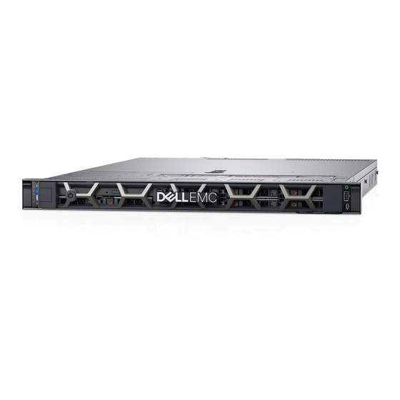
Dell EMC PowerEdge R440 overview The PowerEdge R440 is a 1U, dual socket rack system with 4 x 3.5 inch drives, 8 x 2.5 inch drives or 10 x 2.5 inch drives system and supports up to: • Two Intel Xeon Processor Scalable Family processors •... - Page 9 Contains the power button, USB port, iDRAC Direct micro port, and the iDRAC Direct status LED. Enable you to install drives that are supported on your system. For Drive slots more information about drives, see the Technical specifications section. Dell EMC PowerEdge R440 overview...
-
Page 10: Left Control Panel View
Kernel based Virtual Machine (KVM), on a supported mobile device. For more information, see the Integrated Dell Remote Access Controller User's Guide at Dell.com/idracmanuals. Status LED indicators NOTE: The indicators display solid amber if any error occurs. Dell EMC PowerEdge R440 overview... - Page 11 System health and system ID indicator codes The system health and system ID indicator is located on the left control panel of your system. Figure 6. System health and system ID indicators Dell EMC PowerEdge R440 overview...
- Page 12 If the problem persists, see the Getting help section. For more information, see Integrated Dell Remote Access Controller User's Guide at Dell.com/idracmanuals or Dell OpenManage Server Administrator User’s Guide at Dell.com/openmanagemanuals. Dell EMC PowerEdge R440 overview...
-
Page 13: Right Control Panel View
Direct port is actively connected to a device. For more information, see the iDRAC Direct LED indicator codessection. iDRAC Direct port (Micro-AB The iDRAC Direct (Micro-AB USB) USB) port enables you to access Dell EMC PowerEdge R440 overview... -
Page 14: Back View Of The System
Back view of the system The back view displays the features available on the back of the system. Figure 9. Back view of the system with full height riser Figure 10. Back view of the system with 2 risers Dell EMC PowerEdge R440 overview... - Page 15 Low profile riser right slot Use the card slot to connect half-height PCIe expansion card on low profile riser. For more information about the PSU configurations, see the Low profile riser left slot Technical Specifications section. Cabled PSU Dell EMC PowerEdge R440 overview...
-
Page 16: Drive Indicator Codes
Flashes amber four times per second Drive failed. Flashes green slowly Drive rebuilding. Solid green Drive online. Flashes green for three seconds, amber for three seconds, and Rebuild stopped. then turns off after six seconds Dell EMC PowerEdge R440 overview... -
Page 17: Nic Indicator Codes
AC power supply units (PSUs) have an illuminated translucent handle that serves as an indicator. The indicator shows whether power is present or if a power fault has occurred. Figure 13. AC PSU status indicator AC PSU status indicator/handle Dell EMC PowerEdge R440 overview... -
Page 18: Lcd Panel
If the LCD panel stops responding, remove the bezel and reinstall it. If the problem persists, see the Getting help section. • The LCD backlight remains off if LCD messaging is turned off using the iDRAC utility, the LCD panel, or other tools. Dell EMC PowerEdge R440 overview... -
Page 19: Viewing Home Screen
DNS entries are available. Set error Select SEL to view LCD error messages in a format that matches the IPMI description in the SEL. This enables you to match an LCD message with an SEL entry. Dell EMC PowerEdge R440 overview... -
Page 20: View Menu
Enterprise Service Tag (EST) is found on the back of the system. This information is used by Dell to route support calls to the appropriate personnel. Figure 15. Locating Service Tag of your system information tag (front view) information tag (back view) OpenManage Mobile (OMM) label iDRAC MAC address and iDRAC secure password label Service Tag Dell EMC PowerEdge R440 overview... -
Page 21: Documentation Resources
Dell OpenManage Essentials, see the Dell OpenManage Essentials User’s Guide. For information about installing and using Dell Dell.com/serviceabilitytools SupportAssist, see the Dell EMC SupportAssist Enterprise User’s Guide. For understanding the features of Dell Lifecycle Dell.com/idracmanuals Controller, see the Dell Lifecycle Controller User’s Guide. - Page 22 Task Document Location For information about partner programs enterprise Dell.com/openmanagemanuals systems management, see the OpenManage Connections Enterprise Systems Management documents. Working with the Dell For information about understanding the features Dell.com/storagecontrollermanuals PowerEdge RAID controllers of the Dell PowerEdge RAID controllers (PERC), Software RAID controllers, or BOSS card and deploying the cards, see the Storage controller documentation.
-
Page 23: Technical Specifications
Technical specifications The technical and environmental specifications of your system are outlined in this section. Topics: • System dimensions • Chassis weight • Processor specifications • PSU specifications • System battery specifications • Expansion bus specifications • Memory specifications • Storage controller specifications •... -
Page 24: System Dimensions
System dimensions Figure 16. Dimensions of the PowerEdge R440 system Table 14. Dimensions of the PowerEdge R440 system Za (with bezel) Za (without bezel) x4 and x10 = 482.0 mm (18.97 434.0 mm (17.08 42.8 mm (3.41 35.84 mm (1.41 22 mm (0.87... -
Page 25: Processor Specifications
The PowerEdge R440 system supports CR 2032 3.0-V lithium coin cell system battery. Expansion bus specifications The PowerEdge R440 system supports PCI express (PCIe) generation three expansion cards, which must be installed on the system board using expansion card risers. The R440 system supports three types of expansion card risers. -
Page 26: Storage Controller Specifications
One iDRAC Direct (Micro-AB USB) port NIC ports The PowerEdge R440 system supports two Network Interface Controller (NIC) ports on the back panel, which have two 1 Gbps configuration. NOTE: You can install up to five PCIe add-on NIC cards. -
Page 27: Serial Connector
9-pin connector, Data Terminal Equipment (DTE), 16550-compliant. VGA ports The Video Graphic Array (VGA) port enables you to connect the system to a VGA display. The PowerEdge R440 system supports two 15- pin VGA ports. Internal Dual SD Module The PowerEdge R440 system supports two optional flash memory card slots with an internal dual MicroSD module. -
Page 28: Particulate And Gaseous Contamination Specifications
Temperature Specifications Maximum temperature gradient (operating and storage) 20°C/h (68°F/h) Table 22. Relative humidity specifications Relative humidity Specifications Storage 5% to 95% RH with 33°C (91°F) maximum dew point. Atmosphere must be non-condensing at all times. Operating 10% to 80% relative humidity with 29°C (84.2°F) maximum dew point. Table 23. -
Page 29: Standard Operating Temperature
Table 27. Particulate contamination specifications Particulate contamination Specifications Air filtration Data center air filtration as defined by ISO Class 8 per ISO 14644-1 with a 95% upper confidence limit. NOTE: This condition applies to data center environments only. Air filtration requirements do not apply to IT equipment designed to be used outside a data center, in environments such as an office or factory floor. -
Page 30: Thermal Restriction Matrix
Expanded operating temperature Specifications NOTE: Outside the standard operating temperature (10°C to 40°C), the system can operate continuously in temperatures as low as 5°C and as high as 40°C. For temperatures between 35°C and 40°C, de-rate maximum allowable temperature by 1°C per 175 m above 950 m (1°F per 319 ft). ≤... - Page 31 Intel Xeon Platinum 8153 Intel Xeon Gold 6132 Intel Xeon Gold 6134 Intel Xeon Gold 6126 Intel Xeon Gold 6128 Intel Xeon Gold 5122 Intel Xeon Platinum 8156 Intel Xeon Gold 5120 Intel Xeon Gold 5118 Intel Xeon Gold 5115 Intel Xeon Silver 4116 Intel Xeon Silver...
-
Page 32: Initial System Setup And Configuration
Initial system setup and configuration Setting up your system Complete the following steps to set up your system: Unpack the system. Install the system into the rack. For more information about installing the system into the rack, see the Rail Installation Guide at Dell.com/poweredgemanuals. -
Page 33: Log In To Idrac
Interfaces Document/Section iDRAC Direct and See Dell Integrated Dell Remote Access Controller User's Guide at Dell.com/idracmanuals Quick Sync 2 (optional) NOTE: To access iDRAC, ensure that you connect the Ethernet cable to the iDRAC direct port. You can also access iDRAC through the shared LOM mode, if you have opted for a system that has the shared LOM mode enabled. -
Page 34: Downloading Drivers And Firmware
Table 33. Firmware and drivers Methods Location From the Dell Support site Dell.com/support/home Using Dell Remote Access Controller Lifecycle Controller (iDRAC Dell.com/idracmanuals with LC) Using Dell Repository Manager (DRM) Dell.com/openmanagemanuals Using Dell OpenManage Essentials (OME) Dell.com/openmanagemanuals Using Dell Server Update Utility (SUU) Dell.com/openmanagemanuals Using Dell OpenManage Deployment Toolkit (DTK) Dell.com/openmanagemanuals... -
Page 35: Pre-Operating System Management Applications
Pre-operating system management applications You can manage basic settings and features of a system without booting to the operating system by using the system firmware. Topics: • Options to manage the pre-operating system applications • System Setup • Dell Lifecycle Controller •... -
Page 36: Viewing System Setup
Viewing System Setup To view the System Setup screen, perform the following steps: Turn on, or restart your system. Press F2 immediately after you see the following message: F2 = System Setup NOTE: If your operating system begins to load before you press F2, wait for the system to finish booting, and then restart your system and try again. -
Page 37: System Bios
System BIOS You can use the System BIOS screen to edit specific functions such as boot order, system password, setup password, set the SATA and PCIe NVMeRAID mode, and enable or disable USB ports. Related links System BIOS Settings details System Information Memory Settings Processor Settings... -
Page 38: System Information
Option Description Boot Settings Specifies options to specify the Boot mode (BIOS or UEFI). Enables you to modify UEFI and BIOS boot settings. Network Settings Specifies options to manage the UEFI network settings and boot protocols. Legacy network settings are managed from the Device Settings menu. Integrated Devices Specifies options to manage integrated device controllers and ports, specifies related features and options. - Page 39 Option Description System Specifies the name of the system manufacturer. Manufacturer System Specifies the contact information of the system manufacturer. Manufacturer Contact Information System CPLD Specifies the current version of the system complex programmable logic device (CPLD) firmware. Version UEFI Compliance Specifies the UEFI compliance level of the system firmware.
- Page 40 Option Description Memory Operating Specifies the memory operating mode. The options available are Optimizer Mode, Single Rank Spare Mode, Multi Mode Rank Spare Mode, and Mirror Mode. This option is set to Optimizer Mode by default. NOTE: The Memory Operating Mode option can have different default and available options based on the memory configuration of your system.
-
Page 41: Processor Settings
Option Description NVDIMM-N Specifies information on the speed of the NVDIMM-N. Memory Speed NVDIMM-N Specifies information on the current firmware version on the NVDIMM-N. Memory Firmware version NVDIMM-N Specifies information on the serial number of the NVDIMM-N. Memory Serial Number NVDIMM-N Enables clearing data on specific NVDIMM-N and results in loss of data on that specific NVDIMM-N. - Page 42 Option Description For best performance, you should select Maximum data rate. Any reduction in the communication link frequency affects the performance of non-local memory accesses and cache coherency traffic. In addition, it can slow access to non-local I/O devices from a particular CPU. However, if power saving considerations outweigh performance, you might want to reduce the frequency of the CPU communication links.
- Page 43 Option Description Option Description Family-Model- Specifies the family, model, and stepping of the processor as defined by Intel. Stepping Brand Specifies the brand name. Level 2 Cache Specifies the total L2 cache. Level 3 Cache Specifies the total L3 cache. Number of Cores Specifies the number of cores per processor.
-
Page 44: Boot Settings
Option Description Option Description Capacity Specifies the total capacity of the drive. This field is undefined for removable media devices such as optical drives. Boot Settings You can use the Boot Settings screen to set the boot mode to either BIOS or UEFI. It also enables you to specify the boot order. •... - Page 45 Option Description attempted to boot. When this option is set to Enabled, all drives are attempted to boot in the order selected in the Hard-Disk Drive Sequence. This option is not enabled for UEFI Boot Mode. This option is set to Disabled by default.
-
Page 46: Network Settings
Network Settings You can use the Network Settings screen to modify UEFI PXE, iSCSI, and HTTP boot settings. The network settings option is available only in the UEFI mode. NOTE: The BIOS does not control network settings in the BIOS mode. For the BIOS boot mode, the optional Boot ROM of the network controllers handles the network settings. - Page 47 UEFI iSCSI Settings You can use the iSCSI Settings screen to modify iSCSI device settings. The iSCSI Settings option is available only in the UEFI boot mode. BIOS does not control network settings in the BIOS boot mode. For the BIOS boot mode, the option ROM of the network controller handles the network settings.
- Page 48 On the System BIOS screen, click Integrated Devices. Integrated Devices details The Integrated Devices screen details are explained as follows: Option Description User Accessible Configures the user accessible USB ports. Selecting Only Back Ports On disables the front USB ports; selecting USB Ports All Ports Off disables all front and back USB ports.
- Page 49 Option Description Internal microSD When Redundancy is set to Disabled, either one of the MicroSD card can be selected to present itself as mass Primary Card storage device by setting it to be primary card. By default primary MicroSD card is selected to be SD Card 1. If MicroSD Card 1 is not present, then the controller will select MicroSD Card 2 to be the primary MicroSD card.
- Page 50 Serial Communication You can use the Serial Communication screen to view the properties of the serial communication port. Viewing Serial Communication To view the Serial Communication screen, perform the following steps: Turn on, or restart your system. Press F2 immediately after you see the following message: F2 = System Setup NOTE: If your operating system begins to load before you press F2, wait for the system to finish booting, and then restart...
- Page 51 Option Description Redirection After Enables or disables the BIOS console redirection when the operating system is loaded. This option is set to Boot Enabled by default. System Profile Settings You can use the System Profile Settings screen to enable specific system performance settings such as power management. Viewing System Profile Settings To view the System Profile Settings screen, perform the following steps: Turn on, or restart your system.
-
Page 52: System Security
Option Description Memory Refresh Sets the memory refresh rate to either 1x or 2x. This option is set to 1x by default. Rate Uncore Frequency Enables you to select the Processor Uncore Frequency option. Dynamic mode enables the processor to optimize power resources across the cores and uncore during runtime. The optimization of the uncore frequency to either save power or optimize performance is influenced by the setting of the Energy Efficiency Policy option. - Page 53 System Security Settings details The System Security Settings screen details are explained as follows: Option Description Intel(R) AES-NI Improves the speed of applications by performing encryption and decryption by using the Advanced Encryption Standard Instruction Set (AES-NI). This option is set to Enabled by default. System Password Sets the system password.
-
Page 54: Options Description
Option Description Secure Boot Policy When Secure Boot policy is set to Standard, the BIOS uses the system manufacturer’s key and certificates to authenticate pre-boot images. When Secure Boot policy is set to Custom, the BIOS uses the user-defined key and certificates. -
Page 55: Using Your System Password To Secure Your System
Use the following guidelines to assign the system password: • A password can have up to 32 characters. • The password can contain the numbers 0 through 9. • Only the following special characters are allowed: space, (”), (+), (,), (-), (.), (/), (;), ([), (\), (]), (`). A message prompts you to reenter the system password. - Page 56 Operating with setup password enabled If Setup Password is set to Enabled, type the correct setup password before modifying the system setup options. If you do not type the correct password in three attempts, the system displays the following message: Invalid Password! Number of unsuccessful password attempts: <x>...
-
Page 57: Miscellaneous Settings
Option Description NOTE: RAID configurations and NVMe cards not are included as BIOS does not have the ability to distinguish between individual drives in those configurations. Redundant OS NOTE: This option is disabled if Redundant OS Location is set to None. State When set to Visible, the backup disk is visible to the boot list and OS. -
Page 58: Idrac Settings Utility
Option Description Load Legacy Video Enables you to determine whether the system BIOS loads the legacy video (INT 10H) option ROM from the video Option ROM controller. Selecting Enabled in the operating system does not support UEFI video output standards. This field is available only for UEFI boot mode. -
Page 59: Boot Manager
Boot Manager The Boot Manager screen enables you to select boot options and diagnostic utilities. Related links Boot Manager main menu System BIOS Viewing Boot Manager Viewing Boot Manager About this task To enter Boot Manager: Steps Turn on, or restart your system. Enter the result of your step here (optional). -
Page 60: System Utilities
System Utilities System Utilities contains the following utilities that can be launched: • Launch Diagnostics • BIOS Update File Explorer • Reboot System Related links Boot Manager PXE boot You can use the Preboot Execution Environment (PXE) option to boot and configure the networked systems, remotely. To access the PXE boot option, boot the system and then press F12 during POST instead of using standard Boot Sequence from BIOS Setup. -
Page 61: Installing And Removing System Components
Installing and removing system components Safety instructions WARNING: Whenever you need to lift the system, get others to assist you. To avoid injury, do not attempt to lift the system by yourself. WARNING: Opening or removing the system cover while the system is powered on may expose you to a risk of electric shock. CAUTION: Do not operate the system without the cover for a duration exceeding five minutes. -
Page 62: Optional Front Bezel
• Phillips #2 screwdriver • Torx #T30 screwdriver • Torx #T8 screwdriver • Wrist grounding strap Optional front bezel An optional metal bezel is mounted on the front of the system to display system branding. A lock on the bezel is used to protect unauthorized access to the drives. -
Page 63: Installing The Front Bezel
Installing the front bezel The procedure to install the front bezel with and without the LCD panel is the same. Prerequisite Follow the safety guidelines listed in Safety instructions. Steps Locate and remove the bezel key. NOTE: The bezel key is part of the LCD bezel package. Align and insert the tabs on the bezel into the slots on the system. -
Page 64: Installing The System Cover
Figure 19. Removing the system cover Related links Installing the system cover Installing the system cover Prerequisites Follow the safety guidelines listed in Safety instructions. Ensure that all internal cables are routed correctly and connected, and no tools or extra parts are left inside the system. Steps Align the tabs on the system cover with the guide slots on the system. -
Page 65: Inside The System
Figure 20. Installing the system cover Next steps Reconnect the peripherals and connect the system to the electrical outlet. Turn on the system, including any attached peripherals. Inside the system CAUTION: Many repairs may only be done by a certified service technician. You should only perform troubleshooting and simple repairs as authorized in your product documentation, or as directed by the online or telephone service and support team. -
Page 66: Backplane Cover
Figure 21. Inside the system left control panel cable cover hard drive backplane backplane expander board cabling latch air shroud intrusion switch power interposer board internal expansion riser low profile expansion riser 1 low profile expansion riser 2 processor blank heat sink air shroud cooling fan blank... -
Page 67: Installing The Backplane Cover
Figure 22. Removing backplane cover Related links Installing the backplane cover Installing the backplane cover Prerequisites Follow the safety guidelines listed in Safety instructions. Follow the procedure listed in Before working inside your system. Install the system cover. Steps Align the tabs on the backplane cover with the guide slots on the system. Slide the backplane cover toward the front of the system until the cover locks into place. -
Page 68: Air Shroud
Figure 23. Installing backplane cover Next step Follow the procedure listed in After working inside your system. Air shroud The air shroud directs the airflow across the entire system. Air shroud prevents the system from overheating and is used to maintain uniform airflow inside the system. -
Page 69: Installing The Air Shroud
Figure 24. Removing the air shroud Next steps If applicable, install the air shroud. Follow the procedure listed in After working inside your system. Related links Removing an expansion card riser Installing the air shroud Installing the air shroud Prerequisites Follow the safety guidelines listed in Safety instructions. -
Page 70: Cooling Fans
Figure 25. Installing the air shroud Next step Follow the procedure listed in After working inside your system. Cooling fans The cooling fans are integrated into the system to dissipate the heat generated by the functioning of the system. These fans provide cooling for the processors, expansion cards, and memory modules. -
Page 71: Installing Cooling Fan
NOTE: Ensure that you note the routing of the cables as you remove them from the system board. Figure 26. Removing the cooling fan Lift the fan out holding the blue touch point. Next steps Install the cooling fan. Install the internal riser. Connect the power cable to the system board. -
Page 72: Intrusion Switch
Move the cables out of the way to access the cooling fan cable connector on the system board. Steps Holding the blue touch point, place the cooling fan into the cooling fan cage. Route the cooling fan cable and connect it to the connector on the system board. Figure 27. -
Page 73: Removing The Intrusion Switch
Removing the intrusion switch Prerequisites Follow the safety guidelines listed in Safety instructions. Follow the procedure listed in Before working inside your system. Remove air shroud. Remove internal PERC riser. Steps Disconnect the intrusion switch cable connected to the system board. NOTE: Ensure that you note the routing of the cables as you remove them from the system board. -
Page 74: Drives
Figure 29. Installing intrusion switch Slide the intrusion switch until it is firmly seated in the intrusion switch slot. Connect the intrusion switch cable to the connector on the system board. Next steps Install internal PERC riser. Follow the procedure listed in After working inside your system. -
Page 75: Installing A Drive Blank
Figure 30. Removing a drive blank Next step Install a drive or a drive blank. Related links Installing a drive blank Installing a drive blank The procedure for installing 2.5 inch and 3.5 inch drive blanks is identical. Prerequisites Follow the safety guidelines listed in Safety instructions. -
Page 76: Removing A 2.5 Inch Drive From A 3.5 Inch Drive Adapter
Removing a 2.5 inch drive from a 3.5 inch drive adapter Prerequisites Follow the safety guidelines listed in Safety instructions. Remove the 3.5 inch drive adapter from the 3.5 inch drive carrier. NOTE: A 2.5 inch drive is installed in a 3.5 inch drive adapter, which is then installed in the 3.5 inch drive carrier. Steps Using a Phillips #2 screwdriver, remove the screws from the side of the 3.5 inch drive adapter. -
Page 77: Removing A 3.5 Inch Drive Adapter From A 3.5 Inch Drive Carrier
Steps Align the screw holes on the 2.5 inch drive with the screw holes on the 3.5 inch drive adapter. Using a Phillips #2 screwdriver, secure the 2.5 inch drive to the 3.5 inch drive adapter. Figure 33. Installing a 2.5 inch drive into a 3.5 inch drive adapter Removing a 3.5 inch drive adapter from a 3.5 inch drive carrier Prerequisites Follow the safety guidelines listed in... -
Page 78: Installing A 3.5 Inch Drive Adapter Into The 3.5 Inch Drive Carrier
Figure 34. Removing a 3.5 inch drive adapter from a 3.5 inch drive carrier Next step Install the 3.5 inch drive carrier or install the 3.5 inch drive adapter into the 3.5 inch drive carrier. Installing a 3.5 inch drive adapter into the 3.5 inch drive carrier Prerequisites Follow the safety guidelines listed in Safety... -
Page 79: Removing A Hard Drive
Figure 35. Installing a 3.5 inch drive adapter into the 3.5 inch drive carrier Next steps Install the 3.5 inch drive carrier into the system. If removed, install the front bezel. Removing a hard drive Prerequisites Follow the safety guidelines listed in Safety instructions. -
Page 80: Installing A Hard Drive
Figure 36. Removing a hard drive Next steps Install a hard drive. If you are not replacing the hard drive immediately, insert a hard drive blank in the empty hard drive slot to maintain proper system cooling. Installing a hard drive Prerequisites CAUTION: Before attempting to remove or install a hard drive while the system is running, see the documentation for the storage... -
Page 81: Removing The Drive From The Drive Carrier
Figure 37. Installing a hard drive Next step If applicable, install the front bezel. Removing the drive from the drive carrier Prerequisite CAUTION: Mixing drives from previous generations of PowerEdge servers is not supported. Steps Using a Phillips #1 screwdriver, remove the screws from the slide rails on the drive carrier. Lift the drive out of the drive carrier. -
Page 82: Installing A Drive Into The Drive Carrier
Figure 38. Removing the drive from the drive carrier Next step If applicable, install the drive into the drive carrier. Related links Installing a drive into the drive carrier Installing a drive into the drive carrier Prerequisites CAUTION: Mixing drive carriers from other generations of PowerEdge servers is not supported. NOTE: When installing a drive into the drive carrier, ensure that the screws are torqued to 4 in-lbs. -
Page 83: System Memory
Figure 39. Installing a drive into the drive carrier System memory The system supports DDR4 registered DIMMs (RDIMMs) and load reduced DIMMs (LRDIMMs). System memory holds the instructions that are executed by the processor. NOTE: MT/s indicates DIMM speed in MegaTransfers per second. Memory bus operating frequency can be 1866 MT/s, 2133 MT/s, 2400 MT/s, or 2666 MT/s depending on the following factors: •... -
Page 84: Removing A Memory Module
Removing a memory module Prerequisites Follow the safety guidelines listed in Safety instructions. Follow the procedure listed in Before working inside your system. If applicable, remove the air shroud. WARNING: Allow the memory modules to cool after you power off the system. Handle the memory modules by the card edges and avoid touching the components or metallic contacts on the memory module. -
Page 85: Processors And Heat Sinks
CAUTION: To prevent damage to the memory module or the memory module socket during installation, do not bend or flex the memory module. You must insert both ends of the memory module simultaneously. Open the ejectors on the memory module socket outward to allow the memory module to be inserted into the socket. Align the edge connector of the memory module with the alignment key of the memory module socket, and insert the memory module in the socket. -
Page 86: Removing A Processor And Heat Sink Module
Removing a processor and heat sink module Prerequisites WARNING: The heat sink may be hot to touch for some time after the system is powered down. Allow the heat sink to cool before removing it. Follow the safety guidelines listed in Safety instructions. -
Page 87: Removing The Processor From The Processor And Heat Sink Module
Removing the processor from the processor and heat sink module Prerequisites NOTE: Only remove the processor from the processor and heat sink module if you are replacing the processor or heat sink. This procedure is not required when replacing a system board. Follow the safety guidelines listed in Safety instructions. -
Page 88: Installing The Processor Into A Processor And Heat Sink Module
Figure 44. Removing the processor bracket Next step Install the processor into the processor and heat sink module. Related links Removing the air shroud Removing a processor and heat sink module Installing the processor into a processor and heat sink module Installing the processor into a processor and heat sink module Prerequisite Follow the safety guidelines listed in... - Page 89 Figure 45. Installing the processor bracket If you are using an existing heat sink, remove the thermal grease from the heat sink by using a clean lint-free cloth. Use the thermal grease syringe included with your processor kit to apply the grease in a quadrilateral design on the top of the processor.
-
Page 90: Installing A Processor And Heat Sink Module
Place the heat sink on the processor and push down on the base of the heat sink until the bracket locks onto the heat sink. NOTE: • Ensure that the two guide pin holes on the bracket match the guide holes on the heat sink. •... - Page 91 Steps Align the pin 1 indicator of the heat sink to the system board and then place the processor and heat sink module (PHM) on the processor socket. CAUTION: To avoid damaging the fins on the heat sink, do not press down on the heat sink fins.
-
Page 92: Internal Perc Riser
Follow the procedure listed in After working inside your system. Internal PERC riser The internal PERC riser has Harpoon-based Premium Performance tier offering that drives IOPs and enhanced SSD performance. Removing the internal PERC riser Prerequisites Follow the safety guidelines listed in Safety instructions. -
Page 93: Installing The Internal Perc Riser
Figure 50. Disconnecting the cable from internal PERC card Next steps Install the air shroud. Follow the procedure listed in After working inside your system. Install the internal PERC card. Related links Removing the air shroud Installing the internal PERC riser Installing the internal PERC riser Prerequisite Follow the safety guidelines listed in... - Page 94 Figure 51. Connecting the cable to internal PERC riser Holding the blue touch points, align the slot on the internal PERC riser to the guide on the system board. Insert the internal riser card’s edge connector firmly into the system board connector until the riser is fully seated. Lift the plunger to lock the riser in place.
-
Page 95: Removing The Perc Card From The Internal Perc Riser
Removing the PERC card from the internal PERC riser Prerequisites Follow the safety guidelines listed in Safety instructions. Follow the procedure listed in Before working inside your system. Remove the Air shroud. Remove the internal PERC riser. Steps Using a Phillips #2 screwdriver, remove the screw that secures the PERC card to the internal PERC riser. Pull the PERC card out of the connector on the internal PERC riser. -
Page 96: Installing Perc Card Into The Internal Perc Riser
Installing PERC card into the internal PERC riser Prerequisite Follow the safety guidelines listed in Safety instructions. Steps Insert the PERC card into the internal PERC riser and push the card in. Using a Phillips #2 screwdriver, replace the screw to secure the PERC card on the internal PERC riser. Figure 54. -
Page 97: Expansion Bus Specifications
Expansion bus specifications The PowerEdge R440 system supports PCI express (PCIe) generation 3 expansion cards, which are installed on the system, using expansion card risers. This system supports 1A, 2A, 1B, and 2B expansion card risers. Expansion card installation guidelines Depending on your system configuration, the following PCI Express (PCIe) generation 3 expansion cards are supported: Table 38. - Page 98 Card Type Slot Priority Form Factor FC16 HBA (Emulex) Low Profile 10Gb NICs (Broadcom) Low Profile 10Gb NICs (Intel) Low Profile 10Gb NICs (Mellanox) Low Profile 10Gb NICs (QLogic) Low Profile 10Gb NICs (Solarflare) Low Profile FC8 HBA (Emulex) Low Profile FC8 HBA (QLogic) Low Profile 1Gb NICs (Broadcom)
- Page 99 Card type Slot priority Form factor FC16 HBA (Emulex) 1, 2, 3 Low Profile 10Gb NICs (Broadcom) 1, 2, 3 Low Profile 10Gb NICs (Intel) 1, 2, 3 Low Profile 10Gb NICs (Mellanox) 1, 2, 3 Low Profile 10Gb NICs (QLogic) 1, 2, 3 Low Profile 10Gb NICs (Solarflare)
- Page 100 Card type Slot priority Form factor 10Gb NICs (Intel) Low Profile 10Gb NICs (Mellanox) Low Profile 10Gb NICs (QLogic) Low Profile 10Gb NICs (Solarflare) Low Profile FC8 HBA (Emulex) Low Profile FC8 HBA (QLogic) Low Profile 1Gb NICs (Broadcom) Low Profile 1Gb NICs (Intel) Low Profile Adapter RAID (Dell design)
- Page 101 Card type Slot priority Form factor Integrated RAID (Dell design) Integrated Slot NONE rNDC (Broadcom) Integrated Slot NONE rNDC (Intel) Integrated Slot NONE rNDC (Mellanox) Integrated Slot NONE rNDC (QLogic) Integrated Slot NONE Table 42. Riser configurations:1A Card type Slot priority Form factor Adapter RAID (Dell design) Low Profile...
-
Page 102: Removing An Expansion Card Riser
Card type Slot priority Form factor rNDC (Broadcom) Integrated Slot NONE rNDC (Intel) Integrated Slot NONE rNDC (Mellanox) Integrated Slot NONE rNDC (QLogic) Integrated Slot NONE Removing an expansion card riser Prerequisites Follow the safety guidelines listed in Safety instructions. Follow the procedure listed in Before working inside your system. -
Page 103: Installing An Expansion Card Riser
Figure 56. Removing an expansion card riser 1 Figure 57. Removing an expansion card riser 2 Next step Install the expansion card riser. Installing an expansion card riser Prerequisite Follow the safety guidelines listed in Safety instructions. Installing and removing system components... - Page 104 Steps If removed, install the expansion cards into the expansion card riser. Holding the touch points, align the slot on the riser with the guide in the system board. Lower the expansion card riser into place until the expansion card riser connector is fully seated in the connector. Figure 58.
-
Page 105: Removing The Expansion Card From The Expansion Card Riser
Figure 60. Installing an expansion card riser 2 Next steps Follow the procedure listed in After working inside your system. Install any device drivers required for the card as described in the documentation for the card. Removing the expansion card from the expansion card riser Prerequisites Follow the safety guidelines listed in Safety... - Page 106 Figure 61. Removing expansion card from riser 2 Figure 62. Removing expansion card from riser 1 Install a filler bracket if you are not replacing the expansion card. NOTE: You must install a filler bracket over an empty expansion card slot to maintain Federal Communications Commission (FCC) certification of the system.
- Page 107 Figure 63. Installing filler bracket for riser 2 Figure 64. Installing filler bracket for riser 1 Next step Install expansion card into the expansion card riser. Installing and removing system components...
-
Page 108: Installing The Expansion Card Into The Expansion Card Riser
Installing the expansion card into the expansion card riser Prerequisites Follow the safety guidelines listed in Safety instructions. If installing a new expansion card, unpack it and prepare the card for installation. NOTE: For instructions, see the documentation accompanying the card. Remove the expansion card riser. - Page 109 Figure 66. Removing filler bracket for riser 1 Hold the card by its edges, and align the card edge connector with the expansion card connector on the riser. Insert the card edge connector firmly into the expansion card connector until the card is fully seated. Close the expansion card latch.
-
Page 110: M.2 Ssd Module
Figure 68. Installing expansion card into riser 1 Next steps If applicable, connect the cables to the expansion card. Install the expansion card riser If applicable, install the air shroud. Follow the procedure listed in After working inside your system. Install any device drivers required for the card as described in the documentation for the card. -
Page 111: Installing The M.2 Ssd Module
Figure 69. Removing the M.2 SSD module module connector (2) screws (2) module (2) Next step Install the M.2 SSD module. Installing the M.2 SSD module Prerequisite Follow the safety guidelines listed in Safety instructions. Steps Align the M.2 SSD module connectors with the connectors on the BOSS card. Push the M.2 SSD module until the module is seated firmly on the BOSS card. -
Page 112: Optional Idsdm Or Vflash Module
Figure 70. Installing the M.2 SSD module module connector (2) screws (2) modules (2) Next steps Install the BOSS card. NOTE: Installing the BOSS card is similar to installing the expansion card riser. Install the air shroud. Follow the procedure listed in After working inside your system. -
Page 113: Installing The Microsd Card
Next steps Follow the procedure listed in After working inside your system. Install a MicroSD card. Related links Installing the MicroSD card Installing the MicroSD card Prerequisites Follow the safety guidelines listed in Safety instructions. NOTE: To use an MicroSD card with your system, ensure that the Internal SD Card Port is enabled in System Setup. NOTE: If reinstalling, ensure that you install the MicroSD cards into the same slots based on the labels you had marked on the cards during removal. -
Page 114: Installing Optional Idsdm Or Vflash Card
Figure 71. Removing the optional IDSDM/vFlash card NOTE: There are two dip switches on the IDSDM/vFlash card for write-protection. Next step Install the optional IDSDM/vFlash card. Related links Installing optional IDSDM or vFlash card Installing optional IDSDM or vFlash card Prerequisite Follow the safety guidelines listed in Safety... -
Page 115: Lom Riser Card
Figure 72. Installing optional IDSDM/vFlash card Next steps Install the MicroSD cards. NOTE: Reinstall the MicroSD cards into the same slots based on the labels you had marked on the cards during removal. Follow the procedure listed in After working inside your system. -
Page 116: Installing The Lom Riser Card
Figure 73. Removing LOM riser card Next step Install the LOM riser card. Installing the LOM riser card Prerequisite Follow the safety guidelines listed in Safety instructions. Steps Align the connectors on the LOM riser card with the slot on the system. Press the LOM riser card until the card is firmly seated on the system board connector and the two blue plastic snap hold the LOM riser card in place. -
Page 117: Hard Drive Backplane
Follow the procedure listed in After working inside your system. Hard drive backplane Depending on your system configuration, the hard drive backplanes supported in PowerEdge R440 are listed here: Table 43. Supported backplane options for PowerEdge R440 systems System Supported hard drives options 3.5 inch (x4) SAS, SATA backplane... -
Page 118: Removing The Hard Drive Backplane
Figure 78. 10 x 2.5 backplane with expander SAS_A connector backplane signal cable connector backplane power cable connector SAS_B connector SAS_C connector Removing the hard drive backplane Prerequisites CAUTION: To prevent damage to the drives and backplane, remove the hard drives from the system before removing the backplane. -
Page 119: Installing The Hard Drive Backplane
Figure 79. Removing the hard drive backplane Lift the backplane out of the system. Next step Install the hard drive backplane. Installing the hard drive backplane Prerequisite Follow the safety guidelines listed in Safety instructions. NOTE: The procedure to install the backplane is similar for all backplane configurations. Steps Align the slots on the backplane with the hooks on the system. - Page 120 Figure 80. Installing the hard drive backplane Next steps Connect all the cables to the backplane. Install all the hard drives. Install the backplane cover. Install the air shroud. Follow the procedure listed in After working inside your system. Installing and removing system components...
-
Page 121: Cable Routing
Cable routing Figure 81. Cable routing - 10 x 2.5 hard drive backplane with PERC backplane backplane expander backplane power cable backplane signal cable backplane expander signal cable cable routing clip power interposer board internal riser system board SAS cable (BP: SAS_B to internal riser) SAS cable (BP: SAS_A to internal riser) Installing and removing system components... - Page 122 Figure 82. Cable routing - 10 x 2.5 hard drive backplane with NVMe backplane backplane expander backplane power cable backplane power cable backplane expander signal cable cable routing clip power interposer board expansion card riser system board internal riser SAS cable (BP: SAS_B to expansion card riser) SAS cable (BP: SAS_A to expansion card riser) NVMe cable connector (BP: PCIe to internal riser) NVMe cable connector (BP: PCIe to MB)
- Page 123 Figure 83. Cable routing - 8 x 2.5 hard drive backplane with PERC hard drive backplane backplane power cable SAS cable (SAS_B connector to internal riser) SAS cable (SAS_A connector to internal riser) backplane signal cable cable routing clip power interposer board internal riser system board Installing and removing system components...
- Page 124 Figure 84. Cable routing - 8 x 2.5 hard drive backplane with onboard SATA hard drive backplane backplane power cable SATA cable (BP: SATA_B to MB) SATA cable (BP: SATA_A to MB) backplane signal cable cable routing clip power interposer board system board Installing and removing system components...
- Page 125 Figure 85. Cable routing - 4 x 3.5 hard drive backplane with PERC hard drive backplane backplane signal cable cable routing clip SAS cable (BP: SAS_A to PERC) backplane power cable power supply unit system board Installing and removing system components...
-
Page 126: System Battery
Figure 86. Cable routing - 4 x 3.5 hard drive backplane with SATA hard drive backplane backplane signal cable cable routing clip SATA cable (BP: SATA_A to MB) backplane power cable power supply unit system board System battery The system battery is used for low-level system functions such as powering the real-time and date settings of the system. Replacing the system battery Prerequisites WARNING:... -
Page 127: Optional Internal Usb Memory Key
CAUTION: To avoid damage to the battery connector, you must firmly support the connector while installing or removing a battery. Use a plastic scribe to pry out the system battery. Figure 87. Removing the system battery To install a new system battery, hold the battery with the positive side facing up and slide it under the securing tabs. Press the battery into the connector until it snaps into place. -
Page 128: Replacing The Optional Internal Usb Memory Key
Replacing the optional internal USB memory key Prerequisites CAUTION: To avoid interference with other components in the server, the maximum permissible dimensions of the USB memory key are 15.9 mm wide x 57.15 mm long x 7.9 mm high. Follow the safety guidelines listed in Safety instructions. -
Page 129: Installing The Optical Drive
Figure 89. Removing optical drive Next step Install an optical drive. Installing the optical drive Prerequisite Follow the safety guidelines listed in Safety instructions. Steps Align the optical drive with the optical drive slot on the front of the system. Slide in the optical drive until the release tab snaps into place. -
Page 130: Power Supply Units
Next step Follow the procedure listed in After working inside your system. Power supply units The power supply unit (PSU) is an internal hardware component which supplies power to the components in the system. Your system supports one of the following: •... -
Page 131: Installing A Power Supply Unit Blank
Related links Installing a power supply unit Installing a power supply unit blank Installing a power supply unit blank Prerequisite Follow the safety guidelines listed in Safety instructions. NOTE: Install the power supply unit (PSU) blank only in the second PSU bay. Step Align the PSU blank with the PSU slot and push it into the PSU slot until it clicks into place. -
Page 132: Installing A Power Supply Unit
Figure 93. Removing a power supply unit Next step Install the PSU. Related links Installing a power supply unit Installing a power supply unit Prerequisites Follow the safety guidelines listed in Safety instructions. For systems that support redundant PSU, ensure that both the PSUs are of the same type and have the same maximum output power. -
Page 133: Removing A Non-Redundant Cabled Ac Power Supply Unit
Figure 94. Installing a power supply unit Next steps If you have unlatched the cable management arm, relatch it. For information about the cable management arm, see the system’s rack documentation at Dell.com/poweredgemanuals. Connect the power cable to the PSU, and plug the cable into a power outlet. CAUTION: When connecting the power cable to the PSU, secure the cable to the PSU with the strap. -
Page 134: Installing A Non-Redundant Cabled Ac Power Supply Unit
Figure 95. Removing non-redundant cabled AC PSU Next step Installing a non-redundant cabled AC power supply. Related links Removing the air shroud Removing an expansion card riser Installing a non-redundant cabled AC power supply unit Installing a non-redundant cabled AC power supply unit Prerequisite Follow the safety guidelines listed in Safety... -
Page 135: Power Interposer Board
If applicable, install the expansion card riser. Install the air shroud. Follow the procedure listed in After working inside your system. Power interposer board The power interposer board (PIB) is a board that connects the hot swappable power supply units (PSUs) to the system board. The PIB is only supported in systems with redundant PSUs. -
Page 136: Installing Power Interposer Board
Installing power interposer board Prerequisite Follow the safety guidelines listed in Safety instructions. Steps Align the slots on the PIB with the guides on the system. Using a Phillips #2 screwdriver, replace the two screws to secure the PIB to the system. Route the cables and connect it to the system board. - Page 137 Follow the procedure listed in Before working inside your system. Remove the air shroud. Remove the internal PERC riser. Steps Disconnect the control panel cable from the system board connector. NOTE: Ensure that you note the routing of the cables as you remove them from the system board. You must route the cables properly when you replace them to prevent the cables from being pinched or crimped.
-
Page 138: Installing The Left Control Panel
Installing the left control panel Prerequisite Follow the safety guidelines listed in Safety instructions. Steps Route the control panel cable through the side wall of the system. Align the left control panel assembly with the control panel slot on the system and place the assembly in the slot on the system. Connect the control panel cable to the system board connector. -
Page 139: Installing The Right Control Panel
Figure 102. Removing the cable cover Using a Phillips #1 screwdriver, remove the screw that secures the control panel to the system. Figure 103. Removing right control panel Holding the control panel by its sides, remove the control panel away from the system. Next step Install the right control panel. - Page 140 Steps Route the control panel cable through the system. Align the right control panel with the control panel slot on the system and place the assembly in the slot on the system. Connect the control panel cable to the connector on the system board and lower the cable latch to secure the cable in place. Using a Phillips #1 screwdriver, install the screw that secures the control panel to the system.
-
Page 141: System Board
System board A system board (also known as the motherboard) is the main printed circuit board in the system with different connectors used to connect different components or peripherals of the system. A system board provides the electrical connections to the components in the system to communicate. -
Page 142: Installing The System Board
Figure 106. Removing the system board Next step Install the system board. Installing the system board Prerequisite Follow the safety guidelines listed in Safety instructions. Steps Unpack the new system board assembly. CAUTION: Do not lift the system board by holding a memory module, processor, or other components. CAUTION: Take care not to damage the system identification button while placing the system board into the chassis. - Page 143 Figure 107. Installing the system board Next steps Replace the following: Trusted Platform Module (TPM) Internal PERC riser Internal USB key (if applicable) USB 3.0 module (if applicable) IDSDM/vFlash module card All expansion cards and risers Processors and heat sink modules Processors blanks (if applicable) Memory modules and memory module blanks LOM riser card...
-
Page 144: Restoring The Service Tag Using Easy Restore
Restoring the Service Tag using Easy Restore The easy restore feature allows you to restore your service tag, license, UEFI configuration, and the system configuration data after replacing the system board. All data is backed up in a backup flash device automatically. If BIOS detects a new system board, and the service tag in the backup flash device, BIOS prompts the user to restore the backup information. -
Page 145: Trusted Platform Module
Trusted Platform Module Trusted Platform Module (TPM) is a dedicated microprocessor designed to secure hardware by integrating cryptographic keys into devices. Software can use a TPM to authenticate hardware devices. Because each TPM chip has a unique and secret RSA key which is embedded during the manufacture of the TPM, it is capable of performing platform authentication operation. -
Page 146: Initializing Tpm For Bitlocker Users
Figure 108. Installing the TPM Next steps Install the system board. Follow the procedure listed in After working inside your system. Initializing TPM for BitLocker users Initialize the TPM. For more information, see http://technet.microsoft.com/en-us/library/cc753140.aspx. The TPM Status changes to Enabled, Activated. Initializing the TPM 1.2 for TXT users While booting your system, press F2 to enter System Setup. -
Page 147: Using System Diagnostics
Using system diagnostics If you experience a problem with your system, run the system diagnostics before contacting Dell for technical assistance. The purpose of running system diagnostics is to test your system hardware without using additional equipment or risking data loss. If you are unable to fix the problem yourself, service and support personnel can use the diagnostics results to help you solve the problem. -
Page 148: System Diagnostic Controls
System diagnostic controls Menu Description Configuration Displays the configuration and status information of all detected devices. Results Displays the results of all tests that are run. System health Provides the current overview of the system performance. Event log Displays a time-stamped log of the results of all tests run on the system. This is displayed if at least one event description is recorded. -
Page 149: Jumpers And Connectors
Jumpers and connectors This topic provides specific information about the jumpers. It also provides some basic information about jumpers and switches and describes the connectors on the board in the system. Jumpers on the system board help to disable the system and setup passwords. You must know the connectors on the system board to install components and cables correctly. -
Page 150: System Board Jumpers And Connectors
System board jumpers and connectors Figure 109. System board jumpers and connectors Table 44. System board jumpers and connectors Item Connector Description FAN6 Cooling fan 6 connector CPU1 Processor socket 1 CPU1_PWR_CONN(P2) CPU1 power connector J_INTRU Intrusion switch connector J_BP_SIG1 Backplane signal connector 1 LFT_CP_CONN Left control panel connector... -
Page 151: System Board Jumper Settings
Item Connector Description RGT_CP_CONN Right panel connector SYS_PWR_CONN(P1) System power connector J_PIB_SIG1 Power interposer board signal connector 1 J_PIB_SIG2 Power interposer board signal connector 2 J_ACE Internal Dual SD Module J_CP_USB2 Front USB connector J_SATA_A1 Internal SATA A connector J_SATA_C1 Internal SATA C connector PCIE_G3_X8(CPU1) Internal PERC controller connector... -
Page 152: Disabling Forgotten Password
Table 45. System board jumper settings Jumper Setting Description PWRD_EN The BIOS password feature is enabled. The BIOS password feature is disabled. iDRAC local access is unlocked at next AC power cycle. iDRAC password reset is enabled in F2 iDRAC settings menu. NVRAM_CLR The BIOS configuration settings are retained at system boot. -
Page 153: Getting Help
The Contact Technical Support page is displayed with details to call, chat, or e-mail the Dell Global Technical Support team. Documentation feedback You can rate the documentation or write your feedback on any of our Dell EMC documentation pages and click Send Feedback to send your feedback. - Page 154 Use your smartphone or tablet to scan the model-specific Quick Resource (QR) code on your Dell PowerEdge system or in the Quick Resource Locator section. Quick Resource Locator for PowerEdge R440 Figure 110. Quick Resource Locator Receiving automated support with SupportAssist Dell SupportAssist is an optional Dell Services offering that automates technical support for your Dell server, storage, and networking devices.
Need help?
Do you have a question about the PowerEdge R440 and is the answer not in the manual?
Questions and answers