Samsung SCX-4500 Service Manual
Digital laser printer slim size 3 in 1 mfp
Hide thumbs
Also See for SCX-4500:
- User manual (96 pages) ,
- Manual del usuario (97 pages) ,
- Specifications (12 pages)
Table of Contents
Advertisement
Quick Links
SERVICE
DIGITAL LASER PRINT
SCX-4500
SCX-4500
SCX-4500/XAZ
Basic Model : SCX-4500
Manual
The keynote of Product
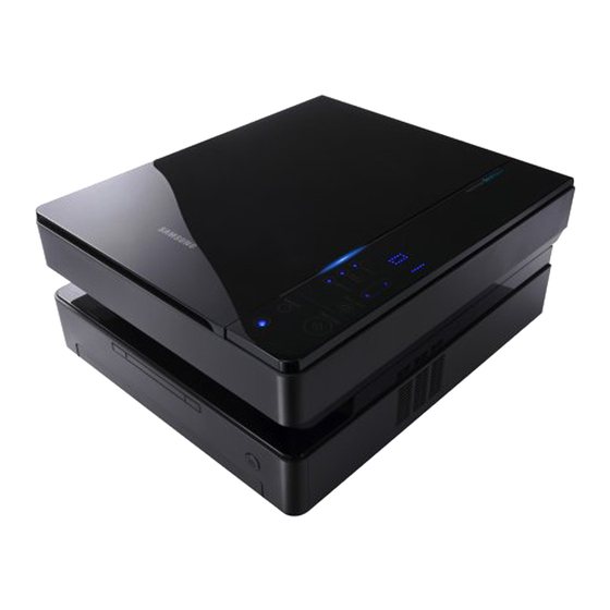
Slim Size 3 in 1 MFP (SCX-4500)
- Printing Speed : 16PPM(A4), 17PPM(Ltr)
- Printing Resolution : 600 x 600dpi
- Interface : USB 2.0
- OPE : Touch Sensor
- Scanner : FLAT-BED CIS(600dpi)
- Scan Resolution(Optiacl) : 600 x 2,400dpi
- Paper Input Capacity : 100 sheets
- Paper Output Capacity : 30 sheets
- Engine Life : 50,000 Pages
- Toner : Initial(1K) / Sales(2K)
Advertisement
Table of Contents
Troubleshooting

Related Manuals for Samsung SCX-4500


Summary of Contents for Samsung SCX-4500
- Page 1 Basic Model : SCX-4500 SERVICE Manual DIGITAL LASER PRINT The keynote of Product Slim Size 3 in 1 MFP (SCX-4500) - Printing Speed : 16PPM(A4), 17PPM(Ltr) - Printing Resolution : 600 x 600dpi - Interface : USB 2.0 - OPE : Touch Sensor...
-
Page 2: Table Of Contents
Contents 1. Precautions 1.1 Safety Warning 1.2 Caution for safety 1.3 ESD Precautions 2. Product specification and feature 2.1 Product Specifications 2.1.1 Product Overview 2.1.2 Specifications 2.1.3 Model Comparison Table 2.1.4 ACCESSORY 2.2 Summary of Product 2.2.1 Printer Components 2.2.2 System Layout 2-16 2.2.3 System Description 2-17... - Page 3 Continued 3.10 Fuser Unit 3-16 3.11 Transfer Roller 3-17 4. Adjustment and Troubleshooting 4.1 Alignment and Adjustments 4.1.1 Control Panel 4.1.2 Status of OP Panel 4.1.3 Manu Map 4-12 4.1.4 Report Printing Condition 4-21 4.1.5 Table. Periodic Images according to Rollers 4-21 4.1.6 Paper Path and Jam Error Solution 4-22...
- Page 4 Continued 5.9 Cassette 5-20 6. System Diagram 6.1 Block Diagram 6.2 Connection Diagram 7. Reference information 7.1 Tool for Troubleshooting 7.2 Acronyms and Abbreviations 7.3 Select a location for the printer 7.4 Sample Tests Patterns 7.5 Parts Life Cycle Maintenance Table 7.5.1 Parts Life Cycle Maintenance Table 7.5.2 Toner Cartridge Criterion 7.6 Model Information...
-
Page 5: Precautions
High voltages and lasers inside this product are dangerous. This printer should only be serviced by a suitably trained and qualified service engineer. (2) Use only Samsung replacement parts There are no user serviceable parts inside the printer. Do not make any unauthorized changes or additions to the printer, these could cause the printer to malfunction and create electric shock or fire hazards. -
Page 6: Caution For Safety
Take care not to cut or damage the power cable or plugs when moving the machine. (9) Use caution during thunder or lightening storms. Samsung recommends that this machine be disconnected from the power source when such weather conditions are expected. Do not touch the machine or the power cord if it is still connected to the wall socket in these weather conditions. -
Page 7: Handling Precautions
1.2.4 Assembly / Disassembly Precautions Replace parts carefully, always use Samsung parts. Take care to note the exact location of parts and also cable routing before dismantling any part of the machine. Ensure all parts and cables are replaced correctly. -
Page 8: Disregarding This Warning May Cause Bodily Injury
Failure to do so could cause the printer to tip or fall possibly causing personal injury or damaging the printer. (5) Do not install the printer on a sloping or unstable surface. After installation, double check that the printer is stable. Service Manual Samsung Electronics... -
Page 9: Esd Precautions
9. Minimize bodily motions when handling unpackaged replacement ESDs. Normal motions, such as the brushing together of clothing fabric and lifting one’s foot from a carpeted floor, can generate static electricity sufficient to damage an ESD. Service Manual Samsung Electronics... -
Page 10: Product Specification And Feature
- 256 levels gray scale - Up to 600 x 600 dpi 2.1.2 Specifications Product Specifications are subject to change without notice. See below for product specifications. 2.1.2.1 General Spec. SPEC. SCX-4500 SIZE(WxDxH) 332*393*164.5mm BOX SIZE(WxDxH) 421*553*261mm NOISE WARMING UP... - Page 11 Transfer Roller : 50K Pages Print Fuser : 50K Pages Print Product Life Toner Cartridge Life initial : 1000 Pages (ISO 19752 Standard Pattern) High Yield : 2000 Pages Duty cycle Monthly print volume : Up to 4000 pages Service Manual Samsung Electronics...
- Page 12 Toner Save 2) PC Interface Item Specification and Description No cable included (Note : SEC will NOT supply any of interface cable.) Minimum PC Spec Pentium2 400Mhz 64MB RAM Hard Disk : 300 free disk space Service Manual Samsung Electronics...
- Page 13 Lineart/Halftone : 15 sec / Gray : 30 sec / Color : 75 sec Gray Scale 256 Levels Effective Scanning Width 208 mm(8.2 inches) Effective Scanning Length PLATEN 297 mm(11.7 inches) Scan To E-mail, Image, OCR, WEB <= SmarThru IV Service Manual Samsung Electronics...
- Page 14 5) Accessory Item Specification and Description Quick Set-Up guide Owners Manual Yes, 1CD User guide Bundle s/w SmarThru 4 Toner Cartridge 1 EA Drum Unit Power Cable In Out Guide Printer Cable USB Cable No(Except Korea) Service Manual Samsung Electronics...
-
Page 15: Model Comparison Table
Product specification and feature 2.1.3 Model Comparison Table Model (SEC) Laser MFP SCX-4500 Laser Printer ML-1630 General Size (W*D*H) 332*393*164.5mm 332*375.6*121.5mm Input Capacity 100 sheets Output Capacity 30 sheets Engine Life 50,000 sheets Toner 2K (Initial 1K) Interface USB 2.0... - Page 16 Product specification and feature Competitor Model Samsung Brother SCX-4500 DCP-7020 LJ-1005 General Size (W*D*H) 332*393*164.5mm 432*395*294mm 437*363*308mm Input Capacity 100 sheets 250 sheets 150 sheets Output Capacity 30 sheets 100sheets 100 sheets Engine Life 50,000 sheets Toner 2K (Initial 1K) 2.5K(drum 12K)
-
Page 17: Accessory
3903-000042 USB Cable JC39-00001A Driver-CD JC46-00348A MANUAL-(CARD)WARRANTY CARD JC68-00690A MANUAL-SERVICE CARD JC68-00421A 1 COVER PAPER ACCESSORY BAG 2 POWER CORD 3 USB Cable 4 Driver-CD 5 MANUAL-(CARD)WARRANTY CARD 6 MANUAL-SERVICE CARD KRA1JC99-02061D C100X8C0028 SCX-4500/XEV ED:?? 3903-000042 Service Manual Samsung Electronics... -
Page 18: Summary Of Product
This chapter describes the functions and operating principal of the main component. 2.2.1 Printer Components 2.2.1.1 Front View control panel tray open button scanner lid scanner glass top cover top cover lever output tray print cartridge output support inner cover tray Service Manual Samsung Electronics... - Page 19 Product specification and feature 2.2.1.2 Rear View rear cover power receptacle power switch USB port Service Manual 2-10 Samsung Electronics...
- Page 20 Feeding Capacity : Cassette 100 Sheets(75g/ , 20lb Paper Standard) Cassette 1 Sheet(Paper, OHP, etc.) Paper Detecting Sensor : Photo Sensor Paper Size Sensor : N/A 2.2.1.2(b) Transfer Ass'y Life Span : Print over 50,000 Sheets(in 15~30 ) Transfer roller Service Manual 2-11 Samsung Electronics...
- Page 21 2.2.1.2(c) Driver Ass'y By driving the motor, it supplies power to the feeding unit, the fusing unit, and the distributing unit. In SCX-4500 Series, Latch Gear is used for an easy Jam Removal at Gear Drv Fuser 2.2.1.2(d) Fuser Ass'y...
- Page 22 The life span of toner : 2,000 Sheets(ISO 19752 Standard) OPC Cleaning : Collect the toner by using cleanning blade Management of disused toner : Collect the toner by using electric static (Non-Cleaner type) OPC Drum protecting Shutter : None Service Manual 2-13 Samsung Electronics...
- Page 23 Maximum Scan Width : 216 mm (width of Letter Size) Effective Scan Length : 297 mm Scan Line Time : 1.5 msec(mono) TIMING BELT MOTOR ASS'Y COVER - SCAN LOWER SLIDER - CIS SHAFT CIS COVER PANEL Service Manual 2-14 Samsung Electronics...
- Page 24 Product specification and feature Panel Main (Status) Display Copies Main LED Light Error LED Light Copy Setting Button Reduce/ Silk Screen Silk Screen Enlarge Guide description Darkness Stop/Clear Cancel Button Start/Copy Scan to PC Command Button Power Button Service Manual 2-15 Samsung Electronics...
-
Page 25: System Layout
Product specification and feature 2.2.2 System Layout Service Manual 2-16 Samsung Electronics... -
Page 26: System Description
Product specification and feature 2.2.3 System Description SCX-4500 is made up of Main Controller and Operation Panel, Scan/Copy Part, SMPS/HVPS part and Engine Part. Main Controller uses Chorus2 for its ASIC, which is on chip micro controller and is composed of 1Mbyte Flash memory and 8Mbyte SDRAM to control 16Bit Bus. -
Page 27: Main Controller
Product specification and feature 2.2.3.2 Main Controller SCX-4500 is consisted of ASIC(CPU), scan part and print part and Bus Control. I/O Handling, scan part, each driver, and PC interface are working controlled by the CPU. Main Controller has full capability on Main Board. There are 2 major functions in the CPU which are Controller ASIC and Image Processor. - Page 28 Product specification and feature 2.2.3.3 SCAN Part SCX-4500 has color scanning functionality and Chorus II and Scan Part is consisted of Signal Controller and Scan Motor Controller. - Resolution : 600x2400dpi(MAX) - Effective Scanning Length : 216mm - Effective picture elements : 5104(600DPI), 2552(300DPI) - Sensor elements : 5136 dots 2.2.3.4 Motor Contorllor...
- Page 29 Main Board is consist of Engine and Controller on the one-Board. Main board interfaces PC and communicates with Image Scan and LCD of OPE Panel. Video data comes out from LSU. it senses and controls motor driving, Fuser high voltage, and sensors. Service Manual 2-20 Samsung Electronics...
- Page 30 Input Current : Under 4.0Arms / 2.5Arms (But, the status when lamp is off or rated voltage is inputted/outputted ) Main < - > SMPS Connector Heat Lamp1, 2 Connector Paper Feed Sensor AC Input Connector Service Manual 2-21 Samsung Electronics...
- Page 31 Charge Voltage (MHV) - Input Voltage : 24 V DC - Out Voltage : -1.2KV ~ -1.8KV DC - Out Voltage Rising Time : 50 ms Max - Out Voltage Falling Time : 50 ms Max Service Manual 2-22 Samsung Electronics...
-
Page 32: Paper Exit Sensor
- 100 V Connector - 1300 V HVPS board supply high voltage for developing Process. - 730 V High Voltage controlled by PWM signal from CPU. - 430 V Paper Exit Sensor exists on HVPS. +1,300 V Service Manual 2-23 Samsung Electronics... - Page 33 Triac, the Triac becomes off, and then the heat lamp is turned off. - Triac feature :16A, 600V SWITCHING - Phototriac Coupler Service Manual 2-24 Samsung Electronics...
-
Page 34: S/W Descriptions
Host. 2. Kernel that control and management the whole procedure include of Control flow and Printing Job before transfer to Engine system. Service Manual 2-25 Samsung Electronics... - Page 35 4. Port Monitor that manages the network communication between spooler and Network Interface Card, or various addi- tional application and Network Interface Card,(this is, at first, make communication logical port, manage the data, transfer them from spooler to network port, and offer the result of printing). Service Manual 2-26 Samsung Electronics...
- Page 36 Engine print the received data to required paper with the sequential developing process. The additional printing function are realized in (1) Web environment (2) Window environment. On addition, Kernel informs a status of printing status and printer status to user made printing job with the Status Monitor. Service Manual 2-27 Samsung Electronics...
-
Page 37: General Precautions On Disassembly
3. Unplug the power cord. 4. Use a flat and clean surface. 5. Replace only with authorized components. 6. Do not force plastic-material components. 7. Make sure all components are in their proper position. Service Manual Samsung Electronics... -
Page 38: Cover Unit
1-1. If necessary, remove the SPRING-ETC of ROLLER-IDLE and take out the GUIDE-FEED- LOWER from the MEA UNIT-FEED LOWER. ROLLER -IDLE 1. Take out the MEA UNIT-FEED LOWER. 2. To remove COVER-REAR, first remove the three screws. Service Manual Samsung Electronics... - Page 39 4. Take out the Toner Cartridge. 7. Following 6. procedure, unlatch the rear latch of the COVER-LEFT. 5. To Remove the COVER-FUSER DUMMY, remove the two screws and then release the COVER-FUSER DUMMY. 8. Release the COVER-LEFT. Service Manual Samsung Electronics...
- Page 40 (Cassette disassembly is referred to Chapter 3.4 in 13. In the same way, remove the hinge in the left side of detail.) the COVER-FRONT. 11. To remove the COVER- FRONT, first remove the 14. Release the COVER-FRONT. two screws. Service Manual Samsung Electronics...
-
Page 41: Cassette
2. Release the GUIDE-CASSETTE LOCK from both side of the CASSETTE. 6. Overturn the CASSETTE, and remove the one screw from PINION GEAR. 3. Release the RING CS (2EA) from the GUIDE-CAS- SETTE LOCK 7. Release the GUIDE-SIDE-L.R. 4. Release the GUIDE-REAR. Service Manual Samsung Electronics... - Page 42 10. Spin and Release the SPRING CS from the PLATE- KNOCKUP. 14. Release the SRING ETC-LOCKER PLATE from the both left and right side of the FRAME CST. 11. Release the SHAFT-P-CORE from the PLATE- KNOCKUP. Service Manual Samsung Electronics...
-
Page 43: Scanner Unit
4. Lift up the Scanner Unit with left hand, and release the top of the LINK UPPER with right hand. 2. Release the COVER SCAN REAR of the Scanner Unit. 5. Remove the one screw , as shown below. 3. Remove the two screws. Service Manual Samsung Electronics... - Page 44 7. Release the Scanner Unit from the SET. by using a tool. 8. To release the COVER SCAN OPE of the ELA UNIT- SCAN OPE, follow below procedure (9~12) LOCKING 7 POINT LOCKING 7 POINT LOCKING 7 POINT LOCKING 7 POINT Service Manual Samsung Electronics...
- Page 45 15. Push up the ELA UNIT-CIS to the direction of the OPE. arrow. Bottom Bottom 16. Release the TIMMING GEAR, as shown below. 13. To remove the COVER SCAN OPE of the ELA UNIT-SCAN OPE, remove the Harness OPE from the COVER SCAN OPE. Service Manual Samsung Electronics...
- Page 46 17. Remove the HARNESS-CIS-FFC from the ELA 19. Release the PULLY IDLE. UNIT-CIS. HARNESS -CIS-FFC 20. To remove the ELA UNIT-SCAN DRIVE, remove the 18. Remove the SHAFT CIS. three screws and release it with the connected cable. Service Manual 3-10 Samsung Electronics...
-
Page 47: Lsu Unit
1. To remove the ELA UNIT LSU from the ELA UNIT- FRAME UPPER, remove 4 screws that is under the 3. Release the the ELA UNIT LSU from the ELA UNIT- WHITE-SHEET-SPONGE. First remove 2 screws to FRAME UPPER. the left side. Service Manual 3-11 Samsung Electronics... -
Page 48: Drive Unit
2. Remove the six screws and pull the ELA UNIT DRIVE to the direction of arrow. 1. To remove the ELA UNIT DRIVE, remove the two screws of the LINK-RAIL UPPER and release it. 3. Remove the HARNESS-MOTOR from the ELA UNIT DRIVE. Service Manual 3-12 Samsung Electronics... -
Page 49: Main Board
Disassembly and Reassembly 3.7 Main Board 2. Remove the 4 screws, and release the Main Board from the SET. 1. Unplug the Harness, as shown below. Service Manual 3-13 Samsung Electronics... -
Page 50: Hvps Board
1. To remove the HVPS Board, remove the 4 screws 3. Remove the HARNESS-HVPS from the HVPS and release the COVER HVPS. Board, as shown below. 2. Turn the HVPS Board to the direction of the arrow. HVPS Board Service Manual 3-14 Samsung Electronics... -
Page 51: Smps Board
1. To release the SMPS Board, first remove the 8 4. Remove the 2 screw. screws. 5. IF necessary, release the SMPS Board from the 2. Lift up the SMPS Board as shown the below. SHIELD-SMPS. SHIELD-SMPS Service Manual 3-15 Samsung Electronics... -
Page 52: Fuser Unit
Disassembly and Reassembly 3.10 Fuser Unit 2. To release the ELA HOU-FUSER from the SET, remove the 4 screws. 1. Lift up and turn the FRAME UPPER. 3. Release the ELA HOU-FUSER. Service Manual 3-16 Samsung Electronics... -
Page 53: Transfer Roller
Disassembly and Reassembly 3.11 Transfer Roller 2. Release the Transfer Roller from the SET. 1. Lift up the Transfer Roller. Service Manual 3-17 Samsung Electronics... -
Page 54: Adjustment And Troubleshooting
Blinks when the paper in the tray is empty. toner LED Blinks when the print cartridge is almost empty or is not Samsung- genuine cartridge. If it blinks rapidly, the print cartridge is totally empty. Check the display message and replace the print cartridge. -
Page 55: Status Of Op Panel
Install Error Moving Down Arrow head One twinking light per 2 sec Toner Exhausted (On: 1 Sec + Off: 1 Sec) Non Samsung Toner User Mode Invalid Toner Option Unit Interface Error One twinking light per 2 sec Recovable Error... - Page 56 Adjustment and Troubleshooting OPE Design Service Manual Samsung Electronics...
- Page 57 Adjustment and Troubleshooting Main LED TEXT Definition Service Manual Samsung Electronics...
- Page 58 Adjustment and Troubleshooting Function and Indication Description Service Manual Samsung Electronics...
- Page 59 Adjustment and Troubleshooting Function and Indication Description Service Manual Samsung Electronics...
- Page 60 Adjustment and Troubleshooting LED Display Interaction Service Manual Samsung Electronics...
- Page 61 Adjustment and Troubleshooting LED Display Interaction Service Manual Samsung Electronics...
- Page 62 Adjustment and Troubleshooting LED Display Interaction Service Manual Samsung Electronics...
- Page 63 Adjustment and Troubleshooting LED Display Interaction Service Manual 4-10 Samsung Electronics...
- Page 64 Do not everything togling information when multi-error happened and main-display marks prierity unfirma- tion and gives response in under error icons. When produce error during printing, printing and error status need togling that show intersection. Service Manual 4-11 Samsung Electronics...
-
Page 65: Manu Map
Factory Mode A A4 - Aging testA4 A LT - Aging testLT A 01 - Aging test2 A 02 A 02 - Aging test2 A 03- Aging test3 A 04- Aging test4 A 03 A 04 Service Manual 4-12 Samsung Electronics... -
Page 66: Status Led
This led will glow if there is paper Empty condition. Toner Status This Led will glow if there is Toner error condition Paper Jam Status This led will glow if there is paper Jam condition. Service Manual 4-13 Samsung Electronics... - Page 67 • Press Power --> Copies --> ScanTO to go to Data Setup Menu. Following Menu would be displayed after pressing Power --> Copies --> ScanTO key sequence. [DS - Data [M - Machine [RP - Report Setup] Test] Print] [RP - Report [M - Machine [DS - Data Print] Test] Setup] Service Manual 4-14 Samsung Electronics...
- Page 68 Adjustment and Troubleshooting Service Manual 4-15 Samsung Electronics...
- Page 69 Adjustment and Troubleshooting Service Manual 4-16 Samsung Electronics...
- Page 70 Adjustment and Troubleshooting Service Manual 4-17 Samsung Electronics...
- Page 71 Adjustment and Troubleshooting Service Manual 4-18 Samsung Electronics...
- Page 72 Adjustment and Troubleshooting Service Manual 4-19 Samsung Electronics...
-
Page 73: System Data List
Adjustment and Troubleshooting 4.1.3.3 System Data List Service Manual 4-20 Samsung Electronics... -
Page 74: Report Printing Condition
35.2 mm White Spot, Horizontal black band Transfer Roller 47.1 mm Periodic Band (by little difference of density) Heat Roller 77.09 mm Black Spot and Image Ghost Pressure Roller 75.36 mm Black Spot on Enter Blackside Service Manual 4-21 Samsung Electronics... -
Page 75: Paper Path And Jam Error Solution
Always pull firmly and evenly; do not jerk the paper. if the paper lears, ensure that all fragments of paper are removed; otherwise a jam will occur again. 4.1.6.1 Paper Path Service Manual 4-22 Samsung Electronics... -
Page 76: Clearing Paper Jams
1. Press the tray open button. 3. Remove the jammed paper by gently pulling it straight out as shown below. 2. Pull the tray open. 4. Align the tray with the slot, and slide it into the machine. Service Manual 4-23 Samsung Electronics... - Page 77 6. Hold the top cover and close it slowly and carefully, until the cover is securely latched. 11. Open and close the top cover firmly. The machine will resume printing. 7. If the paper LED blinks, go to next step. 8. Open the rear cover. Service Manual 4-24 Samsung Electronics...
- Page 78 3. Hold both edges of the rear cover, and align it as shown in the following figure. Press the rear cover firmly until it clicks. 6. If the paper LED blinks, go to next step. 7. Press the top cover lever, completely open the top cover. Service Manual 4-25 Samsung Electronics...
- Page 79 11. Slide the print cartridge back into the machine. 9. Carefully take the jammed paper out of the machine. 12. Close the top cover firmly. The machine will resume printing. Service Manual 4-26 Samsung Electronics...
- Page 80 4. Open the inner cover. 2. If a long portion of the paper is visible, pull it straight out. inner cover If there is any resistance removing the paper, stop pulling Service Manual 4-27 Samsung Electronics...
- Page 81 6. Close the inner cover. machine. 7. After removing the jammed paper, check for paper which may be jammed in other parts of the machine. 8. Close the top cover firmly. The machine will resume printing. Service Manual 4-28 Samsung Electronics...
-
Page 82: Error Messages
LED blinks rapidly The print cartridge which the arrow Replace the corresponding print cartridge indicates has run out. with a Samsung-genuine cartridge. The print cartridge is installed improperly, Reinstall the print cartridge two or three or not installed. times. If the problem persists, the print LED blinks rapidly cartridge is not being detected. -
Page 83: Troubleshooting
OP Panel - Main PBA error - Display Panel error Refer to Indicate Ready or Error Display Error Display Power save <Chapter 4.1.7> Test Print printing Refer to "Solution Quality is of Image Problem" Nomal? Service Manual 4-30 Samsung Electronics... -
Page 84: The Cause And Solution Of Image Quality
4.2.2.1 Vertical Black Line and Band Description: 1. Straight thin black vertical lines occur in the prnting 2. Dark black vertical bands occurrs in the printing Digital Printer Digital Printer Digital Printer Digital Printer Digital Printer Service Manual 4-31 Samsung Electronics... - Page 85 Adjustment and Troubleshooting 4.2.2.2 Vertical White Line Description: White vertical voids in the image. Digital Printer Digital Printer Digital Printer Digital Printer Digital Printer Service Manual 4-32 Samsung Electronics...
- Page 86 Digital Printer Digital Printer Digital Printer Digital Printer Digital Printer 1) OPC Drum = 62.8mm 2) Charge Roller = 26.7mm 3) Supply Roller = 46.9mm 4) Developing Roller = 35.2mm 5) Transfer Roller = 47.1mm Service Manual 4-33 Samsung Electronics...
- Page 87 4.2.2.4 Black/White Spot Description: 1. Dark or blurry spots occur periodically in the printing 2. White spots occur periodically in the printing Digital Printer Digital Printer Digital Printer Digital Printer Digital Printer 26.7 62.8 62.8 62.8 26.7 Service Manual 4-34 Samsung Electronics...
- Page 88 Adjustment and Troubleshooting 4.2.2.5 Light Image Description: The printed image is light, with no ghost. Digital Printer Digital Printer Digital Printer Digital Printer Digital Printer Service Manual 4-35 Samsung Electronics...
- Page 89 Adjustment and Troubleshooting 4.2.2.6 Dark image or Black Description: The printed image is dark. Digital Printer Digital Printer Digital Printer Digital Printer Digital Printer Service Manual 4-36 Samsung Electronics...
-
Page 90: Uneven Density
Adjustment and Troubleshooting 4.2.2.7 Uneven Density Description: Print Density is uneven between left and right. Service Manual 4-37 Samsung Electronics... - Page 91 Adjustment and Troubleshooting 4.2.2.8 Background Description:Light dark background appears in whole area of the printing. Digital Printer Digital Printer Digital Printer Digital Printer Digital Printer Service Manual 4-38 Samsung Electronics...
- Page 92 Adjustment and Troubleshooting 4.2.2.9 Ghost(1) Description: Ghost occur at 63mm intervals of the OPC drum in the whole Printing Digital Printer Digital Printer Digital Printer Digital Printer Digital Printer Digital Printer Service Manual 4-39 Samsung Electronics...
- Page 93 Adjustment and Troubleshooting 4.2.2.10 Strain in the Face of the Page Description: The background on the face of the printed page strained. Digital Printer Digital Printer Digital Printer Digital Printer Digital Printer Service Manual 4-40 Samsung Electronics...
- Page 94 Adjustment and Troubleshooting 4.2.2.11 Strains on Back of Page Description: The back of the page is strained at 47.1 or 75.36 mm intervals. Digital Digital Pri Digital Printer Digital Printer Digital Printer 75.36 Service Manual 4-41 Samsung Electronics...
- Page 95 Adjustment and Troubleshooting 4.2.2.12 Blank Page Print out(1) Description: Blank page is printed. Digital Printer Digital Printer Digital Printer Digital Printer Digital Printer Service Manual 4-42 Samsung Electronics...
-
Page 96: The Cause And Solution Of The Paper Feeding
Adjustment and Troubleshooting 4.2.3 The cause and solution of the paper feeding 4.2.3.1 Wrong Print Position Description: Printing begins at wrong position on the paper. Service Manual 4-43 Samsung Electronics... - Page 97 Adjustment and Troubleshooting 4.2.3.2 JAM 0 Description: 1. Paper does not exit from the cassette. 2. Jam-0 occurs when the paper feeds into the printer Service Manual 4-44 Samsung Electronics...
- Page 98 Adjustment and Troubleshooting 4.2.3.3 JAM 1 Description: 1. Paper is jammed in front of or inside the fuser. 2. Paper is stuck in the exit roller and in the fuser just after passing through the Actuator-Feed Service Manual 4-45 Samsung Electronics...
- Page 99 4.2.3.4 JAM 2 Description: 1. Recording paper is jammed in front of or inside the fuser. 2. Recording paper is stuck in the discharge roller and in the fuser just after passing through the Actuator-Feed. Service Manual 4-46 Samsung Electronics...
- Page 100 Adjustment and Troubleshooting 4.2.3.5 Multi-Feeding Description: Multiple sheets of paper are fed at once. Service Manual 4-47 Samsung Electronics...
-
Page 101: Paper Rolled In The Fuser
Adjustment and Troubleshooting 4.2.3.6 Paper rolled in the fuser Description: Paper rolled around fuser rollers or ‘Concertina’ jam Service Manual 4-48 Samsung Electronics... -
Page 102: Copy Problems
1. Check the Scanner Motor and gear. and there are no foreign objects in the mechanism or scanner path. Replace any worn parts. 2. Check the Motor Driver on Driver PBA. Replace the main PBA. Service Manual 4-49 Samsung Electronics... - Page 103 A gap of more than 0.5mm can cause 2. Check the gap between a blurred image. Ensure rollers and original and scanner glass. cover close correctly. Replace as necessary. See "Print" troubleshooting. 3. Check printing quality. Service Manual 4-50 Samsung Electronics...
- Page 104 2. Paper has a rough suface texture. Use paper with a smother suface finish. Can the friction pad rubber with a soft cloth dampened with IPA (lsopropyl 3. Friction Pad is contaminated. Alcohol) or water. Service Manual 4-51 Samsung Electronics...
-
Page 105: The Cause And Solution Of The Malfunction
Adjustment and Troubleshooting 4.2.5 The cause and solution of the malfunction 4.2.5.1 Fuser Error Description : message (Fuser High Error / Fuser Low Error / Fuser Open Error) is displayed on a smart panel. Service Manual 4-52 Samsung Electronics... - Page 106 Adjustment and Troubleshooting 4.2.5.2 LSU Unit Error Description : message LSU Error / LSU Hsyne Error is displayed on a smart panel. Service Manual 4-53 Samsung Electronics...
- Page 107 Adjustment and Troubleshooting 4.2.5.3 Paper Empty Error Description : The paper lamp on the operator panel is on even when paper is loaded in the cassette. Service Manual 4-54 Samsung Electronics...
-
Page 108: Cover Open Error
Adjustment and Troubleshooting 4.2.5.4 Cover open Error Description : message “Cover open” is displayed on a smart panel. Service Manual 4-55 Samsung Electronics... - Page 109 Adjustment and Troubleshooting 4.2.5.5 No power Error Description : When system power is turned on, all lamps on the operator panel do not come on. Service Manual 4-56 Samsung Electronics...
-
Page 110: Exploded Views & Parts List
5.5 Frame Upper 5-10 DIGITAL LASER PRINT The keynote of Product Slim Size 3 in 1 MFP (SCX-4500) - Printing Speed : 16PPM(A4), 17PPM(Ltr) - Printing Resolution : 600 x 600dpi - Interface : USB 2.0 - OPE : Touch Sensor... -
Page 111: Main
Exploded Views & Parts List 5.1 Main Service Manual Samsung Electronics... - Page 112 Exploded Views & Parts List Main Parts List Drawer# SEC_CODE DESCRIPTION QT’Y Service Remark 5.1-0 SCX-4500 5.1-1 JC96-04645A ELA UNIT-FRAME LOWER 5.1-2 JC66-01564A LINK-UPPER 5.1-3 JC61-02178A STUD-HINGE 5.1-4 6031-001602 WASHER-PLAIN 5.1-8 JC66-01218A ROLLER-TRANSFER 5.1-10 JC92-01891A PBA-MAIN 5.1-11 JC97-02978A MEA UNIT-COVER LOWER 5.1-12...
-
Page 113: Scanner Unit
Exploded Views & Parts List 5.2 Scanner Unit Service Manual Samsung Electronics... - Page 114 JC39-00680A HANESS-OPE 5.2-8 JC97-02930A MEA UNIT-SCAN UPPER 5.2-9 JB01-00002A CLASS-PLATEN 5.2-10 JB68-00644A LASER_SHADING 5.2-11 0203-001841 TAPE-DOUBLE FACE 5.2-12 JC64-00317A WINDOW-INDICATOR 5.2-13 JC96-04533C ELA-UNIT-SCAN OPE 5.2-14 JC63-013333A COVER SCAN PLATEN 5.2-15 JC63-00209A SHEETUNIT SPONGE 5.2-16 3301-001742 CORE-FERRITE Service Manual Samsung Electronics...
-
Page 115: Ope Unit
Exploded Views & Parts List 5.3 OPE Unit Service Manual Samsung Electronics... - Page 116 Exploded Views & Parts List OPE Unit Parts List Drawer# SEC_Code Description QT'y Service Remark 5.3-0 JC96-04533A ELA UNIT-SCAN OPE 5.3-1 JC63-01333A COVER-SCAN OPE 5.3-2 JC63-01468A SHEET-SCAN DIFUSSION 5.3-3 JC61-02008A HOLDER LED MAIN 5.3-4 0203-002250 TAPE-DOUBLE FACE 5.3-5 JC92-01892A PBA-OPE Service Manual Samsung Electronics...
-
Page 117: Cover Lower
Exploded Views & Parts List 5.4 Cover Lower Service Manual Samsung Electronics... - Page 118 Service Remark 5.4-0 JC97-02978A MEA UNIT-COVER LOWER 5.4-1 JC63-01383A COVER LEFT 5.4-2 JC63-01384A COVER RIGHT 5.4-3 JC63-01436A COVER REAR 5.4-4 JC97-03055A MEA UNIT-COVER FRONT 5.4-4-1 JC63-01382A COVER-FRONT 5.4-4-2 JC61-00060A SPRING ETC-TS BLADE 5.4-4-3 JC63-01434A COVER DOOR STAKER Service Manual Samsung Electronics...
-
Page 119: Frame Upper
Exploded Views & Parts List 5.5 Frame Upper Service Manual 5-10 Samsung Electronics... - Page 120 5.5-6 6003-000282 SCREW-TAPTITE 5.5-7 JC61-70958A SPRING ETC-GUIDE TR 5.5-8 JC61-02108A PLATE GUIDE DEVE 5.5-9 JC61-70932A SPRING ETC-GUIDE DEVE 5.5-10 JC66-01545A LEVEL HANDLE UPPER 5.5-11 JC62-00417A SEAL-LSU 5.5-12 JC63-01444A COVER DUMMY EXTRA 5.5-13 JC62-00464A SEAL-LSU REAR Service Manual 5-11 Samsung Electronics...
-
Page 121: Frame Lower
Exploded Views & Parts List 5.6 Frame Lower 1 Service Manual 5-12 Samsung Electronics... - Page 122 Exploded Views & Parts List Frame Lower 2 Service Manual 5-13 Samsung Electronics...
- Page 123 MEA UNIT-ROLLER PICKUP 5.6-40-1 JC61-00909A HOUSING-M-PICK UP_R2 5.6-40-2 JC61-02079A HOUSING-PICKUP B 5.6-40-3 JC72-01231A SPONGE-ROLLER PICK_UP 5.6-41 JC97-02957A MEA UNIT-GEAR PICKUP 5.6-42 JC63-01414A GROUND DRIVE 5.6-43 0604-001095 PHOTO INTERRUTER 5.6-44 JC66-01541A ATUATOR EMPTY 5.6-45 6107-001164 SPRING TS Service Manual 5-14 Samsung Electronics...
- Page 124 JC61-40001A FOOT-ML 80 5.6-67 JC61-02110A GUIDE-CASETTE RAIL 5.6-69 JC31-00089A FAN-DC_HAWK 5.6-70 JC39-00737A HARNESS-FUSER 5.6-71 JC39-00697A HARNESS-MAIN 5.6-72 JC63-01421A SHIELD-MAIN 5.6-73 JC61-70940A SPRING ETC-TR(12) 5.6-74 JC61-00588A BUSH-M-TRL 5.6-75 JC72-00102A PMO-BUSHING_TR(L) 5.6-76 JC72-01418A SPONGE-LEFT 5.6-77 JC72-01419A SPONGE-RIGHT Service Manual 5-15 Samsung Electronics...
-
Page 125: Main Drive
Exploded Views & Parts List 5.7 Main Drive Service Manual 5-16 Samsung Electronics... - Page 126 5.7-9 JC66-01440A GEAR DRV OPC 5.7-10 JC66-01443A GEAR DRIVE PICK UP 5.7-11 JC66-01447A GEAR RDCN FEED B 5.7-12 JC66-01446A GEAR RDCN FEED A 5.7-13 JC66-01442A GEAR DRV REGI 5.7-14 6001-000130 SCREW MACHINE 5.7-15 6031-001602 WHASHER-PLAIN Service Manual 5-17 Samsung Electronics...
-
Page 127: Fuser
Exploded Views & Parts List 5.8 Fuser Service Manual 5-18 Samsung Electronics... -
Page 128: Fuser Parts List
RUBBER-EXIT F/UP 5.8-27 JC66-01312B ROLLER-IDLE 5.8-28 JC70-00064A IPR-PIN ROLLER EXIT 5.8-29 JC72-20902B PEX-ROLLER F/UP(2) 5.8-30 6107-001347 SPRING-ETC 5.8-31 JC61-02129A GUIDE-EXIT 5.8-32 JC61-02012A HOLDER-LAMP 5.8-33 JC67-00111A CAP-M_ACTUATOR_UP 5.8-34 6107-001346 SPRING-CS 5.8-35 JC63-01446A COVER-LAMP 5.8-36 JC63-01739A FELT-FUSER Service Manual 5-19 Samsung Electronics... -
Page 129: Cassette
Exploded Views & Parts List 5.9 Cassette Service Manual 5-20 Samsung Electronics... - Page 130 6003-000264 SCREW-TAPTITE 5.9-9 JC61-02124A GUIDE-SIDE L 5.9-10 JC61-02125A GUIDE-SIDE R 5.9-11 JG61-70531A SPRING ETC-LOCKER,PLATE 5.9-12 JC61-02128A GUIDE-KNOCKUP R 5.9-13 JC61-02127A GUIDE-KNOCKUP L 5.9-14 6107-001349 SPRING-CS 5.9-15 JC61-02080A PLATE-KNOCKUP 5.9-16 JC73-00141A RPR-PAD CASSETTE 5.9-17 JC66-00720A SHAFT-P-CORE Service Manual 5-21 Samsung Electronics...
-
Page 131: System Diagram
System Diagram 6. System Diagram 6.1 Block Diagram Service Manual Samsung Electronics... -
Page 132: Connection Diagram
System Diagram 6.2 Connection Diagram Service Manual... -
Page 133: Reference Information
Standard : "-" type, "+" type (M3 long, M3 short, M2 long, M2 short). • Software (Driver) installation CD ROM • Tweezers Standard : For general home use, small type. • Cotton Swab Standard : For general home use, for medical service. Service Manual Samsung Electronics... - Page 134 Host Based Printing Hard Disk Drive High temperature and high marshy place high voltage HVPS High Voltage Power Supply interface Input and Output integrated circuit Intelligent Drive electronics or Imbedded Drive Electronics Service Manual Samsung Electronics...
-
Page 135: Acronyms And Abbreviations
Quick Printer Initiating Device Q ty quantity Random Access Memory Read Only Memory Second Cassette Feeder SMPS Switching Mode Power Supply SPGP Samsung Printer Graphic Processor Samsung Printer Language Spool Simultaneous Peripheral Operation Online switch sync synchronous or synchronization Universal Serial Bus WECA... -
Page 136: Select A Location For The Printer
• Provide the proper environment : - A firm, level surface - Away from the direct airflow of air conditioners, heaters, or ventilators - Free of extreme fluctuations of temperature, sunlight, or humidity - Clean, dry, and free of dust Service Manual Samsung Electronics... -
Page 137: Sample Tests Patterns
The life of the toner cartridge, developer cartridge and printing speed are measured with the pattern shown below (5%). The A4 ISO 19752 standard pattern samples are reproduced reduced to 70% of the actual A4 size. Service Manual Samsung Electronics... -
Page 138: Parts Life Cycle Maintenance Table
Image Fainted After shake cartridge right and left 5~6 times, if printing image is not fainted, no failure. (Toner Exhausted) Vertical Black Line Vertical thin line emerge, if cartridge is scratched. - (Customer fault) Service Manual Samsung Electronics... -
Page 139: Model Information
Example Main feature Space Definition Product Classification 1. Speed of Engine description (Basic: - If same speed Code S:Samsung C:Copier X:Fax - N : N/W Omitted) models are Description - P : PS released - S : N/W+PS simultaneously - B : Bluetooth... -
Page 140: Understanding Material Code & Name
ELA UNIT-COVER TOP Type1 : Parts managed by entire divisions : Materials used by all samsung products. Most electrical parts are under the type 1. Type 2 : Parts managed by a division : Material used by a certain product Most mechanical parts are under type 2. - Page 141 GSPN (Global Service Partner Network) North America : service.samsungportal.com Latin America : latin.samsungportal.com CIS : cis.samsungportal.com Europe : europe.samsungportal.com Samsung Electronics Co.,Ltd. June. 2007 China : china.samsungportal.com Printed in Korea. Asia : asia.samsungportal.com CODE : 4500-10XAZ VERSION NO. : 1.00...
Need help?
Do you have a question about the SCX-4500 and is the answer not in the manual?
Questions and answers