Table of Contents
Advertisement
Quick Links
SERVICE
DIGITAL LASER MFP
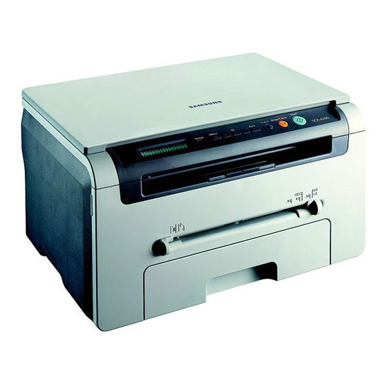
SCX-4200 Series
DIGITAL LASER MFP
SCX-4200 Series
SCX-4200/XAZ
Basic Model : SCX-4200
Manual
The keynote of Product
[ Key Features ]
- 18ppm Print/Copy Speed
- 600dpi Print/Copy Resolution
- 600 x 2400dpi Scan Resolution
- Samsung Print Language
- 8MB System Momory
- 250sh Paper Input/50sh Paper Output
- Under 42sec Warm-up Time
- 16 x 2 Line LCD Display
- USB 2.0
- 3K Toner Yield: initial(1K), sales(3K)
- Special Copy: ID Copy, Clone, 2-up, Poster,
Autofit
Advertisement
Table of Contents
Troubleshooting

Related Manuals for Samsung SCX-4200/XAZ


Summary of Contents for Samsung SCX-4200/XAZ
- Page 1 [ Key Features ] - 18ppm Print/Copy Speed - 600dpi Print/Copy Resolution - 600 x 2400dpi Scan Resolution - Samsung Print Language - 8MB System Momory - 250sh Paper Input/50sh Paper Output - Under 42sec Warm-up Time - 16 x 2 Line LCD Display - USB 2.0...
-
Page 2: Table Of Contents
Contents 1. Precautions 1.1 Safety Warning 1.2 Caution for safety 1.3 ESD Precautions 1.4 Super Capacitor or Lithium Battery Precautions 2. Product Specification 2.1 Product Overview 2.2 Specifications 3. System Overview 3.1 System Outline 3.2 H/W Structure abd Descriptions 3.3 S/W Structure and Descriptions 3-19 4. - Page 3 Continued 5. Disassembly and Reassembly 5.1 General Precautions on Disassembly 5.2 Front Cover 5.3 Rear Cover 5.4 DC Fan 5.5 Right Side Cover 5.6 Left Side Cover 5.7 Scanner Unit 5.8 OPE Unit 5-10 5.9 Middle Cover Unit 5-11 5.10 Fuser 5-12 5.11 Exit Roller 5-14...
- Page 4 Continued 7. Block diagram 7.1 System Block Diagram 8. Exploded Views & Parts List 8.1 Exploded Views and Parts List 9. Connection Diagram 9.1 SCX-4200 Connection Diagram 10. Schematic Diagram 10.1 Main Board 10-1 10.2 OPE Circuit Diagram 10-8 10.3 SMPS-110V 10-9 10.3 SMPS-220V 10-13...
-
Page 5: Precautions
High voltages and lasers inside this product are dangerous. This printer should only be serviced by a suitably trained and qualified service engineer. (2) Use only Samsung replacement parts There are no user serviceable parts inside the printer. Do not make any unauthorized changes or additions to the printer, these could cause the printer to malfunction and create electric shock or fire hazards. -
Page 6: Caution For Safety
Take care not to cut or damage the power cable or plugs when moving the machine. (9) Use caution during thunder or lightening storms. Samsung recommend that this machine be disconnected from the power source when such weather conditions are expected. Do not touch the machine or the power cord if it is still connected to the wall socket in these weather conditions. - Page 7 1.2.4 Assembly / Disassembly Precautions Replace parts carefully, always use Samsung parts. Take care to note the exact location of parts and also cable routing before dismantling any part of the machine. Ensure all parts and cables are replaced correctly.
- Page 8 Failure to do so could cause the printer to tip or fall possibly causing personal injury or damaging the printer. (5) Do not install the printer on a sloping or unstable surface. After installation, double check that the printer is stable. Service Manual Samsung Electronics...
-
Page 9: Esd Precautions
2. Be sure to replace the battery with the same or equivalent type recommended by the manufacturer. 3. Super capacitor or Lithium batteries contain toxic substances and should not be opened, crushed, or burned for disposal. 4. Dispose of used batteries according to the manufacture’s instructions. Service Manual Samsung Electronics... -
Page 10: Product Specification
Basic Model SCX-4200/SEE Series Model SCX-4200 Market of Sailes Persnal user MFP(Low Price for small work Group.) Specification 18ppm(Ltr. 19ppm), Chorus2(CPU : Use 16/32 Bit RISC Processor) 1K(initial), 3K(sailes) USB 2.0 250pages feeding, 50pages Face Down Service Manual Samsung Electronics... -
Page 11: Specifications
5 years, 50,000 Pages Whichever comes first. Approval Class B Device Memory Internal N/W Option Page Counter Print Configuration Sheet Maintenance Pickup Roller 50,000 Pages Separation Pad 50,000 Pages Transfer Roller 50,000 Pages Fuser Unit 50,000 Pages Service Manual Samsung Electronics... - Page 12 Max.216mm(8.5") Width Effiective Scan Max 208mm(8.2inch) Width Scan-to E-mail, Image, OCR, WEB "through PC --> Through PC means "from SmarThru4 application". Scan Depth Color 24 bit Mono 1bit for Lineart, Halftone, 8 Bit for Gray scale Service Manual Samsung Electronics...
- Page 13 Special Copy 2-up copy Yes(Platen only) Collation Copy AutoFit Copy Yes(Platen only) 2 Sides in 1 pg Yes(Platen only) * Copy 2-side printed original document into one page(ex. ID Card Copy) Clone Yes(Platen only) Poster Yes(Platen only) Service Manual Samsung Electronics...
- Page 14 With main tray paper 3/4,#9, #10,DL,C5,B5 Paper Weight Main Tray 16~24 lb. Bypass 16~43 lb. Paper Path Standard output Bottom to Top Front (FIFO) Straight Through Face up, Single Sheet Paper Size 216 x 356mm(8.5"x14") 76 x 127mm(3"x5") Compatibility Service Manual Samsung Electronics...
- Page 15 L-shape power cable Telephone Jack Printer Cable China,Korea : USB Type One Piece Consumables How to install Front door open and front loading Toner Life Initial 1Kpages running 3Kpages Toner Count Level Sensor Software Count Accessory Items Service Manual Samsung Electronics...
-
Page 16: System Overview
System Overview 3. System Overview This chapter describes the functions and operating principles of the main components. 3.1 System Outline 3.1.1 Front View Service Manual Samsung Electronics... - Page 17 System Overview 3.1.2 Sensor Service Manual Samsung Electronics...
- Page 18 System Overview 3.1.3 Control Panel Service Manual Samsung Electronics...
- Page 19 System Overview 3.1.4 System Layout SCAN PART Paper Input (Cassette) Paper Empty Sensor (Manual) Paper Empty Sensor (Cassette) Paper Input (Manual Feeder) Paper Out (Face Down) Paper Feeding Sensor Paper Out (Face Up) Paper Exit Sensor Service Manual Samsung Electronics...
- Page 20 The surface of the Heat Roller is heated by the Heat Lamp. As the paper passes between the Heat and Pressure rollers the toner is melted and fixed permanently to the paper. The surface of the roller is coated with Teflon. This ensures that toner does not adhere to the roller surface. Service Manual Samsung Electronics...
- Page 21 2.Scan Resolution : Color : Max 600DPI 3.Scan Width : 216mm 4.Function - White Shading Correction - Gamma Correction - CIS Interface - 256 Gray Scale • CIS Operating Part: CIS use +3.3V - CIS Max Operating Freguency: 5MHz Service Manual Samsung Electronics...
- Page 22 The controller detects the /HSYNC signal to adjust the vertical line of the image on paper. In other words after the /HSYNC signal is detected the image data is sent to the LSU to adjust the left margin on the paper. Service Manual Samsung Electronics...
- Page 23 - OPC Cleaning: Electrostatic process - Management of waste toner: Electro static process(Cleanerless Type) - OPC Drum protecting Shutter: No - Classifying device for toner cartridge: ID is classified by interruption of the frame channel 0.22mW -430V -970V -580V Service Manual Samsung Electronics...
-
Page 24: H/W Structure Abd Descriptions
- 5 Channel General Purpose DMA Controllers for High Speed I/O - Operation Frequency: System: 66MHz, Bus: 66MHz - Operation Voltage : 3.3V 2) Flash Memory : Record System Program, and download System Program by PC INTERFACE.. - Size: 1M Byte - Access time: 70 nsec Service Manual Samsung Electronics... - Page 25 - 4.5 MB: Printing System Working Memory Area - Max Frequency: 133MHz MEMORY DMA Controller CONTROLLER (IP_DMAC) IP_SFR ADDR-BUS ADDR-BUS ( ARM7TDMI) DATA-BUS DATA-BUS IP_MAIN Analog Signal Sensor Control Signal Scanner Motro Control Signal Motor IP_TOP IP_TOP interface Service Manual 3-10 Samsung Electronics...
- Page 26 Micom part, Matrix part and LCD. 2) Micom controller Micom has ROM, RAM, I/O Port built-in and displays and lights LCD by CPU command of Main Control Part and report Key recognition Data to Main Control Board. Service Manual 3-11 Samsung Electronics...
- Page 27 - ADC Interface Unit - 2 ADC Channels are available - ADC Core maximum clock frequency: 2.5 MHz USB 2.0 Interface Package : 208-LQFP-2828 Power : 1.8V(Core), 3.3V(IO) power operation Speed : 66MHz core(ARM7TDMI) operation, 60MHz bus operation Service Manual 3-12 Samsung Electronics...
- Page 28 BDMA (2-Ch.) Clock Generator (PPLL) USB v1.1 AIN[3:0] 10bit ADC GPIO Controller Watchdog Timer System Timer (4-ch) UART (2-ch) Rotator HP SIO (Real Time Clock) Tone Generator CRCON LFCON CRFIRE LSU I/F Parallel Port (P1284) Service Manual 3-13 Samsung Electronics...
- Page 29 THV/MHV/Supply/Dev and supplies it to the developer part for making best condition to display the image. The HVPS part takes the 24V and outputs the high voltage for THV/MHV/BIAS, and the outputted high voltage is supplied to the toner, OPC cartridge, and transfer roller. Service Manual 3-14 Samsung Electronics...
- Page 30 - Output Voltage Rising Time : 50 ms Max - Output Voltage Falling Time : 50 ms Max - Output Loading range : 10M ~ 1000 M - Output Control Signal (BIAS-PWM) : the CPU output is HV output when PWM is low. Service Manual 3-15 Samsung Electronics...
- Page 31 +5V 5% +24V-10/15% +24VS-10/15% (4.75~5.25V) (21.6~27.6V) (21.6~27.46V) Max. Output current 1.0A 0.5 A 1.0 A Peak Loading voltage 1.5A 1.0 A 1.5 A RIPPLE NOISE Under 150m Vp-p Under500mVp-p Under 500mVp-p Voltage Maximum output 5.0W Service Manual 3-16 Samsung Electronics...
- Page 32 - Maintaining Temperature Range: -25 ~ 85 - Preserving Humidity Condition: 30% ~ 90% RH - Operating Atmospheric Pressure Range: 1atm EMI Requirement: CISPR, FCC, CE, MIC Safety Requirement: IEC950 UL1950, CSA950, C-UL, Semko, CB, CCC(CCIB),GOST, EPA, Power Save Service Manual 3-17 Samsung Electronics...
- Page 33 Triac (THY1) feature :12A, 600V SWITCHING Phototriac Coupler (PC102) - Turn On If Current : 15mA ~ 50mA(Design: 16mA) - High Repetive Peak Off State Voltage : Min 600V Service Manual 3-18 Samsung Electronics...
-
Page 34: S/W Structure And Descriptions
Fuser Unit Power On Initial Engine Print Processing HVPS Control Module Fan Unit Motors Engine Unit Control Module Solenoid & Clutch Hardware Devices & Mechanical Device Sensors signals Fig 1. The architecture of the engine firmware Service Manual 3-19 Samsung Electronics... - Page 35 Second is a function that informs the main system of the current engine status for requested item. And there is function that calls sub-functions for specific operations that is request- ed by printer controller or printer engine firmware. Service Manual 3-20 Samsung Electronics...
- Page 36 It controls a fuser temperature and a pick-up time according to above paper type. Each control depends on its mechanism. Normally, papers with hard thickness are controlled by maintained a high temperature. But a paper like OHP is con- trolled at the lower temperature. Service Manual 3-21 Samsung Electronics...
- Page 37 If the printing job is done over the fixed time, the inner temperature of machine may be saturated. In this case, the engine keeps the temperature of the fixing unit with the specified temperature. The elapsed printing time is cleared at the sleep mode. Service Manual 3-22 Samsung Electronics...
- Page 38 It is very important to control the temperature of the fixing unit in the printing process and there are many require- ments for it. Therefore, a Temperature Table is defined and given by the fixing unit team. See the attachment. Service Manual 3-23 Samsung Electronics...
- Page 39 - If no error happens with above results, set up the values to mask the video data for horizontal and vertical region but if happens, it will be recovered according to the recovery sequence. Service Manual 3-24 Samsung Electronics...
- Page 40 ADC unit. It operates until the value is lower than a specified value. If the value is lower than a specified value, it decides an array index for the voltage and then searches an appropriate index in the table presented by the developer team Service Manual 3-25 Samsung Electronics...
- Page 41 A user can select one of pre-defined times as power save time from Driver UI. The setting value for power save time is OFF, 5min, 10min, 15min, 30min, 45min, and 60min. The default time is 5min. Although OFF is selected, power save time is operated 2 hours to protect fuser. Service Manual 3-26 Samsung Electronics...
- Page 42 LCD window. To remove the error: When the error is happened, if the user loads the paper in the paper feeder, then the error is removed. The developer team presents the cleaning process. Service Manual 3-27 Samsung Electronics...
- Page 43 LCD window informing the error status of the user. The specified time or steps will be decided based on the mechanical design length and the paper size. . When Paper Jam2 happens, fuser and fan is off. 3.3.14 Out Bin Tray Full Service Manual 3-28 Samsung Electronics...
- Page 44 In case of Over Heat Error, no heat is supplied to the fixing unit. When a specified time is elapsed, the engine detects a present temperature again. If the present temperature is a specified degree lower than the memorized temperature, the error is recovered. Service Manual 3-29 Samsung Electronics...
- Page 45 Hsync Error. If this error happens, the engine stops all functions and keeps it at the error state. Also, the engine informs the error status of the main system and then the error message is displayed at LCD window to inform the error status of the user. Service Manual 3-30 Samsung Electronics...
-
Page 46: Alignment And Adjustments
1 : On, 2 : Off (-1000V +300V/-150V) THV ON (1300V) 1 : On, 2 : Off (+1300V ± 20V) THV ADC 1300V 1 : On, 2 : Off THV ADC 600V~3550V 1 : On, 2 : Off (Compare each ADC Value) Service Manual Samsung Electronics... -
Page 47: Paper Path
4) The paper then passes through the paper exit sensor and out of the set. (Jam 2 occurs if the trailing edge of the paper does not pass the exit sensor within a certain time of the paper leading edge activating the exit sensor) Service Manual Samsung Electronics... -
Page 48: Clearing Paper Jams
See page 6-5 4 Insert the paper tray into the machine until it snaps into place. 5 Open and close the front cover to resume printing. Service Manual Samsung Electronics... - Page 49 If there is any resistance and the paper does not move when you pull or if you cannot see the paper in the jam cover, continue to step 6. Service Manual Samsung Electronics...
- Page 50 The error message may also occur when the paper is not properly fed into the machine through the manual feeder. In that case, pull the paper out of the machine. Service Manual Samsung Electronics...
-
Page 51: Printing The System Data List
To print the system data list: 1 Press Menu until "Report" appears on the top line of the display. "System Data" appears on the bottom line. 2 Press Start The system data list prints out. Service Manual Samsung Electronics... -
Page 52: Clearing The Memory
4 When the display asks you to confirm your selection, press Start The machine prints a cleaning page. Toner particles on the drum surface are affixed to the paper. 5 If the problem remains, repeat steps 1 through 4. Service Manual Samsung Electronics... -
Page 53: Consumables And Replacement Parts
• A paper jam has occurred in the manual • Clear the jam. feeder or the machine detects non- feeding from the manual feeder. Paper has jammed in the paper exit area. Paper Jam 2 Clear the jam. Check Inside Service Manual Samsung Electronics... -
Page 54: Periodic Defective Image
Heat Roller 64.0mm Black spot and image ghost Pressure Roller 75.3mm black spot on the backside MP Sensor Tramsfer Roller OPC Drum SCAN PART Heat Roller Charge Roller Pressure Roller Supply Roller Developing Roller <Rollers Layout> Service Manual Samsung Electronics... -
Page 55: Error Message
Scanner Error There is a problem in the scanner unit. Unplug the power cord and plug it back in. If the problem persists, please call for service. Service Manual 4-10 Samsung Electronics... - Page 56 This key is used to stop the job being done or to exit from the Menu. And clear value of 5 copy keys.. This key is used to select the right item what customer wants from several items. Left/Right Arrow Key Service Manual 4-11 Samsung Electronics...
- Page 57 This key is used to stop the job being done or to exit from the Menu. And clear value of 5 copy keys.. Stop This key is used to select the right item what customer wants from several items. Left/Right Arrow Key LED Color LED Status Discription Green Service Manual 4-12 Samsung Electronics...
-
Page 58: Disassembly And Reassembly
3. Unplug the power cord. 4. Use a flat and clean surface. 5. Replace only with authorized components. 6. Do not force plastic-material components. 7. Make sure all components are in their proper position. Service Manual Samsung Electronics... -
Page 59: Front Cover
3. To remove the Front Cover, first pull the part below the right side of the Front Cover with a light pressure to the direction of arrow and then remove the Front Cover, as shown below. Cassette 2. Open the Front Cover. Front Cover Service Manual Samsung Electronics... -
Page 60: Rear Cover
Rear Door 2. To remove the Rear Cover make sure the Power Switch doesn't get jammed to Rear Cover and then Unplug the one connector(DC Fan) from the Main PBA, as shown below. Rear Cover Service Manual Samsung Electronics... -
Page 61: Dc Fan
- Rear Cover (Refer to 5.3) 2. First release the harness from the Harness Holder and then remove the one screw securing the Harness Holder and remove it, as shown below. DC Fan Harness Holder (24V, 80mA) Service Manual Samsung Electronics... -
Page 62: Right Side Cover
3. Apply light pressure to the back of the Right Side Micro Switch and remove it. Cover and pull it to the right side in the direction of arrow, as shown below. Right Side Cover Micro Switch Right Side Cover Service Manual Samsung Electronics... -
Page 63: Left Side Cover
- Front Cover (Refer to 5.2) shown below. - Rear Cover (Refer to 5.3) 2. Remove the one screw at the front of the unit. Left Side Cover Service Manual Samsung Electronics... -
Page 64: Scanner Unit
OPE Unit with a light pressure to the direction of arrow. 3. Carefully lift the Scanner Unit from the base taking care to thread the cables through the frame. Scanner Unit CIS FFC OPE Unit Scan Motor Service Manual Samsung Electronics... - Page 65 CIS FFC from the CIS and remove two CIS Slider from each end of the CIS. Then Release the CIS in the direction of arrow, as shown below. CIS Slider CIS Slider CIS FFC Carriage Service Manual Samsung Electronics...
- Page 66 Pulley Idle Pulley Bracket Carriage Belt Belt Clip 12. Take the CIS Shaft out of OPE Lower Unit and then remove the three screws securing the Scan Motor Ass'y and remove it. CIS Shaft Scan Motor Ass'y Service Manual Samsung Electronics...
-
Page 67: Ope Unit
1. Lift the Platen Cover upward and remove it. 2. To remove OPE Unit, first pull the part below the front of the OPE Unit with a light pressure to the direction 4. Release the Keys. of arrow. OPE Unit LED Cap Service Manual 5-10 Samsung Electronics... -
Page 68: Middle Cover Unit
1. Before you remove the Middle Cover Unit, you should remove: - Scanner Unit (Refer to 5.7) 2. Remove the four screws securing the Middle Cover Unit and remove it, as shown below. Middle Cover Unit Service Manual 5-11 Samsung Electronics... -
Page 69: Fuser
Harness from both side of the Halogen Lamp, as shown below. Then take the Halogen Lamp out of the Heat Roller. Fuser Heat Roller Halogen Lamp Notice: Remove the Fuser taking care not to damage the Exit Sensor. Service Manual 5-12 Samsung Electronics... - Page 70 8. Unwrap the Thermistor Harness, as shown below. RDCN(25/15) and remove it. Thermister Harness Gear RDCN(25/15) 9. Remove the Thermistor from the Fuser Cover. 7. Remove the four screws and divide the Fuser into two parts. Thermister Service Manual 5-13 Samsung Electronics...
-
Page 71: Exit Roller
2. Remove the Exit Gear and Bearing using a screw dri- ver at one end then remove the shaft and rollers, as shown below. Exit Gear Bearing Roller Exit F/Down Roller Exit Main Roller Exit FR Holder Service Manual 5-14 Samsung Electronics... -
Page 72: Lsu
- Scanner Unit (Refer to 5.7) - Middle Cover Unit (Refer to 5.9) 2. Remove the one screw securing the CAP LSU and remove it. CAP LSU 3. Unplug the two connectors from the LSU. Service Manual 5-15 Samsung Electronics... -
Page 73: Fan
. Left Side Cover (Refer to 5.6) Drive Ass'y 2. Remove the six screws securing the Drive Ass'y. Notice: When refitting the Drive Ass'y tighten the screws in the order that they are numbered on the Drive Ass'y base plate. Service Manual 5-16 Samsung Electronics... -
Page 74: Engine Shield Ass'y
2. Unplug the Engine Harness and remove the two remove: screws from the Main PBA. Then lift the Main PBA - Engine Shield Ass'y (Refer to 5.15) out, as shown below. Main PBA Engin Harness Service Manual 5-17 Samsung Electronics... -
Page 75: Smps
2. Remove the two screws then take the Inlet Bracket out, as shown below. Inlet Bracket 3. Unplug the Engine Harness from the SMPS and then remove the one screw securing the ground cable, as shown below. Engine Harness Service Manual 5-18 Samsung Electronics... -
Page 76: Crum Pcb
1. Before you remove the CRUM PCB, you should remove: - LSU (Refer to 5.12) - Engine Shield Ass'y (Refer to 5.15) 2. Remove the four screws securing the CRUM PCB and remove it, as shown below. CRUM PCB Service Manual 5-19 Samsung Electronics... -
Page 77: Transfer Roller
3. Unplug the PTL PBA Harness then remove the PTL Holder and PTL Lens, as shown below. Take care to note the orientation of the PTL Lens and ensure it is refitted correctly. Lens Holder PTL PBA Harness Service Manual 5-20 Samsung Electronics... -
Page 78: Feed Roller
Guide Paper 5. Remove the Idle Gear and Feed Gear2. Feed Gear2 3. Pull up the Feed Idle Bush and Feed Idle Shaft, as shown below. Feed Idle Shaft Spring Idle Gear Bush Service Manual 5-21 Samsung Electronics... - Page 79 Disassembly and Reassembly 6. Remove the Feed Gear1 Ass'y, as shown below. 7. Pull the Feed Roller and Feed Roller1, as shown below. Feed Gear1 Feed Roller Ass'y Feed Roller1 Service Manual 5-22 Samsung Electronics...
-
Page 80: Pick Up Roller & Solenoid
3. To remove the Pick Up Ass'y, first lift the notch attached to the Bush so that it's released from the shaft, then slide the Pick Up Ass'y from right to left and it will be released completely, as shown below. Bush Pick Up Ass'y Service Manual 5-23 Samsung Electronics... - Page 81 Disassembly and Reassembly Service Manual 5-24 Samsung Electronics...
-
Page 82: Troubleshooting
- Power Module error OP Panel - Main PBA error - LCD Panel error Refer to Indicate Ready or Error Massage Error Massage Power save <Chapter 4.10> Test Print printing Refer to "Solution Quality is of Image Problem" Nomal? Service Manual Samsung Electronics... - Page 83 1. Replace the toner cartridge and test Digital Printer Doctor-blade in the Toner cartridge. again. Digital Printer 2. Scratched surface of the charge roller in 2. Replace the toner cartridge and test Digital Printer the toner cartridge. again. Digital Printer Service Manual Samsung Electronics...
- Page 84 Remove if found. 5. Contamination of the OPC drum. 5. If the problems are not solved, replace the toner cartridge. Service Manual Samsung Electronics...
- Page 85 If the roller's life is expired, transfer roller's life has expired. replace it. Note. Cleaning the inside of the set to remove excess toner particles or paper dust will reduce the occurrence of this problem.. Service Manual Samsung Electronics...
- Page 86 Note if 1 and 2 do not resolve the problem Digital Printer and the problem persists replace the HVPS. 3. VD0 signal of the Main PBA is Low state. 3. Replace the LSU Unit or Main PBA. Service Manual Samsung Electronics...
- Page 87 4. Is the movement(Up and Down) of 4. Clean the transfer roller bushes. the transfer roller smooth? 5. Is the HVPS normal? 5. Clean the high voltage charge terminals. If this does not resolve the problem replace the HVPS. Service Manual Samsung Electronics...
- Page 88 Digital Printer OHP, a higher transfer voltage is required. Remember to set back to normal paper after Digital Printer use. Digital Printer Digital Printer Service Manual Samsung Electronics...
- Page 89 Digital Printer toner cartridge. Digital Printer 2. If the transfer roller is contaminated, run Digital Printer PC Cleaning Mode Print 2 or 3 times and Digital Printer then perform Self-Test 2 or 3 times to remove contamination. Service Manual Samsung Electronics...
- Page 90 3. When the printer turns on, several blank pages print. Check and Cause Solution 1. Abnormal solenoid. 1. Perform the engine self test using TECH Mode to check if the Solenoid is normal. If the problem persists replace the main Service Manual Samsung Electronics...
- Page 91 Black page is printed out when Copying. Check and Cause Solution 1. Check for CIS problem on the Main PBA. 1. Check the CIS harness is properly connected. 2. Check shading profile. 2. Redo shading profile in the tech mode. Service Manual 6-10 Samsung Electronics...
- Page 92 2. Check the gap between original and scanner 2. A gap of more than 0.5 mm can cause a blurred glass. image. Ensure cover close correctly. Replace as necessary. 3. Check printing quality. 3. See "Print" troubleshooting. Service Manual 6-11 Samsung Electronics...
- Page 93 6 If the paper feeds into the printer and 6. Check the SMPS PBA, Main PBA and Jam 0 occurs, perform Tech Mode to all connections. Replace any faulty check feed sensor. parts or the Service Manual 6-12 Samsung Electronics...
- Page 94 Check all ribs, claws and springs. • It occurs when the Spring of a Guide claw is broken or damaged. • It occurs when the Heat-Roller or Pressure-Roller is seriously contaminated with toner. Service Manual 6-13 Samsung Electronics...
- Page 95 Clean the surface of the rollers with IPA or water 2. Damaged or deformed ribs, claws or springs. 2. Check for damage or deformation of the print claws and the holder plate claws, and repair or replace as appropriate. Service Manual 6-14 Samsung Electronics...
- Page 96 Use the gearwheel at the side to rotate the OPC drum and pull the paper from the cassette. • Clean fingerprints on the OPC gently with soft tissue, taking care not to scratch the surface. Service Manual 6-15 Samsung Electronics...
- Page 97 Use TECH mode to test the LSU - Replace the LSU 2. LSU motor is faulty. - Replace a main board if the same error persists after replacing a LSU. 3. Check the HSYNC signal. Service Manual 6-16 Samsung Electronics...
- Page 98 1. Deformed paper sensor actuator or faulty sensor. 1. Replace the defective actuator or sensor. 2. SMPS PBA or Main PBA is defective 2. Replace the SMPS PBA or MAIN PBA as appropriate. 3. Faulty cables or connectors. Service Manual 6-17 Samsung Electronics...
- Page 99 2. The tab on the front cover may be damaged or broken 2. Replace the front cover. 3. Check the connector and cables between Switch and 3. Replace the Main Control board or Cover Open main PBA. S/W as necessary. Service Manual 6-18 Samsung Electronics...
- Page 100 1. Use TECH mode(“cover sensor test”) to check cover switch operation. Check and replace switch if necessary. 2. Check the connector and cables between Switch and main PBA. 2. Replace the Main Control board or Cover Open S/W as necessary. Service Manual 6-19 Samsung Electronics...
- Page 101 2. LCD panel does not come on but normal start up 2. Replace the OP panel. sounds are heard. 3. After replacing SMPS display does not come on and no 3. Replace the main PBA panel. start up sounds are heard. Service Manual 6-20 Samsung Electronics...
- Page 102 When printing, vertical lines are not straight. Check and Cause Solution 1. Check stability of 24V supply to LSU. 1. 24V stable - Replace LSU. 24V unstable replace SMPS, if the problem persists replace the main PBA. Service Manual Samsung Electronics...
- Page 103 Troubleshooting 6.6 Toner Cartridge Service Only toner cartridges supplied by Samsung should be used. Printing defects or set damage caused by the use of non-approved toner cartridges or un-licensed toner refills are not covered by the guarantee. 6.6.1 Precautions on Safe-keeping of Toner Cartridge Excessive exposure to direct light for more than a few minutes may cause damage to the cartridge.
- Page 104 (a) Check that the terminals problem persists replace the (contact points) of the toner cartridge. cartridge and the set are clean. (b) Check that the terminals (contact points) of the toner cartridge and the set are not damaged. Service Manual 6-23 Samsung Electronics...
- Page 105 (contact point) of the toner toner cartridge is recycled over cartridge and the set are not 2 times. damaged. If ‘nearly empty’ cartridges are collected for re-use this is judged as recycling the toner cartridge. Service Manual 6-24 Samsung Electronics...
- Page 106 (a) Check if foreign substances are stuck to the terminal (point of contact) of the toner cartridge or set. (b) Check if the terminal assembly is normal. (Especially check the developer roller terminal.) Service Manual 6-25 Samsung Electronics...
- Page 107 2. Ensure that the correct driver is loaded. Use the driver supplied on the CD or downloaded from the Samsung web site. DO NOT use the Microsoft driver supplied with the Windows operating system. If the printer is a GDI or SPL type printer ensure that...
- Page 108 If there is a problem with the printer (out of toner, offline, out of paper etc.) the job may take a long time to delete as it must wait for a time out. Service Manual 6-27 Samsung Electronics...
-
Page 109: Block Diagram
Block Diagram 7. Block Diagram 7.1 System Block Diagram Service Manual Samsung Electronics... - Page 110 This format is used throughout Samsung on all product ranges. Typically it is used for small components and electronic parts. This format is controlled by individual Samsung Divisions and is used on specific products, typically for mechanical parts. Type 2 format part numbers fall into 2 categories: Assemblies consisting of 2 or more parts.
- Page 111 Exploded Views & Parts List 8.1 Main Exploded View Service Manual...
- Page 112 Exploded Views & Parts List 8.2. Housing Base Exploded View Service Manual...
- Page 113 Exploded Views & Parts List 8.3. Frame Assembly Exploded View Service Manual...
- Page 114 Exploded Views & Parts List 8.4. Fuser Unit Exploded View Service Manual...
- Page 115 Exploded Views & Parts List 8.5. Drive Assembly Exploded View Service Manual...
- Page 116 Exploded Views & Parts List 8.6. Scan Assembly Exploded View Service Manual...
- Page 117 Exploded Views & Parts List 8.7. OPE Assembly Exploded View Service Manual...
- Page 118 Exploded Views & Parts List 8.8. Cassette Assembly Exploded View Service Manual...
- Page 119 Parts List Service Parts List (Model code : SCX-4200/XAZ) SA : SERVICE AVAILABLE SNA : SERVICE not AVAILABLE DNA : DELIVERY not AVAILABLE Drawer# SEC-Code Description & Specification Location Service 8.1-1 JC96-03807A ELA HOU BASE-HOUSING;SCX-4200,SEC,-,-,-, 8.1-2 3103-001085 FAN-DC;24V,80mA,4800rpm,-,0.131mmH20 8.1-3 JC61-01643A HOLDER-M_HARNESS;SCX-4200,ABS, HB,2.0,15...
- Page 120 GEAR-FEED 2;ML-1710,POM(M90-44),-,-,-,NT F6072 8.3-45-1 JC72-00980A PMO-GEAR PICK_UP B;ML-1710,POM(M90-44),N P2126 8.3-45-2 JC72-00979A PMO-GEAR PICK_UP A;ML-1710,POM(M90-44),N P6221 8.3-45-3 6107-001167 SPRING-CS;SUS304-WPB,-,PI0.25,D3.25,L9.6 Z4318 8.3-B JC97-01788A MEA UNIT-CLUTCH;ML-1710,SAMSUNG,-,-,-,-, C9040 8.3-46-1 JC66-00393A GEAR-FEED 1;ML-1710,POM(DELIN 8903),-,-, F6071 8.3-46-2 JC72-00978A PMO-COLLAR_SPRING;ML-1710,POM(M90-44),NT Z4125 8.3-46-3 6107-001171 SPRING-TS;SWRS82A,-,0.75X0.5,D14.2,-,-,- Z4161 8.3-46-4 JC72-00981A PMO-HUB CLUTCH;ML-1710,POM(M90-44),NTR,-...
- Page 121 IPR-P-GROUND_GUIDE PAPER;ML-1710,C5210P, G2285 8.3-61 JC70-00307A IPR-P-EARTH TRANSFER;ML-1710,SECC,-,1.0T O1094 8.3-62 JC67-00027A LENS-PTL;ML-1710,PMMA,NTR,-,-,-,- K3433 8.3-63 JC61-00583A HOLDER-PTL;ML-1710,PC,-,-,-,BLK,V0 H4041 8.3-64 JC92-01841A PBA SUB-PTL;SF-560/EUE,SAMSUNG,-,-,-,-,- 8.3-65 JC61-00588A BUSH-M-TR L;ML-1710,POM(M90-44),-,-,-,BL K2886 8.3-66 JC61-00047A SPRING ETC-TR L HAWK;ML-6060A,SWP-B,-,-, O1030 8.3-67 JC72-00102A PMO-BUSHING_TR(L);SF-5100,POM (CH-15),BL O1101 8.3-69 JC96-03808A ELA HOU-FUSER;SCX-4200,SAMSUNG,-,110V,-, 8.3-70...
- Page 122 LABEL(P)-SHADING;COMMON,YOOPO PAPER ,T0. Z4177 8.6-6 JB01-00002A GLASS-PLATEN;247*356,2.85,CLEAR Z4178 8.6-7 JC63-01014A COVER-M-SCAN LOWER;SCX-4200,HIPS,T2.2,40 8.6-8 JC63-00459A SHEET-SCAN LOWER;SCX-4100,PET,T0.188,-,- 8.6-9 JC61-00931A BRACKET-P-PULLEY;SCX-4100,SECC,0.8,-,-,- 8.6-A JC96-03834A ELA UNIT-SCAN DRIVE;SCX-4200,SAMSUNG,-,1 8.6-10 JC66-00713A PULLEY-M_IDLE;SCX-4100,POM,-,WHT,-,-,-,- 8.6-11 6107-001194 SPRING-CS;SWP-B,BLK,PI0.9,D6.95,L20,-,-, S0032 8.6-12 JC31-00049A MOTOR STEP-SCAN;2T357278Q,SCX-4200,0.2A, 8.6-13 JC61-01640A BRACKET MOTOR-P-SCAN;SCX-4200,SECC,T1.0, 8.6-14 JC66-01201A GEAR-M_PULLEY;SCX-4200,POM,0.4,73,-,-,31 8.6-15...
- Page 123 8.8-19 JC66-00719A CAM-M-KNOCK UP;ML-1750,POM(KOLON K700),- 8.8-20 JC73-00141A RPR-PAD CASSETTE;ML-1510,URETHANE SPONGE R0020 Replacement JC69-00932A BOX(P)-MAIN;SCX-4200/XAA,DW,OFFSET4,321, #N/A JC68-01653B MANUAL-QIG2;SCX-4200,SAMSUNG,RU+SC+TC,RU #N/A JC96-02663C ELA ETC-SHIELD PCB;SCX-4200,SAMSUNG,-,-, #N/A JC96-03206A ELA UNIT-SMPS V1 #N/A JC96-03826A ELA HOU-ENGINE;SCX-4200,SEC,-,-,-,-,- #N/A JC99-01937A PAA-PACKING;SCX-4200/XAA,US,-,-,-,- #N/A JC99-01939N PAA WOOD-LABEL;SCX-4200/XAZ,BRAZIL,-,-,- #N/A JC99-01946T INA-ACCESSORY;SCX-4200,XAZ,SEC,-,-,-...
- Page 124 Parts List SA : SERVICE AVAILABLE SNA : SERVICE not AVAILABLE DNA : DELIVERY not AVAILABLE Drawer# SEC-Code Description & Specification Location Service #N/A JC69-00933B CUSHION-MAIN(L);SCX-4200/XAA,EPS,-,506,1 #N/A JC92-01840A PBA MAIN-DEV;SCX-4920N/DEL,DELL,-,-,-,-, #N/A JC94-01097A PHANTOM AU JC92-01762A #N/A JC96-03806A ELA UNIT-SCAN LOWER;SCX-4200,SEC,-,-,-,- #N/A JC97-02430A MEA-DEVE KIT;SCX-4200,SEC,-,-,-,-,-...
- Page 125 ROLLER-DEVELOPER;SCX-4200,CONDUCTIVE NBR #N/A JC67-00028A CAP-M-DEV L;ML-1710,ABS,2,-,-,-,19*24.7* #N/A JC67-00029A CAP-M-DEV R;ML-1710,ABS,2,-,-,-,19*24.7* #N/A JC68-00408A LABEL(R)-LV FUSER;COMMON,PVC,-,110V,-,,, #N/A JC68-01040A MANUAL-CARD PROTECTION;ML-1710,SEC,-,-,- #N/A JC68-01085K LABEL(P)-EXTRACT;SCX-4200/XAA,SAMSUNG,AR #N/A JC68-10914D LABEL(P)-SERIAL NO;ML-85,ART,70X15,G100, #N/A JC69-00078A BAG PE;CONDUTIVE T0.1,T=0.1,-,190*410,-, #N/A JC70-00050A IPR-TERMINAL;SF-5100,SWRCH1018,-,-,-,-,8 #N/A JC70-00153A IPR-ELECTRODE CHARGE;ML-4500,SUS301,-,8. #N/A JC70-00483A ELECTRODE-P_SR(M);SCX-4100,SUS301-CSP T0...
- Page 126 Parts List SA : SERVICE AVAILABLE SNA : SERVICE not AVAILABLE DNA : DELIVERY not AVAILABLE Drawer# SEC-Code Description & Specification Location Service #N/A JC72-00083A PMO-HOLDER CR;SF-5100,POM,BLK,-,-,-,-,-, #N/A JC72-00288A PPR-SPACER DR;SF-5100,PET FILM, T0.1,-,- #N/A JC72-00288B PPR-SPACER DR R;SF-5100,TEFRON,WHT,-,-,T #N/A JC72-00289B PPR-FILM REAR;ML-1210,PET FILM,-,0.08T,- #N/A JC72-01234A...
- Page 127 Parts List SA : SERVICE AVAILABLE SNA : SERVICE not AVAILABLE DNA : DELIVERY not AVAILABLE Drawer# SEC-Code Description & Specification Location Service #N/A 2203-000357 C-CER,CHIP;0.15nF,5%,50V,C0G,1608 #N/A 2203-000626 C-CER,CHIP;0.022nF,5%,50V,C0G,1608 #N/A 2203-000998 C-CER,CHIP;0.047nF,5%,50V,C0G,1608 #N/A 2203-005819 C-CER,CHIP;1000nF,+80-20%,16V,Y5V,-,1608 #N/A 2404-001102 C-TA,CHIP;33uF,20%,16V,GP,TP,6032,- #N/A 2802-001069 RESONATOR-CERAMIC;7.37MHz,0.5%,TP,4.7x4.
-
Page 128: Connection Diagram
Connection Diagram 9. Connection Diagram 9.1 SCX-4200 Connection Diagram Service Manual Samsung Electronics... -
Page 129: Schematic Diagram
REV 0.3 ASIC (CHORUS 2) SDRAM, FLASH ROM LSU, SMPS, PANEL, COVER OPEN == MEMO == CIS, SCAN MOTOR FUSER, MAIN MOTOR, CLUTCHES PTL, FAN2 USB2.0, CRUM Service Manual 10-1 Samsung Electronics This Document can not be used without Samsung’s authorization. -
Page 130: Main Board
Main Board(2/7) Schematic Diagram INSTPAR INSTPAR Service Manual 10-2 Samsung Electronics This Document can not be used without Samsung’s authorization. - Page 131 DQ15 DQ14 DQ13 DQ12 DQ11 DQ10 *RAS *CAS VDD1 VDD2 VDD3 VDDQ1 VDDQ2 VDDQ3 VDDQ4 *LDQM VSS1 *HDQM VSS2 VSS3 VSSQ1 VSSQ2 VSSQ3 CLKE VSSQ4 K4S641632H-TC75 Service Manual 10-3 Samsung Electronics This Document can not be used without Samsung’s authorization.
- Page 132 Main Board(4/7) Schematic Diagram Not used Service Manual 10-4 Samsung Electronics This Document can not be used without Samsung’s authorization.
- Page 133 Main Board(5/7) Schematic Diagram INSTPAR Not Used Not Used Not Used Service Manual 10-5 Samsung Electronics This Document can not be used without Samsung’s authorization.
- Page 134 Main Board(6/7) Schematic Diagram Service Manual 10-6 Samsung Electronics This Document can not be used without Samsung’s authorization.
- Page 135 Main Board(7/7) Schematic Diagram Service Manual 10-7 Samsung Electronics This Document can not be used without Samsung’s authorization.
-
Page 136: Ope Circuit Diagram
Schematic Diagram BASIC (LCD1) BASIC (LCD1) CHIN CHINA/KOREA (LCD2) A/KOREA (LCD2) MI MICO CO M M (U1) (U1) JB13-00004A JB13-00004A JB13-00035A JB13-00035A JB07-00004A JB07-00004A JC07-00008A JC07-00008A Service Manual 10-8 Samsung Electronics This Document can not be used without Samsung’s authorization. - Page 137 10.3 SMPS-110V(1/4) Schematic Diagram Service Manual 10-9 Samsung Electronics This Document can not be used without Samsung’s authorization.
-
Page 138: Smps-110V
SMPS-110V(2/4) Schematic Diagram Service Manual 10-10 Samsung Electronics This Document can not be used without Samsung’s authorization. - Page 139 SMPS-110V(3/4) Schematic Diagram Service Manual 10-11 Samsung Electronics This Document can not be used without Samsung’s authorization.
- Page 140 SMPS-110V(4/4) Schematic Diagram Service Manual 10-12 Samsung Electronics This Document can not be used without Samsung’s authorization.
-
Page 141: Smps-220V
10.3 SMPS-220V(1/4) Schematic Diagram Service Manual 10-13 Samsung Electronics This Document can not be used without Samsung’s authorization. - Page 142 SMPS-220V(2/4) Schematic Diagram Service Manual 10-14 Samsung Electronics This Document can not be used without Samsung’s authorization.
- Page 143 SMPS-220V(3/4) Schematic Diagram Service Manual 10-15 Samsung Electronics This Document can not be used without Samsung’s authorization.
- Page 144 SMPS-220V(4/4) Schematic Diagram Service Manual 10-16 Samsung Electronics This Document can not be used without Samsung’s authorization.
-
Page 145: Reference Information
M2 long, M2 short). Spring Hook Standard : For general use Tweezers Standard : For general home use, small type. Software(Driver) installation CD ROM Cotton Swab Standard : For general home use, for medical service. Service Manual 11-1 Samsung Electronics... -
Page 146: Acronyms And Abbreviations
Integrated Drive Electronics EEPROM Electronically Erasable Programmable Read Only Memory IEEE Institute of Electrical and Electronics Engineers. Inc Electro Magnetic Interference Image Output Terminal (Color print- Electro photographic er, Copier) Enhanced Parallel Port Isopropy Alcohol Service Manual 11-2 Samsung Electronics... - Page 147 Read Only Memory Liquid Crystal Display SCF/SCT Second Cassette Feeder/Second Cassette Tray Light Emitting Diode SMPS Switching Mode Power Supply Laser Scanning Unit SPGP Samsung Printer Graphic Megabyte Processor Multi-Functional Product Samsung Printer Language Megahertz Spool Simultaneous Peripheral Operation Online MPBF...
-
Page 148: Select A Location For The Printer
• Provide the proper environment : - A firm, level surface - Away from the direct airflow of air conditioners, heaters, or ventilators - Free of extreme fluctuations of temperature, sunlight, or humidity - Clean, dry, and free of dust Service Manual 11-4 Samsung Electronics... -
Page 149: A4 Iso 19752 Standard Pattern
Reference Information 11.4 A4 ISO 19752 Standard Pattern This test page is reproduced at 70% of the normal A4 size Service Manual 11-5 Samsung Electronics... - Page 150 ELECTRONICS * This service manual is a property of Samsung Electronics Co., Ltd. Any unauthorized use of Manual can be punished under applicable international and/or domestic law. Samsung Electronics Co.,Ltd. November. 2005 * This service manual is also provided on the web, the ITSELF Printed in Korea.