
Related Manuals for National Instruments BNC-2090A


Summary of Contents for National Instruments BNC-2090A
- Page 1 BNC-2090A User Manual Rack-Mount Connector Accessory for E/M Series DAQ Devices BNC-2090A User Manual January 2007 372101A-01...
- Page 2 Thailand 662 278 6777, Turkey 90 212 279 3031, United Kingdom 44 (0) 1635 523545 For further support information, refer to the Technical Support and Professional Services appendix. To comment on National Instruments documentation, refer to the National Instruments Web site at and enter ni.com/info the info code feedback ©...
- Page 3 Instruments Corporation. National Instruments respects the intellectual property of others, and we ask our users to do the same. NI software is protected by copyright and other intellectual property laws. Where NI software may be used to reproduce software or other materials belonging to others, you may use NI software only to reproduce materials that you may reproduce in accordance with the terms of any applicable license or other legal restriction.
- Page 4 These classes are known as Class A (for use in industrial-commercial locations only) or Class B (for use in residential or commercial locations). All National Instruments (NI) products are FCC Class A products. Depending on where it is operated, this Class A product could be subject to restrictions in the FCC rules. (In Canada, the Department of Communications (DOC), of Industry Canada, regulates wireless interference in much the same way.) Digital...
- Page 5 Conventions The following conventions are used in this manual: <> Angle brackets that contain numbers separated by an ellipsis represent a range of values associated with a bit or signal name—for example, AO <3..0>. » The » symbol leads you through nested menu items and dialog box options to a final action.
-
Page 6: Table Of Contents
Contents Chapter 1 BNC-2090A Overview What You Need to Get Started ..................1-2 Installing the BNC-2090A .....................1-3 Setting the BNC-2090A Shield Ground Jumper............1-7 Chapter 2 Connecting Signals Connecting Analog Input Signals ..................2-1 Connecting Differential Analog Input Signals ..........2-2 Measuring Floating Signals in Differential Input Mode ....2-2 Measuring Ground-Referenced Signals in Differential Input Mode ..................2-3... - Page 7 Contents Appendix A Specifications Appendix B Frequently Asked Questions Appendix C Technical Support and Professional Services Index BNC-2090A User Manual viii ni.com...
-
Page 8: Bnc-2090A Overview
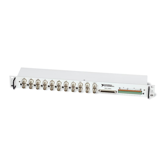
Refer to the BNC-2090A Quick Start Guide for basic installation and signal connection instructions. Figure 1-1 shows the front panel and enclosure back of the BNC-2090A. You can also use the BNC-2090A with PCI-6013 and PCI-6014 B Series devices. © National Instruments Corporation BNC-2090A User Manual... -
Page 9: What You Need To Get Started
The E Series User Manual or the M Series User Manual ❑ BNC cables ❑ 20 AWG wire or smaller ❑ Wire strippers Two-connector M Series devices can be cabled to two BNC-2090A accessories with two cables. BNC-2090A User Manual ni.com... -
Page 10: Installing The Bnc-2090A
❑ Small flathead screwdriver ❑ Four adhesive rubber feet (supplied) You can find detailed specifications for the BNC-2090A in Appendix A, Specifications. Installing the BNC-2090A The BNC-2090A Quick Start Guide contains general installation information for the BNC-2090A. To connect the BNC-2090A to your DAQ device, refer to Figure 1-2 as you complete the following steps. - Page 11 Do not connect the BNC-2090A to any device other than a National Instruments Caution E Series or M Series DAQ device. Doing so can damage the BNC-2090A, the DAQ device, or host computer. National Instruments is not liable for damages resulting from these connections.
- Page 12 Connector SH68-68-EP or R6868 Cable M Series USB SH68-68-EP or R6868 Cable Mass Termination DAQ Device 68-Position BNC-2090A Connector 68-Position Connector Figure 1-3. Direct Connection of M Series DAQ Devices to the BNC-2090A © National Instruments Corporation BNC-2090A User Manual...
- Page 13 Do not connect input voltages greater than 42.4 V /60 VDC to the BNC-2090A. Caution The BNC-2090A is not designed for any input voltages greater than 42.4 V /60 VDC, even if a user-installed voltage divider reduces the voltage to within the input range of the DAQ device.
-
Page 14: Setting The Bnc-2090A Shield Ground Jumper
BNC-2090A Overview all devices connected to it, and the host computer. Overvoltage can also cause an electric shock hazard for the operator. National Instruments is not liable for damage or injury resulting from such misuse. Setting the BNC-2090A Shield Ground Jumper... - Page 15 Remove the top and bottom screws and two front panel screws. Hold the front panel and slide the unit out of the metal case. Set the shield ground jumper, labeled W1 on the PCB, as needed. Reassemble the BNC-2090A in reverse order. BNC-2090A User Manual ni.com...
-
Page 16: Connecting Signals
Connecting Signals The BNC-2090A features 22 BNC connectors and a spring terminal block for analog and digital signal connection. Refer to the E Series User Manual or the M Series User Manual for information about the use of these signals. -
Page 17: Connecting Differential Analog Input Signals
AI <0..7> BNC connector you use. Move the corresponding SE/DIFF switch to the DIFF position. On the BNC-2090A front panel, a line indicates which SE/DIFF switch corresponds to each AI <0..7> BNC connector. Configure your software to measure this channel differentially. -
Page 18: Measuring Ground-Referenced Signals In Differential Input Mode
If the DAQ device is configured for differential inputs, ground-referenced signal sources connected to the BNC-2090A need no special components added to the BNC-2090A. You can leave the inputs of the BNC-2090A in the factory-default configuration, with the 0 Ω jumpers in the two series... -
Page 19: Measuring Floating Signals In Single-Ended Input Mode
When measuring floating signal sources, configure the DAQ device to supply a ground reference by placing the device in referenced single-ended (RSE) mode. This mode ties the negative input of the DAQ device instrumentation amplifier and the BNC shield to the analog ground. BNC-2090A User Manual ni.com... -
Page 20: Measuring Ground-Referenced Signals In Single-Ended Input Mode
Connecting AO, APFI 0, and PFI 0 Signals Use the BNC-2090A BNC connectors on the front panel to connect AO <0..1>, APFI 0, and PFI 0 signals to your DAQ device. Refer to the E Series User Manual or the M Series User Manual for information about the use of these signals. -
Page 21: Connecting Digital Signals
Connecting Digital Signals Use the BNC-2090A spring terminal block on the front panel to connect digital signals to your DAQ device. Refer to the E Series User Manual or the M Series User Manual for information about the use of these signals. -
Page 22: Using The User 1 And User 2 Bnc Connectors
The USER 1 and USER 2 BNC connectors allow you to use a BNC connector for a digital or timing I/O signal of your choice. The USER 1 and USER 2 BNC connectors are routed (internal to the BNC-2090A) to the USER1 and USER2 spring terminals, as shown in Figure 2-5. -
Page 23: Signal Conditioning
Signal Conditioning This chapter contains information about adding signal conditioning components to the BNC-2090A and signal conditioning examples for using the BNC-2090A with your DAQ device. Analog Input Signal Conditioning Each analog input signal has several open positions for passive signal conditioning components. - Page 24 Figure 3-1 shows the onboard components for differential mode. COMMON DIFF AI 8 AI 0 Do Not Connect AI GND Factory-Installed 0 Ω Jumpers AI GND AI 8 AI 0 To Input Multiplexer of DAQ Device Figure 3-1. Channel 0 Differential Mode Onboard Components BNC-2090A User Manual ni.com...
- Page 25 AI 8 AI 0 AI GND Factory-Installed 0 Ω Jumpers AI GND AI 8 AI 0 To Input Multiplexer of DAQ Device Figure 3-2. Channel 0 and Channel 8 Single-Ended Mode Onboard Components © National Instruments Corporation BNC-2090A User Manual...
- Page 26 Table 3-1 lists the different component positions for each channel. Table 3-1. Channel Component Positions Channel Position in Figures 3-1 and 3-2 Differential Single-Ended 0, 8 1, 9 2, 10 3, 11 4, 12 5, 13 6, 14 7, 15 Factory-installed 0 Ω jumpers. BNC-2090A User Manual ni.com...
-
Page 27: Building Lowpass Filters
Building Lowpass Filters You can install simple, RC lowpass filters on any input channel of the BNC-2090A. The filters are useful for accurate measurement and noise rejection. By substituting resistance and capacitance values into Equation 3-1, you can calculate a simple, one-pole RC filter to have a –3 dB cutoff frequency (f... -
Page 28: Example
Figure 3-4 shows both the schematic and the component placement for a 4 Hz lowpass filter placed on differential input channel 1. If the input signal source is floating, you must place a bias return resistor in positions A and/or B (R28 and R27, respectively). BNC-2090A User Manual ni.com... -
Page 29: Building Highpass Filters
Building Highpass Filters You can install simple, RC highpass filters on any input channel of the BNC-2090A. The filters are useful for accurate high-frequency measurement and low-frequency noise rejection. By substituting resistance and capacitance values into Equation 3-1, you can calculate a simple, one-pole RC filter to have a –3 dB cutoff frequency, f... -
Page 30: Example
CMRR is degraded. If capacitors of 0.001 μF are available, the resistance is (by substitution into Equation 3-1) about 6.4 kΩ. Therefore, in this example, the input channel has a 6.34 kΩ resistor (or the closest standard value) in position E. BNC-2090A User Manual ni.com... - Page 31 AI 1 R29(C) = .0005 μF AI 1 R49(F) = 6.34 kΩ To DAQ AI GND Device AI GND Figure 3-8. Highpass Filter on Single-Ended Channel 1 © National Instruments Corporation BNC-2090A User Manual...
-
Page 32: Building Attenuators (Voltage Dividers)
Do not connect input voltages greater than 42.4 V /60 VDC to the BNC-2090A. The BNC-2090A is not designed for any input voltages greater than 42.4 V /60 VDC, even if a user-installed voltage divider reduces the voltage to within the input range of the DAQ device. - Page 33 Figure 3-9. Attenuator for Use with Differential Inputs Figure 3-10 shows a resistor circuit for attenuating voltages at the single-ended inputs of the BNC-2090A. It also shows the placement of the resistors on the open-component positions for channel 1. AI 1 R29(C) = 20 kΩ...
-
Page 34: Analog Output Signal Conditioning
BNC Connector AO GND Figure 3-11. AO 0 and AO 1 You can remove and/or install components in these locations to build highpass and lowpass filters. Refer to the Adding Signal Conditioning Components section for instructions. BNC-2090A User Manual 3-12 ni.com... -
Page 35: Building Lowpass Filters
Refer to Figure 3-14 for component locations. Figure 3-13 shows a 50 kHz highpass filter for AO 0. AO 0 R34 = .0005 μF AO 0 C1 = 6.34 kΩ BNC Connector AO GND Figure 3-13. Highpass Filter on AO 0 © National Instruments Corporation 3-13 BNC-2090A User Manual... -
Page 36: Adding Signal Conditioning Components
16 single-ended or eight differential analog input signals and the two analog output signals. You can also use the BNC-2090A in conjunction with other signal conditioning accessories. Figures 3-1 through 3-13 give examples using a specific channel. If you want to install the circuit in a different channel, consult Table 3-1 to determine the equivalent component positions for the other channels. -
Page 37: Soldering And Desoldering On The Bnc-2090A
Installing Bias Resistors You can install bias resistors in positions A and B on the BNC-2090A, as listed in Table 3-1 and shown in Figure 3-1. Refer to the steps in the Adding Signal Conditioning Components section for instructions about accessing the resistors on the BNC-2090A. - Page 38 Figure 3-16 shows both the schematic and the component placement for an optional user-installed bias resistor, R35, between AI SENSE and AI GND. AI SENSE User-Installed Bias Resistor AI GND Figure 3-16. User-Installed Bias Resistor between AI SENSE and AI GND BNC-2090A User Manual 3-16 ni.com...
- Page 39 Specifications This appendix lists the specifications of the BNC-2090A. These specifications are typical at 25 °C unless otherwise specified. Analog Input Channels..........8 differential (default), 16 single-ended Field connections ........16 BNC connectors Signal conditioning ........ 7 component positions per...
- Page 40 I/O connector ..........Two 68-position male connectors BNC connectors........22 Spring terminal block ......29 positions Environment The BNC-2090A is intended for indoor use only. Operating temperature ......0 to 70 °C Storage temperature ........–55 to 125 °C Relative humidity ........5 to 90% RH, noncondensing Pollution Degree (indoor use only) ..2...
- Page 41 Waste Electrical and Electronic Equipment (WEEE) At the end of their life cycle, all products must be sent to a WEEE recycling EU Customers center. For more information about WEEE recycling centers and National Instruments WEEE initiatives, visit ni.com/environment/weee.htm © National Instruments Corporation...
- Page 42 Frequently Asked Questions How does the BNC-2090A differ from the BNC-2090? The BNC-2090A is based on the BNC-2090. The main differences between these two accessories are listed in Table B-1. Table B-1. BNC-2090A and BNC-2090 Comparison BNC-2090A BNC-2090 Can be used with E/M Series devices...
- Page 43 Caution When adding custom signal conditioning, do not exceed the components’ power dissipation ratings. Limit current into the BNC-2090A to ≤100 mA. Set the SE/DIFF switch to SE mode and the RSE/NRSE switch to RSE. This connects the BNC shields to AI GND. Configure the DAQ device for a differential measurement across the sense resistor.
- Page 44 Technical Support and Professional Services Visit the following sections of the National Instruments Web site at for technical support and professional services: ni.com • Support—Online technical support resources at ni.com/support include the following: – Self-Help Resources—For answers and solutions, visit the...
- Page 45 You also can visit the Worldwide Offices section of to access the branch ni.com/niglobal office Web sites, which provide up-to-date contact information, support phone numbers, email addresses, and current events. BNC-2090A User Manual ni.com...
- Page 46 BNC connectors analog input, 2-1 accessing digital/timing I/O signals, 2-7 connecting differential signals, 2-2 USER <1..2>, 2-7 connecting single-ended signals, 2-3 BNC-2090, differences from BNC-2090A, B-1 differential mode (figure), 2-2 BNC-2090A highpass filters, 3-7 circuitry (diagram), 2-1 lowpass filters, 3-5...
- Page 47 3-11 placement for lowpass filter on attenuator for use with single-ended differential channel 1, 3-7 inputs, 3-11 population options, 3-5 BNC-2090A circuitry, 2-1 positions, 3-4 BNC-2090A disassembly, 3-14 connecting differential mode, 2-2 analog input signals, 2-1 digital ground jumper setting, 1-7...
- Page 48 3-13 NI resources, C-1 normalized frequency response, 3-8 drivers (NI resources), C-1 note, 3-9 on differential channel 1, 3-9 on single-ended channel 1, 3-9 E Series device connections, 1-6 diagram, 1-6 © National Instruments Corporation BNC-2090A User Manual...
- Page 49 1-5 diagram, 1-5 measuring current, B-2 SCXI resistor kit use, B-2 SE mode. See single-ended mode shield ground jumper, 1-7 National Instruments support and accessing, 1-8 services, C-1 descriptions, 1-7 non-referenced single-ended mode, measuring settings, 1-7 ground-referenced signals, 2-5 BNC-2090A User Manual ni.com...
- Page 50 2-5 wire signals, 2-3 AWG specifications, 2-6 software (NI resources), C-1 connecting USER<1..2> pins, 2-7 soldering, 3-15 caution, 3-15 specifications, A-1 spring terminal block, using the USER<1..2> pins, 2-7 support, technical, C-1 © National Instruments Corporation BNC-2090A User Manual...
Need help?
Do you have a question about the BNC-2090A and is the answer not in the manual?
Questions and answers