
Related Manuals for National Instruments 9361


Summary of Contents for National Instruments 9361
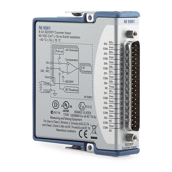
- Page 1 GETTING STARTED GUIDE NI 9361 8 Counter DI, 0 V to 5 V Differential/0 V to 24 V Single-Ended, 32 Bit, 102.4 kHz...
-
Page 2: Safety Guidelines
This document explains how to connect to the NI 9361. Before you begin, complete the software and Note hardware installation procedures in your chassis documentation. The guidelines in this document are specific to Note the NI 9361. The other components in the system might not meet the same safety ratings. -
Page 3: Safety Voltages
1,000 Vrms, verified by a 5 s dielectric withstand test Vsup inputs-to-earth ground (up to 3000 m) Continuous 60 VDC, Measurement Category I Withstand 1,000 Vrms, verified by a 5 s dielectric withstand test NI 9361 Getting Started Guide | © National Instruments | 3... - Page 4 This category is for measurements of voltages from specially protected secondary circuits. Such voltage measurements include signal levels, special equipment, limited-energy parts of equipment, circuits powered by regulated low-voltage sources, and electronics. 4 | ni.com | NI 9361 Getting Started Guide...
-
Page 5: Safety Guidelines For Hazardous Locations
CAT III, or CAT IV. Safety Guidelines for Hazardous Locations The NI 9361 is suitable for use in Class I, Division 2, Groups A, B, C, D, T4 hazardous locations; Class I, Zone 2, AEx nA IIC T4 and Ex nA IIC T4 hazardous locations; and nonhazardous locations only. -
Page 6: Special Conditions For Hazardous Locations Use In Europe And Internationally
Zone 2 hazardous locations, in ambient temperatures of -40 °C ≤ Ta ≤ 70 °C. If you are using the NI 9361 in Gas Group IIC hazardous locations, you must use the device in an NI chassis that has been evaluated as Ex nC IIC T4, Ex IIC T4, Ex nA IIC T4, or Ex nL IIC T4 equipment. -
Page 7: Electromagnetic Compatibility Guidelines
This product is intended for use in industrial locations. However, harmful interference may occur in some installations, when the product is connected to a peripheral device or test object, or if the NI 9361 Getting Started Guide | © National Instruments | 7... -
Page 8: Special Conditions For Marine Applications
Some products are Lloyd’s Register (LR) Type Approved for marine (shipboard) applications. To verify Lloyd’s Register certification for a product, visit ni.com/certification and search for the LR certificate, or look for the Lloyd’s Register mark on the product. 8 | ni.com | NI 9361 Getting Started Guide... -
Page 9: Preparing The Environment
EMC performance is attained. Preparing the Environment Ensure that the environment in which you are using the NI 9361 meets the following specifications. Operating temperature -40 °C to 70 °C... - Page 10 Refer to the device datasheet on ni.com/manuals Note for complete specifications. Connecting the NI 9361 The NI 9361 provides connections for eight digital input channels for the embedded counters. 10 | ni.com | NI 9361 Getting Started Guide...
- Page 11 Figure 1. NI 9361 Pinout DI3+ DI3- DI2+ DI2- DI6- DI6+ DI7+ DI7- DI0+ DI0- DI1+ DI1- DI5- DI5+ DI4+ DI4- NI 9361 Getting Started Guide | © National Instruments | 11...
- Page 12 Digital input signal connection for singled-ended measurements and positive digital input signal connection for differential measurements Negative digital input signal connection for differential measurements No connection Vout Voltage supply output connection Vsup Voltage supply input connection 12 | ni.com | NI 9361 Getting Started Guide...
-
Page 13: Connecting An External Power Supply
Connecting an External Power Supply You can optionally connect an external power supply to the NI 9361 to provide current for the devices that you connect to the module. Install a 2 A maximum, fast-acting fuse between the external power supply and the Vsup terminal. - Page 14 You can connect single-ended devices, such as TTL or CMOS to the NI 9361. For single-ended connections, connect the device out to the DI+ terminal on the NI 9361. Do not connect the DI- terminal on the NI 9361 for single-ended connections.
- Page 15 Single-Ended DI0+ Device DI0– NI 9361 Connecting Single-Ended Devices with Open Collector Outputs You can connect a device with open collector or open drain outputs to the NI 9361. NI 9361 Getting Started Guide | © National Instruments | 15...
- Page 16 NI 9361 An open collector device does not actively drive the signal high and relies on an external pull-up. The NI 9361 provides a 5 V pull-up on each DI+ pin that can be enabled individually to pull the signal high.
- Page 17 You can connect differential devices to the NI 9361. For differential connections, connect the positive device out to the DI+ terminal on the NI 9361 and the negative device out to the DI- terminal on the NI 9361. NI 9361 Getting Started Guide | © National Instruments | 17...
- Page 18 – DI0– NI 9361 The NI 9361 measures the difference between the DI+ and DI- terminals to determine if that difference is greater or less than the digital logic levels. If the difference between the terminals is within the input high range, the channel registers as high. If the...
-
Page 19: Incremental Encoders
Z causes the counter to be reloaded with a specific value in a specific phase of a cycle. Connecting Single-Ended Incremental Encoders You can connect single-ended incremental encoders to the NI 9361. NI 9361 Getting Started Guide | © National Instruments | 19... - Page 20 Figure 6. Connecting a Single-Ended Incremental Encoder Vsup External Power Supply – Vout DI0+ DI0– DI4+ Single-Ended Encoder DI4– Index DI7+ DI7– NI 9361 20 | ni.com | NI 9361 Getting Started Guide...
- Page 21 Connecting Differential Incremental Encoders You can connect differential incremental encoders to the NI 9361. NI 9361 Getting Started Guide | © National Instruments | 21...
- Page 22 Figure 7. Connecting a Differential Incremental Encoder Vsup External Power Supply – Vout DI0+ A– A– DI0– DI4+ Differential Encoder B– DI4– Index+ DI7+ Index– DI7– NI 9361 22 | ni.com | NI 9361 Getting Started Guide...
-
Page 23: Where To Go Next
NI 9361 Datasheet NI-RIO Help NI-DAQmx Help LabVIEW FPGA Help LabVIEW Help RELATED INFORMATION C Series Documentation Services & Resources ni.com/services ni.com/info cseriesdoc Located at ni.com/manuals Installs with the software NI 9361 Getting Started Guide | © National Instruments | 23... -
Page 24: Worldwide Support And Services
(EMC) and product safety. You can obtain the DoC for your product by visiting ni.com/certification. If your product supports calibration, you can obtain the calibration certificate for your product at ni.com/calibration. 24 | ni.com | NI 9361 Getting Started Guide... - Page 25 United States, visit the Worldwide Offices section of ni.com/niglobal to access the branch office websites, which provide up-to-date contact information, support phone numbers, email addresses, and current events. NI 9361 Getting Started Guide | © National Instruments | 25...
- Page 26 U.S. Government Customers: The data contained in this manual was developed at private expense and is subject to the applicable limited rights and restricted data rights as set forth in FAR 52.227-14, DFAR 252.227-7014, and DFAR 252.227-7015. © 2015—2016 National Instruments. All rights reserved. 376285B-01 Feb16...
Need help?
Do you have a question about the 9361 and is the answer not in the manual?
Questions and answers